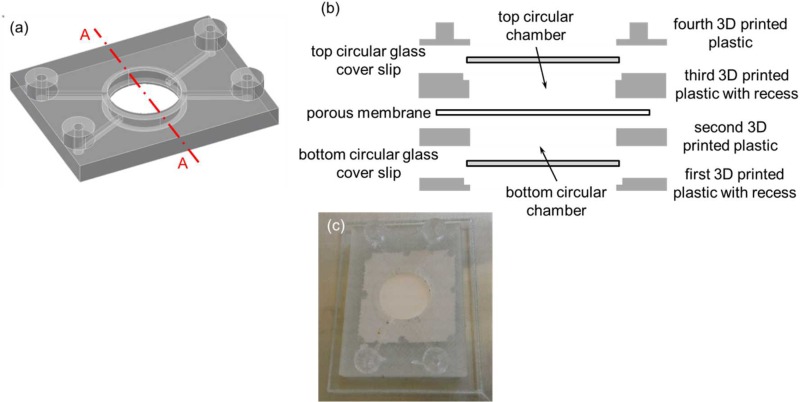
FIG. 5.
(a) 3D CAD model of the second perfusion fluidic device without the porous membrane, and the top and the bottom circular glass cover slips. (b) Schematic diagram of the exploded cross-sectional view of Section A–A depicted in (a) with the porous membrane separating the top and the bottom circular chambers. The top and the bottom circular glass cover slips were used as the top and the bottom surfaces of the top and the bottom circular chambers, respectively. (c) Second 3D printed perfusion fluidic device with the embedded 1.2 μm pore size cellular acetate membrane separating the top and the bottom circular chambers, and the integrated top and bottom circular glass cover slips. Channel cross-sectional dimensions were 1 mm × 1 mm and the two circular chambers were both 1 mm tall and 13 mm in diameter.

