

Abstract
Study Design
Cadaveric biomechanical analysis.
Objective
The aim of this study was to compare three interbody cage shapes and their position within the interbody space with regards to construct stability for transforaminal lumbar interbody fusion.
Methods
Twenty L2–L3 and L4–L5 lumbar motion segments from fresh cadavers were potted in polymethyl methacrylate and subjected to testing with a materials testing machine before and after unilateral facetectomy, diskectomy, and interbody cage insertion. The three cage types were kidney-shaped, articulated, and straight bullet-shaped. Each cage type was placed in a common anatomic area within the interbody space before testing: kidney, center; kidney, anterior; articulated, center; articulated, anterior; bullet, center; bullet, lateral. Load-deformation curves were generated for axial compression, flexion, extension, right bending, left bending, right torsion, and left torsion. Finally, load to failure was tested.
Results
For all applied loads, there was a statistically significant decrease in the slope of the load-displacement curves for instrumented specimens compared with the intact state (p < 0.05) with the exception of right axial torsion (p = 0.062). Among all instrumented groups, there was no statistically significant difference in stiffness for any of the loading conditions or load to failure.
Conclusions
Our results failed to show a clearly superior cage shape design or location within the interbody space for use in transforaminal lumbar interbody fusion.
Keywords: transforaminal lumbar interbody fusion, interbody cage, lumbar fusion, lumbar spine, spinal instrumentation, biomechanics
Introduction
Lumbar spinal arthrodesis is an increasingly common procedure with many variations on approach and technique.1 Transforaminal lumbar interbody fusion (TLIF) was introduced by Harms and Rolinger in 1982 and has become a popular method of lumbar spinal arthrodesis to treat a variety of disorders.2 TLIF has the potential advantages of less blood loss, shorter hospitalizations, less nerve root retraction, and less soft tissue disruption when compared with other techniques.3 4
The TLIF technique generally involves a posterior approach with partial resection of a unilateral facet joint and decompression of the foramina to gain access to the disk space with minimal thecal sac and nerve root retraction. Because the contralateral lamina, facet, and pars are spared, further surface area can be available for a posterior fusion, and potentially less spinal destabilization is imparted by the procedure.5 6 7 The TLIF has an additional benefit in that it can be performed at the upper lumbar levels where anterior access may be more problematic.8
The goals of placing the interbody fusion cages are to maintain or restore sagittal alignment and provide interbody stability as the fusion develops between motion segments. Many cage designs, sizes, and insertion techniques are commercially available today for implantation during a TLIF procedure. Despite the widespread use of these cages, little evidence is available to guide the surgeon on the optimal cage shape design and placement location within the interbody space. Cho et al compared kidney- and bullet-shaped cage designs and found no difference in construct stability in a cadaveric biomechanical study.9 Similarly, Faundez et al found no statistically significant difference in the construct stability between anteriorly or posteriorly placed interbody cages in a cadaveric biomechanical study.10 Clinically, however, higher rates of cage subsidence and nonunion were noted in patients undergoing TLIF with cages placed centrally versus cages placed anteriorly within the interbody space.11
We performed the present study to evaluate the effects of both the shape design and the position of the interbody cages on the construct stability. Our first hypothesis was that an interbody cage design with a larger contact area would confer greater stability than a smaller cage design. Our second hypothesis was that placement along the cortical rims either anteriorly or laterally between the end plates would confer greater stability than a cage placed centrally in the interbody space.
Methods
We acquired 13 fresh cadaveric human lumbar spines (age 73 ± 13 years, range: 51 to 88, 10 male, 3 female) from which 26 motion segments, L2–L3 and L4–L5, were harvested for biomechanical evaluation. Two L2–L3 and four L4–L5 specimens were excluded from testing due the presence of torn ligaments, disk calcification, or improper cement fixation prior to mechanical testing. Plain films of each motion segment were obtained to ensure no major structural abnormalities were present. Additionally, bone mineral density was obtained on each specimen via dual-energy X-ray absorptiometry scan to ensure no specimen was osteopenic.
The 20 motion segments were then randomized into three groups. Group I received a kidney-shaped TLIF cage (Verte-Stack Crescent, Medtronic, Minneapolis, Minnesota, United States). Group II received a novel articulating semilunar-shaped cage (AVID, Custom Spine, Parsippany, New Jersey, United States). Group III received a bullet-shaped cage design (Capstone, Medtronic; Fig. 1).
Fig. 1.
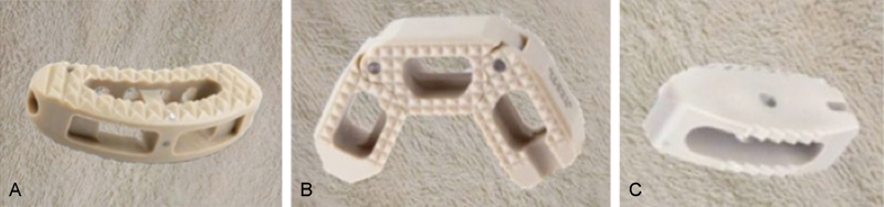
(A) Kidney-shaped interbody cage, group I; (B) articulating interbody cage, group II; (C) bullet-shaped interbody cage, group III.
Each group was then further divided into two subgroups so that each subgroup received a cage in a different anatomic location within the interbody space. Groups Ia and IIa received cages placed in the center of the disk space, and groups Ib and IIb received cages placed in the anterior portion of the disk space. Because the bullet-shaped cages were intended to be placed in an oblique fashion, group IIIa received cages placed in the center of the disk space, and group IIIb received cages placed in the lateral portion of the disk space. All groups had three specimens each with the exception of groups Ia and IIa, which received four specimens.
The surface areas of the kidney- and bullet-shaped cages were similar at 180 mm2 and 220 mm2, respectively. The articulated cage had a markedly larger surface area of nearly 500 mm2. To ensure uniformity, cages 10 mm in height were used in all groups.
Each motion segment was dissected free of soft tissue and potted up to its midbody in polymethyl methacrylate. Screws were inserted into the vertebral bodies prior to potting to ensure rigid fixation. Specimens were then mounted in a custom fixture and attached to a materials testing machine (ElectroPuls E10000, Instron Corporation, Norwood, Massachusetts, United States). The test system was fitted with a 10-KN, 100-Nm Dynacell biaxial load cell (Instron, Norwood, Massachusetts, United States). Following the methods of Murakami et al and Volkman et al, specimens were subjected to loading in pure compression and compression combined with a flexion moment, extension moment, right and left lateral bending moments, and right and left torsion.12 13
Prior to testing, the center of rotation (COR) of the motion segment was determined by applying a compressive point load (∼50 N) to different locations on the superior surface of the potted specimen until the position was identified that resulted in no observable angulation in the coronal and sagittal planes. The same COR was used for testing both the intact and the instrumented specimens. For subsequent testing, the loads were applied to the superior surface of specimen via a ball-and-socket joint (Fig. 2). The specimens were first subjected to preconditioning in pure compression from 350 to 650 N at 1 Hz for 1,000 cycles. Following preconditioning, the specimens were loaded in pure compression at a rate of 2.5 mm/min to 900 N. The maximum load of 900 N corresponds to physiologic compressive loading on the lumbar spine during daily activity.14
Fig. 2.
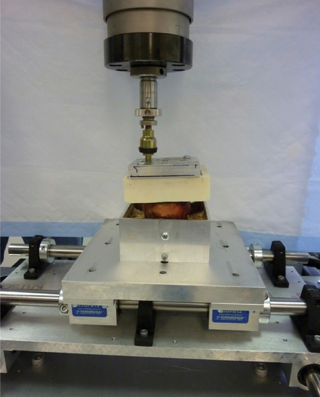
Experimental setup used for biomechanical evaluation. Specimen is pictured during right lateral bending testing.
The specimens were then loaded in combined compression and flexion by using the same loading protocol for pure compressive loading but with the loading point moved 20 mm anterior to the motion segment COR, producing a maximum flexion moment of 18 Nm at the instant of maximum compressive load. The peak moment of 18 Nm corresponds to the bending moment produced during daily bending and lifting tasks.15 Combined compression and bending tests were additionally performed in extension, right bending, and left bending by moving the loading point 20 mm posterior, to the right, and to the left of the COR, respectively. Finally, while under a constant compressive load of 900 N, specimens were rotated at 0.25 degrees/s to 10-Nm torque. The torsional tests were performed in both the left and right directions.
Three loading curves were obtained for each loading condition. For each trial, the stiffness in the linear range was determined by performing a curve fit between 450 and 900 N or 5 and 10 Nm for compression/bending and torsion tests, respectively. The compression/bending curves were adjusted for machine-load string compliance. Then torsional compliance was determined to be negligible. The average stiffness from the three trials was used in subsequent calculations.
For the instrumentation, a standard TLIF approach was performed with a partial unilateral facetectomy. For consistency, a right-sided facetectomy was performed on each specimen. An annulotomy was made sharply and a diskectomy was performed using the standard instruments including curettes and pituitaries. Care was taken to ensure that the end plates remained intact during the disk preparation. The appropriate TLIF cage was inserted to the proper position with the implant-specific instruments. Radiographs of each specimen were then obtained to confirm the position of each implant. Following instrumentation, the specimens were again subjected to preconditioning and the same loading protocol employed during testing in the intact state. To account for interspecimen variability, normalized stiffness, defined as the ratio of stiffness from instrumented testing to intact testing, was calculated for each specimen.
At the end of these experiments, an axial compressive load was applied at the COR until the motion segment failed in compression. The load to failure was recorded, as was the load at 5-mm displacement.
Wilcoxon signed rank tests were utilized for comparing the intact to instrumented specimen stiffness for each loading condition. Kruskal-Wallis tests along with Mann-Whitney tests adjusted with Bonferroni-Holm corrections were utilized to compare normalized stiffness among instrumented groups. Significance was set at p < 0.05.
Results
Combining the data from all test groups, intact specimens prior to instrumentation were significantly stiffer than instrumented specimens for all loading modes (p ≤ 0.005) with the exception of right axial torsion, which trended toward significance (p = 0.062; Table 1).
Table 1. Average intact and instrumented stiffness for various loading conditions.
| Applied load | Intact stiffness (mean ± SD) | Instrumented stiffness (mean ± SD) | Significance |
|---|---|---|---|
| Compression (N/mm) | 1,361 ± 394 | 1,011 ± 341 | <0.001 |
| Flexion (N/mm) | 839 ± 235 | 694 ± 237 | 0.003 |
| Extension (N/mm) | 802 ± 157 | 662 ± 148 | <0.001 |
| Right bending (N/mm) | 880 ± 258 | 708 ± 230 | <0.001 |
| Left bending (N/mm) | 882 ± 238 | 764 ± 229 | 0.005 |
| Right torsion (Nm/degree) | 6.5 ± 4.0 | 5.7 ± 2.8 | 0.062 |
| Left torsion(Nm/degree) | 6.0 ± 3.9 | 4.3 ± 2.1 | 0.001 |
Abbreviation: SD, standard deviation.
Note: Intact specimens demonstrated significantly greater stiffness than instrumented specimens for all loading conditions tested except right torsion.
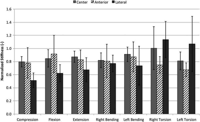
Among the instrumented specimens, there were no statistically significant differences in stiffness among the test groups for any of the loading conditions (Fig. 3). The lowest values of stiffness were displayed by the laterally placed bullet cage in compression, flexion, and extension. The highest values of stiffness were demonstrated by the centrally placed kidney cage and the laterally placed bullet cage in right torsion. The articulated cage was consistently stiffer when placed in the central position compared with the anterior position.
Fig. 3.
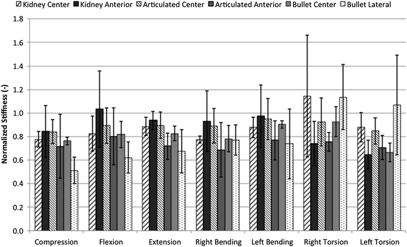
Instrumented stiffness normalized to intact specimen stiffness for various loading conditions. No significant difference in stiffness was demonstrated among all instrumented groups, regardless of cage design and placement. Results shown are mean ± standard deviation.
With data stratified by cage design only, making no distinction between cage positions, no significant differences in stiffness were observed for any of the loading conditions (Fig. 4). Moreover, with test data stratified by cage position only, making no distinction between cage designs, significantly greater stiffness was observed with the cages placed centrally versus laterally during pure compression (p = 0.015). No statistically significant differences were observed between cage positions for any other loading condition, although centrally and anteriorly placed cages tended to provide greater stiffness than laterally placed cages (Fig. 5).
Fig. 4.
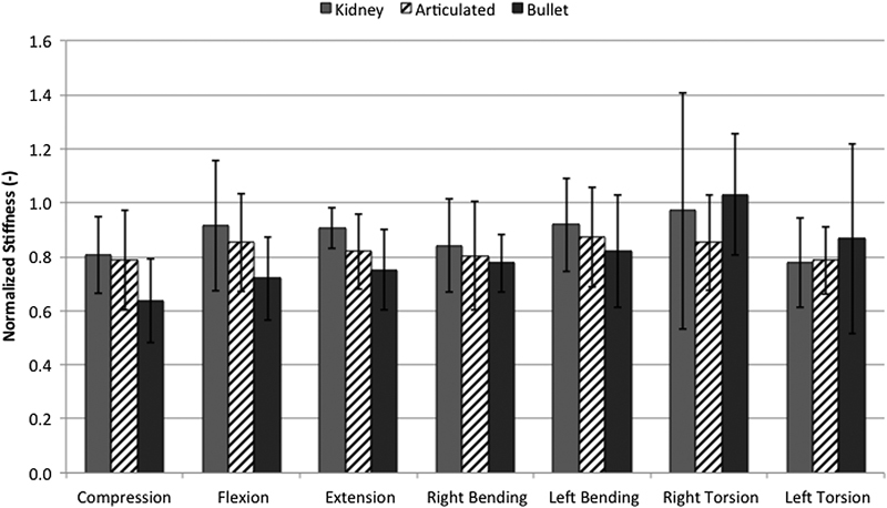
Normalized stiffness for various loading conditions with data grouped by cage design. No significant differences in stiffness were demonstrated between groups for all loading conditions. Results shown are mean ± standard deviation.
Fig. 5.
Normalized stiffness for various loading conditions with data grouped by cage position. Centrally placed cages demonstrated significantly greater stiffness in compression compared with laterally placed cages (p = 0.015). Results shown are mean ± standard deviation.
Load to failure testing revealed no difference among the instrumented groups (Fig. 6). The group with centrally placed bullet cages, which exhibited failure at 4.7-mm displacement, was the only group to fail before 5-mm displacement was reached. At the conclusion of testing when the interbody cages were retrieved, it was apparent that all failures occurred through end plate fracture. The anteriorly placed kidney cage had the highest failure load, and the articulated cage in the central position had the lowest failure load. At failure or 5-mm displacement, whichever occurred first, the centrally placed bullet cage displayed the highest load with the anterior kidney cage exhibiting the second highest load. The laterally placed bullet cage displayed the lowest load at 5-mm displacement.
Fig. 6.
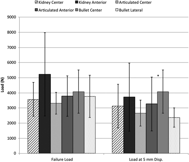
Compressive load to failure testing demonstrated no statistically significant differences between groups for failure load or load at 5-mm displacement (Disp.). *Failure load occurred before 5-mm displacement was reached. Results shown are mean ± standard deviation.
Discussion
We biomechanically tested three interbody cage designs utilized for TLIF in compression, flexion, extension, lateral bending, torsion, and compressive load to failure. A single cadaveric lumbar motion segment instrumented with cages alone was tested in a materials testing machine. For all load conditions tested, we found no difference in stiffness between the groups with different cage designs and positions within the interbody space. However, we did detect a significant decrease in stiffness from the intact motion segments to those that had undergone the TLIF procedure. When the data was stratified by cage position only, significantly greater stiffness was observed with the cages placed centrally versus laterally during pure compression, but no other significant findings were present for any other loading conditions. Of course, this model did not include any additional instrumentation, and the facetectomy and diskectomy understandably destabilized each motion segment. The greater effect on postinstrumentation torsion stiffness to the left than to the right may be explained by the right-sided facetectomy as well.
Our study is unique from others previously looking at optimizing TLIF constructs for several reasons. First, we did not utilize posterior instrumentation. Posterior instrumentation has been shown to increase construct stability, which in turn leads to a lower risk of pseudarthrosis.16 17 18 By not utilizing posterior instrumentation as done in similar studies, we eliminated it as a confounding factor and were able to assess the effect of the interbody cage design and position alone. Given the results of this study, the cage design and location are likely less important surgeon-controlled variables in determining the construct stability.
Second, we tested the hypothesis that a larger interbody surface contact area would lead to a more stable construct using one of the largest TLIF cages available (Custom Spine, AVID). This semi–lunar-shaped cage has two points of articulation, allowing twice the surface contact area of many other cage designs commercially available. Whereas we were unable to demonstrate the superiority of this device in this study, there is evidence to suggest that a larger interbody cage surface contact area enhances construct stability. Pimenta et al utilized a cadaveric model to compare construct stiffness among lumbar spine segments instrumented with two types of extreme lateral interbody fusion (XLIF) cages and one type of TLIF cage with and without pedicle screw fixation.19 The authors found that the larger XLIF cage provided greater construct stability than the smaller XLIF cage and the TLIF cage with and without posterior instrumentation. Additionally, in a finite-element analysis of the biomechanics of one versus two TLIF cages, Xu et al found greater stress on the cage, bone graft, and pedicle screws in the one-cage model.20 Although we did not observe a relationship of increasing surface contact area to construct stability in our study, perhaps a different cage geometry or a cage with an even larger surface area would have demonstrated this result. It is also possible that the larger cage size caused disruption of the end plate integrity not detected by plain radiography. Care must be taken during cage insertion to preserve the cortical bone.
Our study has several limitations, related primarily to the nature of in vivo biomechanical testing. As with similar studies, the stiffness of a given construct in the laboratory represents at best the in vitro stiffness at the initial time of instrumentation. In addition to initial construct stability, many other host factors lead to a successful fusion, such as bone density, tobacco use,21 22 advanced age,23 and diabetes mellitus.24 Moreover, there is the possibility that specimen variation may have factored into our results given that each specimen was instrumented by only one cage design. Selecting specimens without gross or radiographic structural abnormality and normal bone mineral density minimized this risk. The small sample size made it difficult to identify possibly clinically relevant differences between the test groups. Finally, due to the multistage design of this study, the specimens underwent multiple freeze–thaw cycles, which may have influenced motion segment material properties.
Conclusion
This study demonstrated no significant differences between three interbody cage designs nor interbody cage location in a TLIF model. Although many factors determine a successful fusion—some under the control and some not under the control of the surgeon—cage shape and location may be less important.
Acknowledgments
The authors thank Carol Schwalb for her assistance with radiographic imaging.
Footnotes
Disclosures Garet C. Comer, none Anthony Behn, none Shashank Ravi, none Ivan Cheng, Consulting: Nuvasive; Royalties: Nuvasive; Stock: Spine Innovation, Cytonics, SpinalCyte; Institutional grant: Cervical Spine Research Society
References
- 1.Pumberger M, Chiu Y L, Ma Y, Girardi F P, Mazumdar M, Memtsoudis S G. National in-hospital morbidity and mortality trends after lumbar fusion surgery between 1998 and 2008. J Bone Joint Surg Br. 2012;94(3):359–364. doi: 10.1302/0301-620X.94B3.27825. [DOI] [PubMed] [Google Scholar]
- 2.Harms J, Rolinger H. [A one-stager procedure in operative treatment of spondylolistheses: dorsal traction-reposition and anterior fusion (author's transl)] Z Orthop Ihre Grenzgeb. 1982;120(3):343–347. doi: 10.1055/s-2008-1051624. [DOI] [PubMed] [Google Scholar]
- 3.Hee H T, Castro F P Jr, Majd M E, Holt R T, Myers L. Anterior/posterior lumbar fusion versus transforaminal lumbar interbody fusion: analysis of complications and predictive factors. J Spinal Disord. 2001;14(6):533–540. doi: 10.1097/00002517-200112000-00013. [DOI] [PubMed] [Google Scholar]
- 4.Humphreys S C, Hodges S D, Patwardhan A G, Eck J C, Murphy R B, Covington L A. Comparison of posterior and transforaminal approaches to lumbar interbody fusion. Spine (Phila Pa 1976) 2001;26(5):567–571. doi: 10.1097/00007632-200103010-00023. [DOI] [PubMed] [Google Scholar]
- 5.Ames C P, Acosta F L Jr, Chi J. et al. Biomechanical comparison of posterior lumbar interbody fusion and transforaminal lumbar interbody fusion performed at 1 and 2 levels. Spine (Phila Pa 1976) 2005;30(19):E562–E566. doi: 10.1097/01.brs.0000180505.80347.b1. [DOI] [PubMed] [Google Scholar]
- 6.Holly L T, Schwender J D, Rouben D P, Foley K T. Minimally invasive transforaminal lumbar interbody fusion: indications, technique, and complications. Neurosurg Focus. 2006;20(3):E6. doi: 10.3171/foc.2006.20.3.7. [DOI] [PubMed] [Google Scholar]
- 7.Hallett A, Huntley J S, Gibson J N. Foraminal stenosis and single-level degenerative disc disease: a randomized controlled trial comparing decompression with decompression and instrumented fusion. Spine (Phila Pa 1976) 2007;32(13):1375–1380. doi: 10.1097/BRS.0b013e318064520f. [DOI] [PubMed] [Google Scholar]
- 8.Houten J K, Post N H, Dryer J W, Errico T J. Clinical and radiographically/neuroimaging documented outcome in transforaminal lumbar interbody fusion. Neurosurg Focus. 2006;20(3):E8. doi: 10.3171/foc.2006.20.3.9. [DOI] [PubMed] [Google Scholar]
- 9.Cho W, Wu C, Mehbod A A, Transfeldt E E. Comparison of cage designs for transforaminal lumbar interbody fusion: a biomechanical study. Clin Biomech (Bristol, Avon) 2008;23(8):979–985. doi: 10.1016/j.clinbiomech.2008.02.008. [DOI] [PubMed] [Google Scholar]
- 10.Faundez A A, Mehbod A A, Wu C, Wu W, Ploumis A, Transfeldt E E. Position of interbody spacer in transforaminal lumbar interbody fusion: effect on 3-dimensional stability and sagittal lumbar contour. J Spinal Disord Tech. 2008;21(3):175–180. doi: 10.1097/BSD.0b013e318074bb7d. [DOI] [PubMed] [Google Scholar]
- 11.Fukuta S, Miyamoto K, Hosoe H, Shimizu K. Kidney-type intervertebral spacers should be located anteriorly in cantilever transforaminal lumbar interbody fusion: analyses of risk factors for spacer subsidence for a minimum of 2 years. J Spinal Disord Tech. 2011;24(3):189–195. doi: 10.1097/BSD.0b013e3181e9f249. [DOI] [PubMed] [Google Scholar]
- 12.Murakami H, Horton W C, Tomita K, Hutton W C. A two-cage reconstruction versus a single mega-cage reconstruction for lumbar interbody fusion: an experimental comparison. Eur Spine J. 2004;13(5):432–440. doi: 10.1007/s00586-003-0668-y. [DOI] [PMC free article] [PubMed] [Google Scholar]
- 13.Volkman T, Horton W C, Hutton W C. Transfacet screws with lumbar interbody reconstruction: biomechanical study of motion segment stiffness. J Spinal Disord. 1996;9(5):425–432. [PubMed] [Google Scholar]
- 14.Nachemson A L. Disc pressure measurements. Spine (Phila Pa 1976) 1981;6(1):93–97. doi: 10.1097/00007632-198101000-00020. [DOI] [PubMed] [Google Scholar]
- 15.Adams M A, Dolan P. A technique for quantifying the bending moment acting on the lumbar spine in vivo. J Biomech. 1991;24(2):117–126. doi: 10.1016/0021-9290(91)90356-r. [DOI] [PubMed] [Google Scholar]
- 16.Oxland T R, Lund T. Biomechanics of stand-alone cages and cages in combination with posterior fixation: a literature review. Eur Spine J. 2000;9 01:S95–S101. doi: 10.1007/PL00010028. [DOI] [PMC free article] [PubMed] [Google Scholar]
- 17.McCarthy M J, Ng L, Vermeersch G, Chan D. A radiological comparison of anterior fusion rates in anterior lumbar interbody fusion. Global Spine J. 2012;2(4):195–206. doi: 10.1055/s-0032-1329892. [DOI] [PMC free article] [PubMed] [Google Scholar]
- 18.Vadapalli S, Robon M, Biyani A, Sairyo K, Khandha A, Goel V K. Effect of lumbar interbody cage geometry on construct stability: a cadaveric study. Spine (Phila Pa 1976) 2006;31(19):2189–2194. doi: 10.1097/01.brs.0000232720.23748.ce. [DOI] [PubMed] [Google Scholar]
- 19.Pimenta L, Turner A W, Dooley Z A, Parikh R D, Peterson M D. Biomechanics of lateral interbody spacers: going wider for going stiffer. ScientificWorldJournal. 2012;2012:381814. doi: 10.1100/2012/381814. [DOI] [PMC free article] [PubMed] [Google Scholar]
- 20.Xu H Ju W Xu N et al. Biomechanical comparison of transforaminal lumbar interbody fusion with 1 or 2 cages by finite-element analysis Neurosurgery 201373(2, Suppl Operative):ons198–ons205., discussion [DOI] [PubMed] [Google Scholar]
- 21.Zdeblick T A. A prospective, randomized study of lumbar fusion. Preliminary results. Spine (Phila Pa 1976) 1993;18(8):983–991. doi: 10.1097/00007632-199306150-00006. [DOI] [PubMed] [Google Scholar]
- 22.Hadley M N, Reddy S V. Smoking and the human vertebral column: a review of the impact of cigarette use on vertebral bone metabolism and spinal fusion. Neurosurgery. 1997;41(1):116–124. doi: 10.1097/00006123-199707000-00025. [DOI] [PubMed] [Google Scholar]
- 23.Kim Y J, Bridwell K H, Lenke L G, Rhim S, Cheh G. Pseudarthrosis in long adult spinal deformity instrumentation and fusion to the sacrum: prevalence and risk factor analysis of 144 cases. Spine (Phila Pa 1976) 2006;31(20):2329–2336. doi: 10.1097/01.brs.0000238968.82799.d9. [DOI] [PubMed] [Google Scholar]
- 24.Glassman S D, Alegre G, Carreon L, Dimar J R, Johnson J R. Perioperative complications of lumbar instrumentation and fusion in patients with diabetes mellitus. Spine J. 2003;3(6):496–501. doi: 10.1016/s1529-9430(03)00426-1. [DOI] [PubMed] [Google Scholar]