Abstract
A critical challenge for fluorescence imaging is the loss of high frequency components in the detection path. Such a loss can be related to the limited numerical aperture of the detection optics, aberrations of the lens, and tissue turbidity. In this paper, we report an imaging scheme that integrates multilayer sample modeling, ptychography-inspired recovery procedures, and lensless single-pixel detection to tackle this challenge. In the reported scheme, we directly placed a 3D sample on top of a single-pixel detector. We then used a known mask to generate speckle patterns in 3D and scanned this known mask to different positions for sample illumination. The sample was then modeled as multiple layers and the captured 1D fluorescence signals were used to recover multiple sample images along the z axis. The reported scheme may find applications in 3D fluorescence sectioning, time-resolved and spectrum-resolved imaging. It may also find applications in deep-tissue fluorescence imaging using the memory effect.
OCIS codes: (180.0180) Microscopy, (170.0110) Imaging systems, (100.3010) Image reconstruction techniques
1. Introduction
A critical challenge for fluorescence imaging is the loss of high frequency components in the detection path. Such a loss can be related to the limited numerical aperture of the detection optics, aberrations of the lens, and tissue turbidity. Here, we report an imaging scheme that integrates three innovations to tackle this challenge: 1) multilayer sample modeling [1, 2], 2) ptychography-inspired recovery procedures [3–6], and 3) lensless single-pixel detection [7]. In the reported scheme, we directly placed a 3D sample on top of a lensless single-pixel detector; no lens is used at the detection path. We then used a known mask to generate speckle patterns in 3D and scanned this known mask to different positions for sample illumination. The sample was modeled as multiple layers and the captured 1D fluorescence signal was used to recover multiple sample images along the z axis. Different from the previous lensless fluorescence imaging demonstrations [8, 9], the achievable resolution of the reported scheme is determined by the speckle size of the illumination patterns, where we encode the 3D sample information into 1D fluorescence measurements. We note that, the general idea of encoding sample information using non-uniform illumination patterns is not new [10–13]. It has been demonstrated, among others, in structured illumination microscopy for improving the resolution beyond the diffraction limit [13]. In the reported approach, however, we combine the pattern-illumination strategy with single-pixel detection scheme for multiplexed lensless fluorescence imaging. In particular, we propose a multilayer single-pixel imaging framework for recovering 3D sample information from 1D fluorescence signals. Different from compressive sensing scheme [7], the proposed framework is inspired and modified from the multiplexed ptychographic algorithms [2–5], where we switch between the spatial and Fourier domains in an iterative manner. In the spatial domain, we update the multilayer sample estimate using the illumination patterns from the known mask. In the Fourier domain, we update the central pixel of the Fourier spectrum using the measured single-pixel fluorescence signals. The proposed single-pixel updating process in the Fourier domain, to the best of our knowledge, is novel and compatible with existing ptychographic and phase retrieval algorithms. In the following, we will first explain the recovery procedures and demonstrate the simulation results. We will then report the single-pixel experimental results using a regular microscope platform and a lensless setup. Finally, we will discuss the future directions.
2. Multilayer single-pixel imaging scheme and simulation results
In the reported scheme, we directly place a 3D sample on top of a single-pixel detector. The forward imaging model can be described as follows:
| (1) |
where Objectlayer_m(x, y) represents the mth-layer object image in the x-y domain, Pmn(x, y) represents the nth illumination pattern for object layer m, and In represents the 1D measurement from the single-pixel detection (a photodiode). The summation in Eq. (1) represents the signal summation over the x-y-z domain (summation over ‘m’ is the same as the summation of multilayer images at the z direction). Therefore, the detected 1D signal in our scheme represents a mixture of the object at different layers. We note that, scattering only changes the signal distribution and the total intensity remains the same in Eq. (1). The goal of the recovery process is to recover the multilayer object images Objectlayer_m(x, y) from single-pixel measurements In. The recovery process starts with the initial guess of the object images Objectlayer_m(x, y). Second, we define Ipm and Itm:, . We note that, Ipm(x,y) is a function of x and y while Itm represents the total signal energy of the mth pattern-encoded layer of the object. Third, we update Itm using the measurement In: . Fourth, we update the Ipm(x,y) in the Fourier domain using the following equation:
| (2) |
where denotes 2D Fourier transform and denotes the discrete delta function. The key idea of Eq. (2) is to use the total signal energy at layer m to update the central pixel of the Fourier spectrum of Ipm(x,y). This updating step, to the best of our knowledge, is novel and can be combined with existing Fourier ptychographic algorithm [6, 14, 15] for single-pixel phase retrieval. Finally, we update the mth layer object image in the spatial domain, similar to the pattern-illuminated Fourier ptychographic algorithm [5]:
| (3) |
The updating process will be repeated for all n single-pixel measurements and the entire process is terminated until convergence, which can be measured by the difference between two successive recoveries. In a practical implementation, we can simply terminate it with a predefined loop number, typically 20-100.
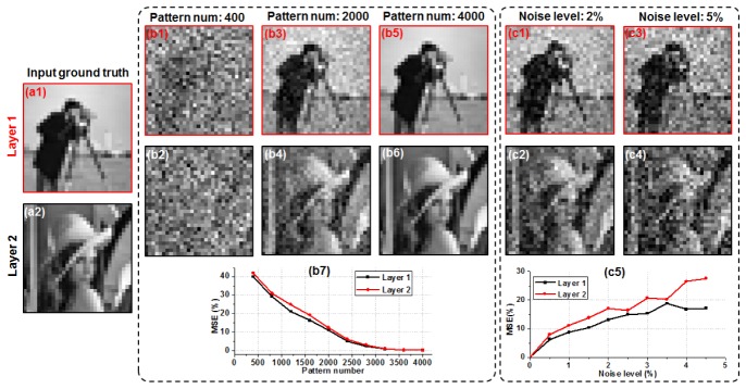
We will first validate the reported approach using simulations. In Fig. 1, we simulated a two-layer object (Fig. 1(a), 31 by 31 pixels) separated by 10 microns and illuminated by non-uniform patterns from a random mask (the illumination angle is 45 degrees). We then scanned the mask to different positions and simulated the 1D captured signals using Eq. (1). Based on the single-pixel recovery process discussed above, we can then recover the object images at different layers using the 1D signals. In Fig. 1(b), we show the recovery of the two layers using different number of illumination patterns. Figure 1(b7) quantifies the result using the mean square error (MSE). We can see that, the image quality increases when we use more patterns and saturates at ~3000 patterns. The total number of independent pixels for this two-layer object is ~2000, and thus, the oversampling factor is 3000/2000 = 1.5. Such a data redundancy may be necessary when we separate different object states from the 1D mixtures. Further investigation along this line is highly desired. In Fig. 1(c), we show the recovered images with different noise levels. Figure 1(c5) quantifies the noise performance using MSE, and as expected, the imaging performance gradually degrades as the noise increases.
Fig. 1.
Simulation of the multilayer single-pixel imaging scheme. (a) The input two-layer object. (b) The recovered results using different number of illumination patterns. (c) The recovered results with different levels of additive noises. MSE is used as a metric to quantify the results in (b7) and (c5).
In Fig. 2, we investigated the relationship between the number of layers in our model and the number of illumination patterns we need for the reconstruction. Figure 2(a) shows the imaging performance with respects to different numbers of illumination patterns and object layers. We need more illumination patterns when the number of object layers increases. Based on the MSE metric in Fig. 2(a), their relationship is linear. In other words, if we double the object layers in our model, we also need to double the number of illumination patterns for a successful reconstruction. In Fig. 2(b), we used a 3D confocal neuron cell data as the ground truth and simulated the single-pixel measurements using Eq. (1). We then modeled the cell with 10 layers and recover the images using the single-pixel measurements (Visualization 1 (256.8KB, MP4) ).
Fig. 2.
(Visualization 1 (256.8KB, MP4) ) Imaging performance of the multilayer imaging scheme with respect to different numbers of object layers and illumination patterns. MSE is used to quantify the imaging performance with 1 layer (a1), 2 layers (a2), and 10 layers (a3). (b) 10-layer single-pixel recovery of a 3D neuron cell (visualized using ImageJ 3D viewer).
We investigated the achievable resolution of the reported scheme in Fig. 3, where we used patterns with different speckle feature sizes (i.e., different illumination NAs) for sample illumination. Figure 3(a) shows the input resolution target. Figure 3(b) and 3(c) show illumination patterns with two different speckle sizes and their corresponding recoveries. We can see that, the achievable resolution of our imaging scheme is determined by the spatial-frequency support of the illumination pattern. In Fig. 3(d), we further quantify the imaging performance for the cases of two different speckle sizes. As expected, a higher resolution of the recovered image requires a larger number of illumination patterns.
Fig. 3.
Achievable resolution of the reported imaging scheme. (a) The input resolution target. (b) and (c): speckles with two different feature sizes and their corresponding recoveries. (d) MSE is used to quantify the imaging performance for the cases of two different speckle sizes.
3. Experimental validation
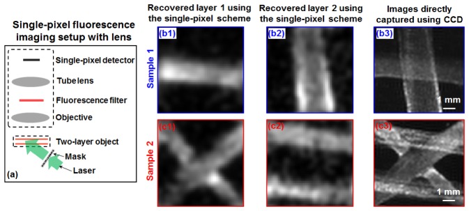
We have performed three experiments to validate the reported imaging scheme. In the first experiment, we used a microscope setup with a 1X objective lens and a single pixel detector (Si photodiode with 10 mm by 10 mm active sensing area) for image acquisition, as show in Fig. 4(a). In this experiment, we prepared two-layer fluorescence samples using orange fluorescence microspheres (size range: 1 - 5 µm; peak emission wavelength: 606 nm) deposited on two glass slides. The separation of these two layers is ~2 mm. We used a 40-mW 532 nm laser diode and a known chromium mask for generating speckle illumination. The incident angle is ~45 degrees in this experiment and the speckle feature size at the object plane is ~0.3 mm. We placed a fluorescence bandpass filter at the detection path (centered at 635 nm with 60-nm bandwidth). We scanned the mask to 1000 different spatial positions and captured the corresponding fluorescence signals using the single-pixel detector. The 1D signals were then used to recover the two-layer objects as shown in Fig. 4(b1)-(b2) and 4(c1)-(c2). As a comparison, we also replaced the single-pixel detector with a CCD and the captured images are shown in Fig. 4(b3) and 4(c3). We note that, the experiment in Fig. 4 directly points to a development for scanning confocal microscope, where single-pixel detector is used for image acquisition. We can, for example, remove the pinhole and model the single-pixel data as a signal mixture of multiple layers and recover the 3D images with one x-y scan.
Fig. 4.
Multilayer single-pixel imaging scheme using a lens setup. (a) The experimental setup. The fluorescence imaging results of sample 1 (b) and sample 2 (c).
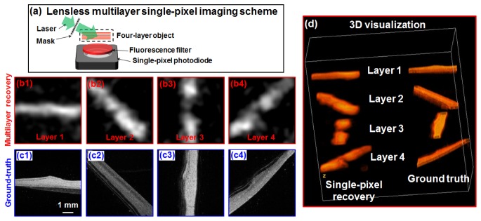
In the second experiment, we validate the reported imaging scheme using a lensless setup, as shown in Fig. 5(a). In this experiment, we prepared a 4-layer fluorescence objects using the same fluorescence microspheres. The separation of different layers is ~2 mm and we directly place this 4-layer object on top of the single-pixel detector. The incident angle of the speckle patterns is ~70 degrees. The distance between the first layer and the active sensing surface of the detector is ~5 mm and a fluorescence filter is placed in between. Figure 5(b) shows the recovered images of the 4 layers, and the ground-truth images are shown in Fig. 5(c). Figure 5(d) visualizes the results in 3D (Visualization 2 (1.8MB, MP4) ).
Fig. 5.
(Visualization 2 (1.8MB, MP4) ) Multilayer single-pixel imaging scheme using a lensless setup. (a) The experimental setup. We scanned the mask to 2000 different spatial positons and captured corresponding 1D fluorescence signal for recovery. The recovered images (b) and ground truth (c) of the 4 sample layers. (d) 3D visualization using ImageJ 3D Viewer.
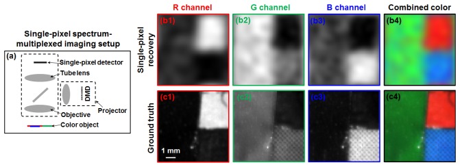
The reported scheme is not limited to the recovery of multiple layers of fluorescence samples. In the third experiment, we used it to recover sample images at multiple wavelengths. Figure 6 shows the results of recovering R/G/B channels of a color object. The experimental setup is similar to that of Fig. 4. In this experiment, we used a projector to generate 1500 known color speckle patterns for sample illumination, as shown in Fig. 6(a). The monochromatic 1D signals from the single-pixel detector were then used to recover the R/G/B channels in Fig. 6(b) and the ground truth images are shown in Fig. 6(c).
Fig. 6.
Spectrum-multiplexed single-pixel imaging scheme using a lens setup. (a) The experimental setup. (b) The recovered images of different color channels using the reported scheme. (c) The ground-truth images of the color object.
4. Summary and discussion
In summary, we have proposed and validated a single-pixel detection scheme for multilayer fluorescence imaging. The reported scheme integrates multilayer sample modeling, ptychography-inspired recovery procedures, and lensless single-pixel detection to tackle the challenge of fluorescence imaging from a new perspective. To the best of our knowledge, the single-pixel updating process (Eq. (2)) is new and can be combined with existing Fourier ptychographic algorithms [6, 14, 15] for the development of single-pixel Fourier ptychography; effort along this direction is ongoing.
There are several important implications of the reported scheme. 1) In a conventional laser scanning confocal microscope, we use a single pixel detector (photomultiplier tube) with a confocal pinhole for image acquisition. The confocal pinhole is for rejecting fluorescence signals that are not from the focal position. We can use the reported single-pixel recovery scheme for scanning confocal microscope. In this case, we can remove the confocal pinhole and model the captured single-pixel fluorescence signal as a mixture of signals from different sample layers. Based on a single x-y scan, we may be able to recover multiple layers of the sample. Effort along this direction is ongoing. 2) The reported scheme can be used for lensless single-pixel 3D fluorescence imaging. By using a high-speed photomultiplier tube, we can, for example, detect the fluorescence lifetime signal of the sample. 3) One challenge for deep tissue fluorescence imaging is tissue turbidity. We may be able to combine the reported scheme with memory effect [16] of the tissue to tackle this challenge. In this case, one can scan a speckle patterns by slightly changing the incident angles using high-speed Glavo mirrors. The fluorescence signals from the single-pixel detector can then be used to jointly recover the multilayer fluorescence samples and the speckle patterns [5, 17]. Finally, we provide the simulation code of reported scheme for the broad research community (please refer to the website listed under the email address).
Acknowledgment
This work was supported by NSF CBET 1510077 and CT Innovations.
References and links
- 1.Maiden A. M., Humphry M. J., Rodenburg J. M., “Ptychographic transmission microscopy in three dimensions using a multi-slice approach,” J. Opt. Soc. Am. A 29(8), 1606–1614 (2012). 10.1364/JOSAA.29.001606 [DOI] [PubMed] [Google Scholar]
- 2.Dong S., Guo K., Jiang S., Zheng G., “Recovering higher dimensional image data using multiplexed structured illumination,” Opt. Express 23(23), 30393–30398 (2015). 10.1364/OE.23.030393 [DOI] [PubMed] [Google Scholar]
- 3.Thibault P., Menzel A., “Reconstructing state mixtures from diffraction measurements,” Nature 494(7435), 68–71 (2013). 10.1038/nature11806 [DOI] [PubMed] [Google Scholar]
- 4.Batey D. J., Claus D., Rodenburg J. M., “Information multiplexing in ptychography,” Ultramicroscopy 138, 13–21 (2014). 10.1016/j.ultramic.2013.12.003 [DOI] [PubMed] [Google Scholar]
- 5.Dong S., Nanda P., Shiradkar R., Guo K., Zheng G., “High-resolution fluorescence imaging via pattern-illuminated Fourier ptychography,” Opt. Express 22(17), 20856–20870 (2014). 10.1364/OE.22.020856 [DOI] [PubMed] [Google Scholar]
- 6.Dong S., Shiradkar R., Nanda P., Zheng G., “Spectral multiplexing and coherent-state decomposition in Fourier ptychographic imaging,” Biomed. Opt. Express 5(6), 1757–1767 (2014). 10.1364/BOE.5.001757 [DOI] [PMC free article] [PubMed] [Google Scholar]
- 7.Duarte M. F., Davenport M. A., Takhar D., Laska J. N., Sun T., Kelly K. E., Baraniuk R. G., “Single-pixel imaging via compressive sampling,” IEEE Signal Process. Mag. 25(2), 83–91 (2008). 10.1109/MSP.2007.914730 [DOI] [Google Scholar]
- 8.Coskun A. F., Sencan I., Su T.-W., Ozcan A., “Lensless wide-field fluorescent imaging on a chip using compressive decoding of sparse objects,” Opt. Express 18(10), 10510–10523 (2010). 10.1364/OE.18.010510 [DOI] [PMC free article] [PubMed] [Google Scholar]
- 9.Coskun A. F., Su T.-W., Ozcan A., “Wide field-of-view lens-free fluorescent imaging on a chip,” Lab Chip 10(7), 824–827 (2010). 10.1039/b926561a [DOI] [PMC free article] [PubMed] [Google Scholar]
- 10.Pang S., Han C., Erath J., Rodriguez A., Yang C., “Wide field-of-view Talbot grid-based microscopy for multicolor fluorescence imaging,” Opt. Express 21(12), 14555–14565 (2013). 10.1364/OE.21.014555 [DOI] [PMC free article] [PubMed] [Google Scholar]
- 11.Arpali S. A., Arpali C., Coskun A. F., Chiang H.-H., Ozcan A., “High-throughput screening of large volumes of whole blood using structured illumination and fluorescent on-chip imaging,” Lab Chip 12(23), 4968–4971 (2012). 10.1039/c2lc40894e [DOI] [PMC free article] [PubMed] [Google Scholar]
- 12.Mudry E., Belkebir K., Girard J., Savatier J., Le Moal E., Nicoletti C., Allain M., Sentenac A., “Structured illumination microscopy using unknown speckle patterns,” Nat. Photonics 6(5), 312–315 (2012). 10.1038/nphoton.2012.83 [DOI] [Google Scholar]
- 13.Gustafsson M. G., “Surpassing the lateral resolution limit by a factor of two using structured illumination microscopy,” J. Microsc. 198(2), 82–87 (2000). 10.1046/j.1365-2818.2000.00710.x [DOI] [PubMed] [Google Scholar]
- 14.Zheng G., Horstmeyer R., Yang C., “Wide-field, high-resolution Fourier ptychographic microscopy,” Nat. Photonics 7(9), 739–745 (2013). 10.1038/nphoton.2013.187 [DOI] [PMC free article] [PubMed] [Google Scholar]
- 15.Guo K., Dong S., Zheng G., “Fourier Ptychography for Brightfield, Phase, Darkfield, Reflective, Multi-Slice, and Fluorescence Imaging,” IEEE J. Sel. Top. Quantum Electron. 22(4), 1–12 (2016). 10.1109/JSTQE.2015.2504514 [DOI] [Google Scholar]
- 16.Vellekoop I. M., Aegerter C. M., “Scattered light fluorescence microscopy: imaging through turbid layers,” Opt. Lett. 35(8), 1245–1247 (2010). 10.1364/OL.35.001245 [DOI] [PubMed] [Google Scholar]
- 17.Chakrova N., Heintzmann R., Rieger B., Stallinga S., “Studying different illumination patterns for resolution improvement in fluorescence microscopy,” Opt. Express 23(24), 31367–31383 (2015). 10.1364/OE.23.031367 [DOI] [PubMed] [Google Scholar]


