Abstract
Diffuse optical tomography (DOT) is an advanced imaging method used to visualize the internal state of biological tissues as 3D images. However, current continuous-wave DOT requires high-density probe arrays for measurement (less than 15-mm interval) to gather enough information for 3D image reconstruction, which makes the experiment time-consuming. In this paper, we propose a novel DOT measurement system using multi-directional light sources and multi-directional photodetectors instead of high-density probe arrays. We evaluated this system’s multi-directional DOT through computer simulation and a phantom experiment. From the results, we achieved DOT with less than 5-mm localization error up to a 15-mm depth with low-density probe arrays (30-mm interval), indicating that the multi-directional measurement approach allows DOT without requiring high-density measurement.
OCIS codes: (100.3010) Image reconstruction techniques, (110.0113) Imaging through turbid media, (170.3880) Medical and biological imaging
1. Introduction
Diffuse optical imaging is a method used to visualize the internal state of biological tissues using near-infrared (NIR) light. NIR light is more transmissive than surrounding bands in biological tissues and can be used to measure the oxygenation level of hemoglobin when applied with spectroscopic techniques (NIRS). Compared to large-scale imaging modalities such as X-ray computed tomography or magnetic resonance imaging (MRI), diffuse optical imaging has such advantages as the safety of NIR light, produced with a portable device at low cost, and few physical restrictions in measurement. These merits permit anyone, including babies, elderly people, and patients with an implanted electronic device, to be measured in a natural environment. Therefore, it is expected to be an easy-to-use tool for functional neuroimaging [1] and for breast cancer detection or monitoring [2,3].
However, due to high scattering of NIR light in biological tissue, it is still a difficult problem to accurately reconstruct internal images from diffused NIR light observation [4]. In typical diffuse optical measurement, multiple source probes and detector probes are placed on the tissue surface, and then the internal image is reconstructed from the observed light values using an image reconstruction algorithm. Previously, optical topography, which visualizes internal tissue as a 2D image along the surface, has been widely used [1,3,5] due to the difficulty of reconstruction along the depth direction. Recently, diffuse optical tomography (DOT) has received much attention as an advanced imaging method to visualize internal tissue as a 3D image. However, for three-dimensional imaging, it is necessary to obtain sufficiently richer measurement information to reconstruct internal tissues, and the development of a sophisticated image reconstruction algorithm is also required.
Thus far, DOT has been successfully applied to high-density measurement. In recent years, high-density CW (continuous-wave) DOT has been intensively studied in the functional neuroimaging field. A dense arrangement of source probes and detector probes on the scalp, with an inter-probe distance of around 10 mm, provides a number of multi-distance channels (source-detector pairs), which in turn construct overlapping optical paths inside the head. The combination of dense observation channels and an inversion algorithm permit three-dimensional visualization of cortical activity, even with a CW measurement. Using this high-density DOT, multiple research laboratories have visualized cortical hemodynamic changes in the visual area [6], somatosensory area [7], motor area [8–10], auditory area [11], and language area [11], among others, with a spatial resolution similar to that of functional MRI. However, the increasing number of measurement probes in high-density measurement brings about increased workload and complication of the experiment. In particular, in the experimental setup of functional neuroimaging, the hair at every probe position needs to be parted in order for the optodes to have good optical contact with the scalp, which is very time consuming [12]. In addition, every probe position needs to be measured by some means for accurate forward light propagation modeling for image reconstruction. Headaches have also been often reported in long-time NIRS measurement due to constriction by the measurement probes. These operations and problems would of course increase with an increased number of probes.
In this paper, we propose a new alternative to high-density measurement for increasing the amount of observation information obtained: using multi-directional sources and detectors. The light direction of emitting or receiving optodes has been a single direction in conventional diffuse optical measurements. Instead, the new measurement system uses multi-directional light emission and reception. Figure 1 depicts optical paths from a source probe to a detector probe. The NIR light path in biological tissue can be roughly described as “banana-shaped.” Here, if two beams are emitted from the same source probe as shown in Fig. 1(a) (s1: direction beneath, s2: oblique direction), two different light paths are obtained (shown in orange and yellow). Here, the direction beneath denotes the direction perpendicular to the surface without inclination. We propose not only the use of multi-directional sources but also that of multi-directional detectors in this paper. The multi-directional detector operates by receiving lights distinctively according to the incoming angle (Fig. 1(b)). The “multi-directionization” of both sources and detectors offers the following additional advantages. It provides a more homogeneous density of optical paths in the observation area because it generates a variety of optical paths around not only the source probes but also the detector probes. More strongly altered optical paths are obtained by assigning both emitting and receiving directions than by assigning either emitting or receiving direction alone.
Fig. 1.
Conceptual diagram of multi-directional measurement. (a) Optical paths with two different emitting angles. (b) Optical paths with two different detection angles.
To achieve multi-directional measurement, we developed a new optical measurement system. We employed a VCSEL array as light sources. VCSEL (vertical-cavity surface-emitting laser) is a type of laser diode that emits a beam perpendicular to the surface, as opposed to the parallel emission of conventional edge-type laser diodes. This feature enables us to form two-dimensional laser arrays with significantly increased density in a small space. The multi-directional source was developed by changing the direction of beams from the VCSEL array by a lens and a prism. In a similar way to the light source, we employed a photodiode array as a detector. The multi-directional detector was developed by changing the direction of incoming light by a lens and detecting it in a particular area of the photodiode array, depending on the incoming angle.
In order to evaluate the multi-directional DOT, we conducted two experiments. First, we conducted a simulation experiment to evaluate the performance of the multi-directional DOT under the condition of no unknown noise factor. Then, we conducted a phantom experiment to evaluate the multi-directional DOT using the new measurement system. We tested the multi-directional measurement with a rectangular probe arrangement having 30-mm intervals, which is most frequently used in conventional NIRS topography experiments [5]. In order to evaluate the performance of the multi-directional DOT, we generated a localized absorption change inside turbid media, performed DOT, and calculated the localization error of the estimates. In solving inverse problems, we used our previously proposed hierarchical Bayesian estimation algorithm, which achieves high localization accuracy by introducing a sparse-promoting prior and sensitivity-normalized regularization [13]. The mean localization error of the simulation experiment was 3.1 mm up to a 15-mm depth from the surface. The tomographic images of the phantom experiment were similar to those of the simulation experiment, and the mean localization error of the phantom experiment was 4.4 mm up to a 15-mm depth. These localization errors are considerably smaller than the probe interval of 30 mm. Consequently, the results demonstrate that “low-density DOT” becomes possible through the use of multi-directional optical measurement.
2. Methods
2.1 Multi-directional sources and detectors
In this section, we introduce a novel optical measurement system developed for multi-directional measurement. Then, we explain the expected optical paths inside tissue produced by the system’s multi-directional source and multi-directional detector.
2.1.1 Measurement system
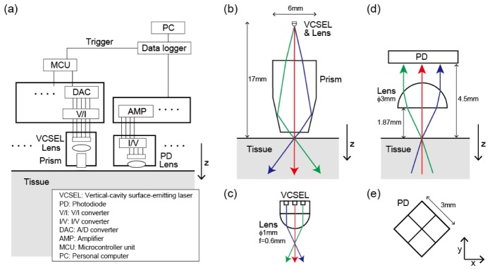
We developed a novel measurement system to achieve multi-directional optical measurement and used it in a phantom experiment. A schematic overview of the system is given in Fig. 2. The overall system consists of light source modules, photodetector modules and a controller (Fig. 2(a)). The light source module and the photodetector module are shown in detail in Figs. 2(b), 2(c) and Figs. 2(d), 2(e), respectively. The light source module consists of a VCSEL array, a lens, and a prism (Fig. 2(b)). The portion including the VCSEL array and the lens is enlarged in Fig. 2(c). The possible light paths are illustrated with different colors according to the directions. The multi-directional light emission of the source module is carried out as follows. A VCSEL array with dense light sources (200 μm intervals, product of RICOH [14]) is the source of multi-directional light. The light emitted by this VCSEL array is refracted by the lens depending on the position of the sources (Fig. 2(c)). Then, the angle of refraction is further amplified by the prism (Fig. 2(b)). The incident point on the tissue surface is designed to be the same in all light directions. The photodetector module consists of a photodetector and a hemispherical lens (Fig. 2(d)). Here, the photodetector is an array of four photodiodes (Fig. 2(e)). Incoming light through an aperture with a 2-mm diameter on the tissue surface is refracted by the hemispherical lens and, depending on the incoming angle, detected in some area of the photodiode array. Thus, the detector classifies incoming light from the tissue into four directions according to the incoming angle. Note that light coming from the direction below the array is not classified because all four photodiodes detect it.
Fig. 2.
Schematics of multi-directional optical measurement system. (a) Overview diagram. (b) Light-source module. (c) Enlarged figure of light-source module. (d) Detector module. (e) Arrangement of four photodiodes in xy-plane.
2.1.2 Optical paths by multi-directional sources and detectors
By using the multi-directional measurement system introduced in section 2.1.1, we can increase the number of observation channels without increasing the number of probes. In this section, we quantitatively evaluate the optical paths generated by multi-directional measurement by showing their sensitivity distributions calculated with a Monte Carlo photon migration simulator.
Let be the vector of absorption changes inside the discretized media and be the vector of logarithmic changes in photon fluence (from to ) measured by the observation channels. The following relationship is derived from the diffusion equation of continuous-wave measurement by using Rytov approximation [15–17]. Under the condition that the absorption changes are small, the measured changes in photon fluence are linearly related to the absorption changes as
| (1) |
where denotes measurement noise. The sensitivity matrix, the linear map from to , is given by
| (2) |
where represents the photon fluence of the light emitted from position with a unit intensity and measured at position . Photon fluence is linearly related to photon density in steady state. Equation (2) shows that the sensitivity is given by the normalized product of the photon fluence from light source to point , , and the photon fluence from point to detector , . In the area where the diffusion approximation is valid, the sensitivity distribution can be interpreted as the photon density distribution of an optical path from a light source to a detector because photons have no history information in the diffusion process. Thus, the sensitivity can be interpreted as the photon density distribution of an optical path as well as the input-output relation map. Therefore, we evaluate the optical paths of the multi-directional measurement by means of the sensitivity distribution. Note, however, that the above interpretation is not valid when the approximation is not valid, that is, when is large and in the place around a surface. Because is small and the region of interest is relatively deep in typical cases of DOT measurement, the optical paths can be evaluated using the sensitivity .
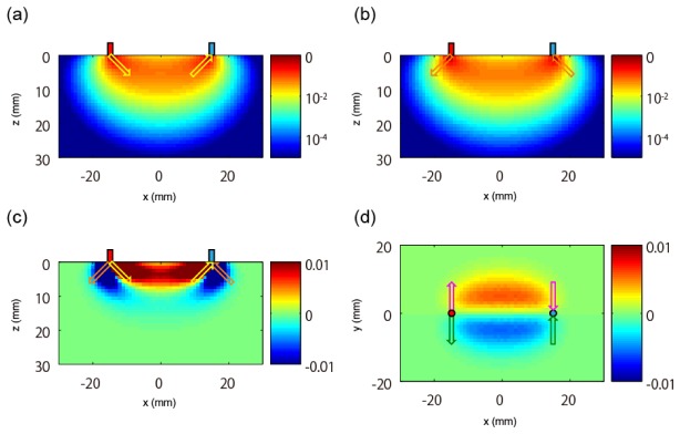
Figure 3 represents the sensitivity distributions obtained with various directions of light emission and detection. As will be described in detail in section 2.3.1, the optical parameters of the medium were set to be similar to those of human skin, and the sensitivity distributions were calculated with a Monte Carlo photon migration simulator. The voxel size is mm. Figure 3(a) represents the sensitivity distribution when both directions of light emission and detection are inclined inward, which means that the source emits light in a direction inclined by 45° toward + x directions from the direction beneath and the detector receives light from a direction inclined by 45° toward -x directions from the direction beneath (indicated by yellow arrows). In contrast, Fig. 3(b) represents a sensitivity distribution when both directions of light emission and detection are inclined outward (indicated by orange arrows). Although these two optical paths look similar, there are differences. In the case when light directions are not inclined, the peak voxels of sensitivity are located just beneath the source probe and the detector probe (data not shown). In the case when light directions are inclined inward, the peak voxels are moved 1 mm-voxel inward from the points beneath the source and the detector (Fig. 3(a)). In the case when light directions are inclined outward (Fig. 3(b)), although the peak voxels are on the points beneath, the outward/inward neighboring voxels have 90%/20% of the peak value, indicating that the distribution is biased outward. This result suggests that when the light direction changes, the sensitivity peaks move by about 1 mm, which roughly corresponds to the mean free path or the inverse of reduced scattering coefficient . Thus, the multi-directional source/detector produces an effect like setting multiple virtual sources/detectors around the probe position. Figure 3(c) represents the difference between the two sensitivity distributions shown in Figs. 3(a) and 3(b), indicating the difference in optical paths or observation information obtained by measurement channels with different light directions. The value of the sensitivity difference is on the order of 0.01, which corresponds to a sensitivity value at 14-mm or 15-mm depth from the surface. The sensitivity difference shown in Fig. 3(c) has different signs inside and outside of the “banana-shaped” optical path. Thus, these two areas can be discriminated by this sensitivity difference. However, novel information cannot be obtained in an excessively deep area because the sensitivity difference diminishes with depth. Other information can be obtained by changing light directions in the orthogonal direction. Figure 3(d) shows the distribution of difference between sensitivity when both directions of light emission and detection are inclined in the + y direction (indicated by magenta arrows) and in the -y direction (indicated by green arrows). Here, the xy-plane of the 10th deep voxel (9.5-mm depth) is shown. The sensitivity difference has different signs in the y>0 and y<0 regions. Therefore, these two areas can be discriminated by this sensitivity difference. Even though the optical paths of the multi-directional optical measurement are similar to each other, novel sensitivity distributions are obtained as differential distributions, and they can be used to discriminate several regions inside media.
Fig. 3.
Sensitivity distributions obtained with various directions of light emission and detection. Red and blue cylinders indicate a source probe and a detector probe, respectively. (a) Sensitivity distribution when the directions of both light emission and detection are inclined inward (indicated by yellow arrows). (b) Sensitivity distribution when both of these directions are inclined outward (indicated by orange arrows). (c) Distribution of difference between (a) and (b). (d) Distribution of difference between sensitivity when the two directions are inclined to + y direction (indicated by magenta arrows) and to -y direction (indicated by green arrows), respectively. The xy-plane of the 10th deep voxel (9.5-mm depth) is shown.
2.2 Experimental conditions
We conducted two experiments to evaluate diffuse optical tomography using multi-directional sources and detectors. First, we conducted a simulation experiment to evaluate the multi-directional DOT in such a condition that there is no unknown noise factor. Second, we conducted a phantom experiment to test the multi-directional DOT with the actual measurement system. In these experiments, we measured the localized absorption change with multi-directional sources and detectors placed on the media surface in a rectangular arrangement of 30-mm intervals. These two experiments were performed under nearly identical conditions so that we could compare the results.
2.2.1 Simulation conditions
The tissue was modeled to be a semi-infinite turbid medium whose optical parameters are similar to those of human skin: absorption coefficient , scattering coefficient , anisotropy , and refractive index [18].
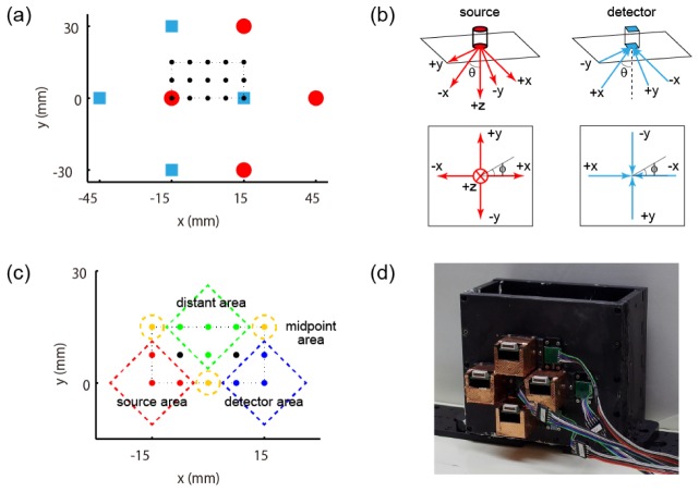
The sources and detectors were placed on the medium surface (z = 0) in a rectangular arrangement with 30-mm intervals (Fig. 4(a)). The red circles represent the sources, whose x,y,z positions were (45, 0, 0), (15, 30, 0), (−15, 0, 0), (15, −30, 0) [mm]. Each source emits 5-way multi-directional light (Fig. 4(b)), i.e. the direction beneath ( + z) and directions inclined by 45° toward + x, + y, -x, or -y directions from the direction beneath. These five directions were (θ, φ) = (0°, *), (45°, 0°), (45°, 90°), (45°, 180°), (45°, 270°) in the spherical coordinate, where θ indicates polar angle from the + z direction and φ indicates azimuth angle from the + x direction in the xy-plane. The blue squares represent the detectors, whose x,y,z positions were (15, 0, 0), (−15, 30, 0), (−45, 0, 0), (−15, −30, 0) [mm]. Each detector receives light from four directions discriminately (Fig. 4(b)), i.e. directions inclined by 45° toward + x, + y, -x, or -y directions from the direction beneath. These four directions were (θ, φ) = (45°, 0°), (45°, 90°), (45°, 180°), (45°, 270°) in the spherical coordinate.
Fig. 4.
Schematics of the experiment. (a) Arrangement of source probes and detector probes. Red circles represent the sources and blue squares the detectors. Black dots in the dotted line indicate locations where the absorber was placed. (b) Outgoing light directions from the source and incoming light directions to the detector. Perspective view and top view are shown. (c) Four areas categorized according to the positional relationship among the source, detector, and absorber. (d) Phantom water tank with the sources and the detectors attached. The detectors are covered with a copper ground for electromagnetic shielding.
The light intensity was measured with and without an absorber in the medium. We assumed that the absorber produces localized change of absorption coefficient that has 5-mm FWHM Gaussian distribution of peak value . The observed light intensities were simulated using the forward model, i.e. Eq. (1). In the measurement, Gaussian white noise of standard deviation 0.05 was added to the logarithm of the light intensities so that the noise level of the simulation experiment would be the same as that of the phantom experiment. The number of measurement samples was 200 each time, with and without the absorber.
The absorber was placed in one of the locations indicated by black dots in Fig. 4(a). These black dots indicating the center position of the absorber were located at intervals of 2.5 mm in a cuboid represented by the dotted line whose boundary is x = [-15,15], y = [0,15], z = [5,20] [mm]. The total number of absorber locations was 105. We repeated the observation five times in each position with different random seeds to reduce fluctuations in error evaluations, which means that we obtained five reconstructed images in each position and evaluated their errors. For analysis, we define four areas as shown in Fig. 4(c) to investigate the effect of positional relationship among the source, detector, and absorber on the estimation accuracy. We categorized the area near the source as “source area,” the area near the detector as “detector area,” the area near the midpoint of the source and detector as “midpoint area,” and the area distant from both the source and the detector as “distant area.”
2.2.2 Phantom experimental conditions
To demonstrate multi-directional DOT in a real situation, we conducted a liquid phantom experiment. The experimental apparatus is shown in Fig. 4(d). The tank was filled with a solution of 1% intralipid and ink to make the optical parameters of the liquid similar to those of human skin: absorption coefficient and reduced scattering coefficient . Note that these two parameters were the same as those in the simulation experiment.
The arrangement of the sources and detectors was the same as in the simulation experiment. The sources and detectors were located on the positions of red circles and blue squares, respectively (Fig. 4(a)). The wavelength and the power of the light source were 780 nm and 1 mW, respectively. The source emits 5-way multi-directional light and the detector receives light from four directions discriminatively in a similar fashion to the simulation experiment (Fig. 4(b)). However, in the phantom experiment, there were assembly errors in the positions and angles of the sources and integration effects of the incoming angles in the detectors. We describe these in detail in the first part of the results section of the phantom experiment (section 3.2.1).
The light intensities were measured with and without an absorber in the medium. This black spherical absorber had a 5-mm diameter made of acrylic resin. The absorber was accurately located with the use of a motorized stage. We measured the light intensity for 2 seconds at a 1000-Hz sampling rate each time, with and without the absorber. The standard deviation of the logarithm of observed light intensity was around 0.05.
The absorber was placed in one of the locations indicated by the black dots in Fig. 4(a). These black dots were located at intervals of 2.5 mm in a cuboid whose boundary is x = [-15,15], y = [0,15], z = [5,20] [mm]. Note, however, that we do not have data for z = 17.5 mm or data of y = 15 mm & z = 5, 10, 15, 20 mm in the phantom experiment. Therefore, the total number of absorber locations was 70. The observation was made only once in each absorber position.
2.3 Image reconstruction
The forward model construction and the inversion algorithm used for reconstructing a three-dimensional distribution of the absorption change are described below.
2.3.1 Forward problem
The forward problem in this study is described as a linear equation, as in Eq. (1) and Eq. (2). We calculated the photon fluence in Eq. (2) using Monte Carlo simulation software called MCX [19] with 109 photons. The optical parameters of the medium set for the Monte Carlo simulation were as follows: absorption coefficient , scattering coefficient , anisotropy , and refractive index . We used the same parameters for the analyses of both the simulation experiment and the phantom experiment. Although the calculation of the sensitivity matrix was performed with mm voxels in a sufficiently large area, we down-sampled them for image reconstruction with mm voxels and restricted our analysis to the area whose boundary is given by x = [-46.5, 46.5], y = [-31.5, 31.5], z = [0, 30] [mm] to reduce the amount of calculation.
When constructing the forward model, the geometry of the sources and detectors followed the experimental conditions as much as possible. Thus, the observed assembly errors of the sources and the integration effects of the detectors’ incoming angles were incorporated in the forward modeling for analysis of the phantom experiment.
2.3.2 Inverse problem
We used our previously proposed “Hierarchical Bayesian estimation algorithm” [13] for solving the inverse problem. According to the algorithm, first, a provisional solution was obtained by the sensitivity-normalized Tikhonov regularization, whose was determined based on the maximum value of the sensitivity for a region deeper than 19.5 mm (i.e. 7th deep voxel) as , (see [13] for details). Then, the solution was used as the initial value of an iteration algorithm used to refine the solution as . Here, is a localized smoothing filter to represent broadened solutions. We used a 5-mm FWHM Gaussian filter in this study. We set the confidence parameter to be zero, indicating the use of a non-informative prior. We repeated the iteration 3000 times. With this iteration number, the relative change in free energy (optimization criteria) was lower than 10−6. The number of voxels to be estimated was . The number of measurement data was 5dir (source) 4dir (detector) 9 pair = 180. Note that the measurement data were increased 20-fold ( = 5dir (source) 4dir (detector)) by using multi-directional measurement.
3. Results
Sections 3.1 and 3.2 summarize the results of the simulation experiment and the phantom experiment, respectively. The results of the simulation experiment show the performance of multi-directional DOT under the condition that there is no unknown noise factor. The results of the phantom experiment show more realistic performance, where there are various noise factors such as positional and angular errors of optodes, electrical noise, ambient light noise, and so on.
3.1 Simulation experiment
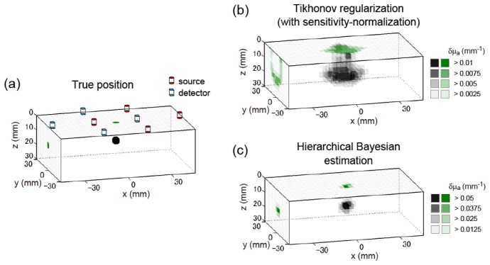
First, we visualize the results of a typical example in Fig. 5. Figure 5(a) shows the true absorber position. The position of the center of the absorber was (0, 0, 12.5) [mm]. The locations of multi-directional sources and detectors on the surface are superimposed on the image. Figure 5(b) shows the estimation results of the sensitivity-normalized Tikhonov regularization. The solution is overly smoothed because Tikhonov regularization cannot localize the solution. Figure 5(c) shows the estimation results of the hierarchical Bayesian estimation method, starting from the solution of the sensitivity-normalized Tikhonov regularization. This result demonstrates that the localization accuracy was improved by the hierarchical Bayesian method with a sparse-promoting prior. The center position of the estimated peak voxel was (0, 0, 13.5) [mm]. Thus, the positional error is 1.0 mm. This result shows that 3D reconstruction is possible in mm-order accuracy with a low-density (30-mm) arrangement of the multi-directional sources and detectors.
Fig. 5.
Example of 3D reconstruction image of the simulation experiment. The three-dimensional image (tomography) is represented in gray scale. The x-y maximum intensity projection and y-z maximum intensity projection are represented in green scale on the z = 0 surface and on the x = −46.5 cross section, respectively. (a) True distribution of the absorption change. Position of center of absorber is (0, 0, 12.5) [mm]. Red cylinders represent the sources, while blue square prisms represent the detectors. (b) Solution of sensitivity-normalized Tikhonov regularization. (c) Solution of hierarchical Bayesian estimation method.
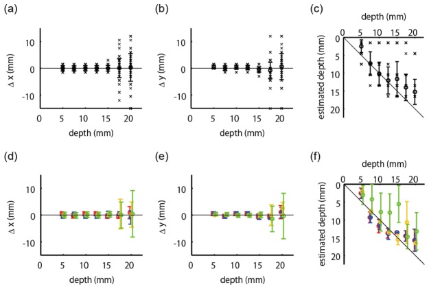
Next, we summarized the positional errors of the estimation results over all 105 absorber positions. Henceforth, we evaluated only the results obtained with our previously proposed hierarchical Bayesian estimation method. Due to light attenuation in turbid media, the deeper the absorption change is located, the more difficult the diffuse optical tomography is. Therefore, we evaluated errors at each depth of the absorption change. Figure 6(a) and Fig. 6(b) show positional errors in the x and y directions, respectively. Figure 6(c) shows the estimated depths as a function of the true depths. If the depth is accurately estimated, the value is on the diagonal line. The cross marks indicate individual estimation results. The error bar summarizes these results, whose circle and bar represent the mean and the standard deviation, respectively. The results of Fig. 6(a) and 6(b) indicate that the horizontal error is small up to a 15-mm depth, whereas it becomes suddenly large at depths greater than 17.5 mm. The estimated values in Fig. 6(c) are along the diagonal line, indicating that the depth can be estimated. However, some of the results were wrongly estimated in the shallowest place. The error bars in Fig. 6(c) are longer than those in Fig. 6(a) and 6(b), showing that the estimation of depth is more difficult than that of horizontal position.
Fig. 6.
Positional errors as functions of true depth of absorption change. The cross mark indicates individual results. The error bar represents meanSD. (a) Positional errors in x direction. (b) Positional errors in y direction. (c) Estimated depths. (d),(e),(f) Positional errors evaluated separately according to the four categories shown in Fig. 4(c). Red, blue, yellow, and green colors represent the data from the source area, detector area, midpoint area, and distant area, respectively. Conventions of Fig. 6(d), 6(e), and 6(f) are the same as in Fig. 6(a), 6(b), and 6(c), respectively, although cross marks are omitted.
The errors may depend on the positional relationship among the source, detector, and absorber, as well as the depth of the absorber. We evaluated the positional errors separately according to the four categories depicted in Fig. 4(c), as well as the depths, and summarized them in the second row of Fig. 6 with different colors. The red, blue, yellow, and green colors represent the data from the source area, detector area, midpoint area, and distant area, respectively. The conventions of Fig. 6(d), 6(e), and 6(f) are the same as those in Fig. 6(a), 6(b), and 6(c), respectively, although individual data points (cross marks) were omitted for visibility. The results of Fig. 6(d) and 6(e) show that the horizontal errors were not affected so much by the absorber position. In contrast, the results of Fig. 6(f) show that the depth errors of the distant area were distinctly larger than those in the other areas.
We also examined the amplitudes of estimated absorption changes. Figure 7 summarizes the peak values of estimated absorption change using boxplot as a function of depth of absorption change. The true peak value of absorption change in the simulation experiment was 0.1 mm−1. The results show that the amplitude was accurately estimated with a certain degree of precision when the absorption change was located in a shallow area. However, the deeper the absorption change was located, the more underestimated the amplitude was. The cause of this underestimation was the regularization introduced in the inversion algorithm, which suppresses the amplitude of the solution to avoid over-fitting. The regularization effect becomes dominant as the absorption change is located in a deeper area, since the observed light-intensity change weakens with depth relative to the regularization effect. The same phenomenon was also observed in our previous study [20].
Fig. 7.
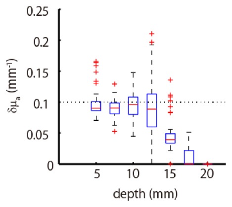
Estimated peak values of absorption change. The true peak value, indicated by the dotted line, was 0.1 mm−1. The boxplot summarizes each value at the depth where the absorption change was located.
The above results of the simulation experiment showed that multi-directional DOT was accurate up to a 15-mm depth. To quantitatively show its accuracy, we calculated the mean and standard deviation of the horizontal errors, depth errors, and total errors from all results up to a 15-mm depth and summarized them in Table 1. Here, the total error is Euclidean distance between the estimated peak position and the true peak position. The averaged positional error in the simulation experiment was 1.0 mm in horizontal, 2.7 mm in depth, and 3.1 mm in total, showing the high accuracy of multi-directional DOT. We also summarized the averaged errors separately according to the four categories depicted in Fig. 4(c). The results revealed that the depth error doubled when the absorption change was located in the distant area.
Table 1. Averaged positional error of simulation experiment up to a 15-mm depth.
| horizontal error | depth error | total error | |
|---|---|---|---|
| total area | 1.0 ± 0.9 mm | 2.7 ± 3.0 mm | 3.1 ± 2.9 mm |
| source area | 1.0 ± 0.7 mm | 1.9 ± 1.3 mm | 2.2 ± 1.3 mm |
| detector area | 1.0 ± 0.8 mm | 1.8 ± 1.3 mm | 2.2 ± 1.3 mm |
| midpoint area | 0.1 ± 0.5 mm | 1.2 ± 1.1 mm | 1.2 ± 1.2 mm |
| distant area | 1.1 ± 0.7 mm | 5.5 ± 4.0 mm | 5.7 ± 3.9 mm |
3.2 Phantom experiment
3.2.1 Assembly errors of measurement system
Since there were assembly errors in the light sources and integration effects in the detectors, we measured them before the phantom experiment. First, we measured source errors after assembling the experimental system. We found that there were variations in incident points on the medium surface depending on the individual sources and their light directions. The observed mean positional error of the incident points was 0.44 mm. We also measured outgoing light angles. The mean polar angle of the direction beneath was θ = 1.1°. The mean polar angle and its standard deviation of the other four directions were 38.1° and 1.4°, respectively. The mean error of azimuth angle was 1.3°. With respect to the detectors, there were few assembly errors because we attached them within 0.05-mm accuracy. However, there were uncertainties about how wide a range of incoming angle they received because they split the incoming light in such a way that the lens refracted light depending on its incoming direction, and the separated area detected them as shown in Fig. 2(e). We measured the amount of light received giving a parallel beam at various angles. We found that they received light from θ = 0° to θ = 30° and the weighted average of the incoming angle was θ = 13.4°. Moreover, they received light integrating the azimuth angle from −45° to 45° from the specified direction. These errors and integration effects were incorporated in the forward modeling for analysis of the phantom experiment.
3.2.2 Experimental results of phantom experiment
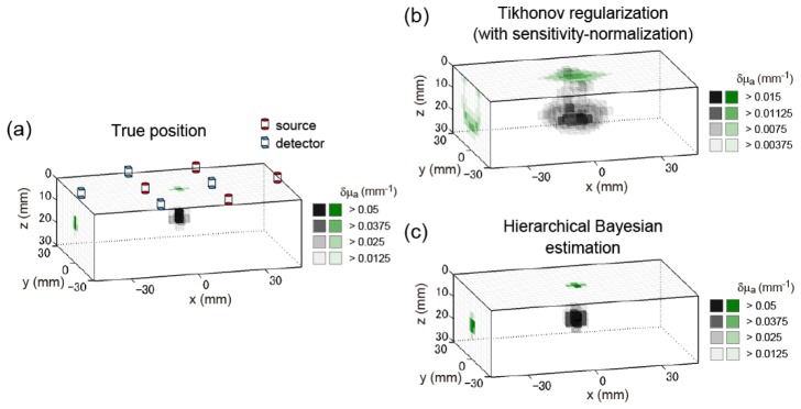
We first visualize the three-dimensional results of a typical example of the phantom experiment in Fig. 8. The conventions of Fig. 8 are the same as in Fig. 5. Figure 8(a) shows the true absorber position. The position of the center of the absorber was (0, 0, 12.5) [mm]. The locations of multi-directional sources and detectors on the surface are superimposed on the image. Figure 8(b) shows the estimation results of the sensitivity-normalized Tikhonov regularization. The distribution of the solution shown in Fig. 8(b) is similar to that shown in Fig. 5(b), implying that the multi-directional observation realized in the phantom experiment was similar to that of the simulation experiment. Figure 8(c) shows the estimation results of the hierarchical Bayesian estimation method, starting from the solution of the sensitivity-normalized Tikhonov regularization shown in Fig. 8(b). The center position of the estimated peak voxel was (0, −6, 13.5) [mm]. Thus, the positional error is 6.1 mm. This example showed that 3D reconstruction was also possible in the phantom experiment at mm-order accuracy, while the error was larger than that of the simulation experiment.
Fig. 8.
Example of 3D reconstruction image of phantom experiment. The three-dimensional image (tomography) is represented in gray scale. The x-y maximum intensity projection and y-z maximum intensity projection are represented in green scale on the z = 0 surface and on the x = −46.5 cross section, respectively. (a) True distribution of the absorption change. Position of absorber’s center is (0, 0, 12.5) [mm]. Red cylinders represent the sources, and blue square prisms represent the detectors. (b) Solution of sensitivity-normalized Tikhonov regularization. (c) Solution of hierarchical Bayesian estimation method.
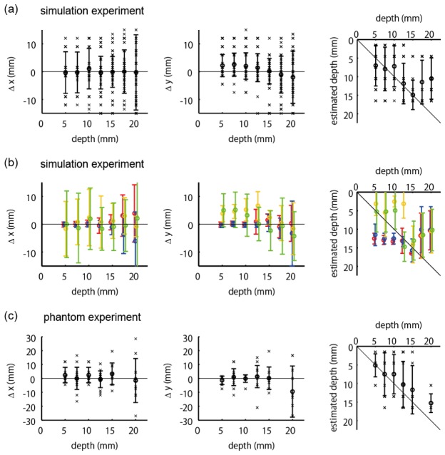
Next, we summarized the positional errors of estimation results over all 70 absorber positions. We evaluated the errors separately according to the depth of the absorption change, as with the previously described analyses of the simulation’s experimental results. Figure 9(a) and 9(b) show positional errors in x and y directions, respectively. Figure 9(c) shows the estimated depths as a function of the true depths. The cross marks indicate individual estimation results. The error bar summarizes these results, where the circle and bar represent the mean and the standard deviation, respectively. The results of Fig. 9(a) and 9(b) indicate that the horizontal error is relatively small up to a 15-mm depth, whereas it is large at a 20-mm depth. The depths can be estimated up to a 15-mm depth because the estimated values in Fig. 9(c) are along the diagonal line up to that depth.
Fig. 9.
Positional errors as functions of true depth of absorption change. The cross mark indicates an individual result. The error bar represents meanSD. (a) Positional errors in x direction. (b) Positional errors in y direction. (c) Estimated depths.
The analysis of the positional dependency (Figs. 6(d)-6(f)) of the phantom experiment is not described in the results section, since the measurement point in the phantom experiment is inhomogeneous and not sufficient for a detailed analysis. Instead, it is shown in the Appendix for reference.
We examined the amplitudes of estimated absorption changes. Figure 10 summarizes the peak values of estimated absorption change using a boxplot as a function of depth of absorption change. There is a tendency that the amplitude is more strongly underestimated in accordance with the depth of the absorption change, which is consistent with the simulation’s experimental results.
Fig. 10.
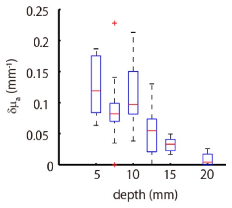
Boxplot of estimated peak values of absorption change as a function of depth at which the absorption change was located.
The above results indicate that the multi-directional DOT of the phantom experiment is valid up to a 15-mm depth, as is the case with the simulation experiment. To quantitatively show its accuracy, we calculated the mean and standard deviation of the horizontal errors, depth errors, and total errors from all results up to a 15-mm depth and summarized them in Table 2. Note that we removed one outlier, whose total error was larger than 30 mm, in this error evaluation. The averaged positional error in the phantom experiment was 2.6 mm in horizontal, 2.8 mm in depth, and 4.4 mm in total, showing that accurate multi-directional DOT can be achieved with the actual measurement system.
Table 2. Averaged positional error of phantom experiment up to a 15-mm depth.
| horizontal error | depth error | total error | |
|---|---|---|---|
| total area | 2.6 ± 2.6 mm | 2.8 ± 2.0 mm | 4.4 ± 2.4 mm |
3.3 Comparison with single-directional measurement
In this section, to compare multi-directional and conventional measurements, we examined the errors when the measurement was single-directional. We reconstructed the images from a subset of the acquired data. For the simulation experiment, we only used the data of direction beneath (θ = 0°) of both light emission and detection. For the phantom experiment, we used only the data of direction beneath of light emission and the summed value of the light intensities detected by the four photodiodes (Fig. 2(e)).
The summarized positional errors of the estimation results from the single-directional measurement are shown in Fig. 11. The efficacy of the multi-directional measurement over the single-directional measurement can be assessed by comparing Fig. 11(a), 11(b), and 11(c) with Fig. 6(a)-6(c), 6(d)-6(f), and Fig. 9, respectively. Figures 11(a) and 11(c) show that the estimation errors of the single-directional measurement of the simulation experiment and the phantom experiment are on the same order of magnitude and significantly larger than those of multi-directional measurement. Figure 11(b) provides more detailed information. In the single-directional measurement, if an absorption change occurs near a source or a detector probe, the horizontal position can be estimated because we can use four measurement data to determine the horizontal position. For example, if an absorption change occurs near a source probe, we can use the data from the four detector probes that neighbor the source probe. In contrast, the horizontal estimation was difficult in the midpoint and distant areas because fewer source-detector pairs detect it, and thus the measurement data are insufficient to identify the horizontal position. With respect to the depth, the single-directional measurement without overlapping channels would be insufficient to identify it. For example, we would not be able to distinguish between a weak change in shallow layers and a strong change in deep layers. In fact, the estimated depths were nearly flat shallower than 15 mm (Fig. 11(b)). Although there are abrupt changes in the estimated depths around 15-mm depth and therefore some apparent correlation between the true and estimated depth is seen, this is considered to be an artifact of the inversion algorithm related to the change of the signal-to-noise ratio accompanied by the change of the true depth of the absorption change.
Fig. 11.
Positional errors of single-directional measurement as functions of true depth of absorption change. (a) Positional errors of simulation experiment. Conventions are identical as in Figs. 6(a-c). (b) Positional errors of simulation experiment evaluated separately according to the four categories shown in Fig. 4(c). Conventions are identical as in Figs. 6(d-f). (c) Positional errors of phantom experiment. Conventions are identical as in Fig. 9.
To quantitatively evaluate the errors of the single-directional measurement, we again calculated the mean and the standard deviation of the errors from all results up to a 15-mm depth. For the simulation experiment, the horizontal, depth, and total errors were 5.5 ± 6.2 mm, 4.6 ± 3.0 mm, and 8.0 ± 5.9 mm, respectively (cf. Table 1). For the phantom experiment, the horizontal, depth, and total errors were 6.5 ± 6.4 mm, 4.6 ± 3.5 mm, and 8.8 ± 6.1 mm, respectively (cf. Table 2).
Figure 12 summarizes the peak values of estimated absorption change of the single-directional measurement. The estimated amplitudes vary more widely than the multi-directional measurement (cf. Figs. 7 and 10) and are more strongly affected by the true depth of the absorption change, suggesting that a weak change in shallow layers and a strong change in deep layers cannot be distinguished by single-directional measurements.
Fig. 12.
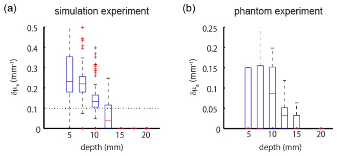
Boxplot of estimated peak values of absorption change as a function of depth at which the absorption change was located. Estimations were based on single-directional measurement of simulation experiment (a) and phantom experiment (b).
4. Discussion
We proposed and developed a novel multi-directional optical measurement system for diffuse optical tomography. Conventional DOT measurements have relied on optodes of a single light direction. Instead, the proposed measurement system uses multi-directional source probes and multi-directional detector probes. It increases the number of measurement data without increasing the number of probes by utilizing the multiple optical paths formed in multi-directional measurement. The results show that the sensitivity differences of various directions of light emission and detection are useful for discriminating regions inside media (Fig. 3). To test the efficacy of the multi-directional measurement system, we conducted two experiments: a simulation experiment and a phantom experiment. In these experiments, we performed DOT with a rectangular probe arrangement of 30-mm intervals (Fig. 4(a)). This arrangement is most frequently used in NIRS topography experiments. However, it cannot be used for conventional diffuse optical tomography because the probe density is insufficient for making overlapping optical paths. Nonetheless, the experimental results in this study show that accurate three-dimensional reconstruction is possible up to a 15-mm depth with 3.1-mm mean positional error in the simulation experiment and 4.4-mm mean positional error in the phantom experiment. These results demonstrate that multi-directional measurement makes DOT possible without requiring high-density measurement.
There are several reasons for larger estimation errors in the phantom experiment than those in the simulation experiment. One of the reasons may be that outgoing and incoming light angles of the phantom experiment were smaller than those of the simulation experiment, which were all 45°. The multi-directional source used in the phantom experiment was developed as follows. Light emitted by a VCSEL array is refracted by a lens. Then, the angle of refraction is further amplified by a prism. This two-step procedure achieved a mean outgoing angle of 38.1°. On the other hand, the multi-directional detector was developed by a single-step procedure. Incoming light is refracted by a lens and then received by an array of four photodiodes. The estimated mean incoming angle is 13.4°, which is much smaller than that of the simulation experiment. It is desirable for the angle to be large enough to make a variety of optical paths. An increased angle of multi-directional detectors is required in future work. Another reason for the inferior accuracy in the phantom experiment would be the assembly errors in positions and the angles of the light sources. In particular, there were considerable variations in incident points depending on the individual sources and light directions. The mean positional error was 0.44 mm. In contrast, the angular errors were around 1°, which is relatively small. Reducing the assembly errors is also required in future work. These assembly errors were incorporated in this study’s forward modeling process. We additionally evaluated the positional errors in the case where these errors were not incorporated in the forward modeling, which means that the same sensitivity as in the simulation experiment was used for estimation from the phantom experimental data. The mean positional error up to a 15-mm depth was 4.3 mm, which is not larger than that when errors were incorporated in the forward modeling. This result suggests that the estimate is not so sensitive to the positional and angular errors in the forward modeling of the multi-directional measurement.
The advantage of multi-directional measurement is the ability to accomplish DOT without requiring high-density measurement. This would accelerate the use of diffuse optical tomography in place of optical topography. Currently, high-density DOT offers attractive results but requires considerable experimental time and effort due to the increased number of measurement probes, which would have prevented the majority of researchers from using DOT. The proposed multi-directional measurement does not generate such a trade-off because it performs diffuse optical tomography with the same time and effort needed for conventional NIRS topography experiments. In addition, in the neuroimaging area, resting-state functional connectivity studies across cortical areas have recently attracted much attention [21]. These studies using high-density DOT require dozens or hundreds of measurement probes to cover a broad area of the cortex [11]. Multi-directional measurement would be especially effective in such cases to reduce experimental effort.
The major limitation of multi-directional DOT would be that the area where accurate estimation is possible is limited to a 15-mm depth from the surface. This is inferior compared to the high-density DOT. Our previous study showed that with a similar experimental condition and the same reconstruction algorithm, accurate estimation is possible up to 22.5 mm and 20 mm with high-density measurements of 13-mm and 18.4-mm intervals, respectively [13]. The cause of this limitation is that the difference of optical paths due to a different directional emission or detection diminishes in a deeper area (Fig. 3(c)). In the case of neuroimaging, this depth corresponds to a cortical surface. Thus, visualization by multi-directional DOT is limited to areas around the cortical surface. By contrast, because many distinct optical paths exist in a shallow area enough to reconstruct a three-dimensional image, it would be possible to utilize such a method that reconstructs a scalp’s hemodynamic change as well as a cortical hemodynamic change and remove the former [9,10,20]. The results also show that estimation was difficult in the distant area of the rectangular arrangement (Fig. 4(c)). The cause is weak sensitivity in the distant area because it is distant from any source or detector. This weak point may be overcome by using another probe arrangement, such as a hexagonal arrangement, or slightly raising the probe density.
Finally, although we showed the utility of multi-directional DOT by experiments using a low-density probe arrangement in this study, it would be interesting to evaluate how finely internal biological tissues are visualized by combining multi-directional measurement and high-density measurement in future work.
Acknowledgments
T.S., M.S., and O.Y. were supported by a contract with the National Institute of Information and Communications Technology entitled, 'Development of network dynamics modeling methods for human brain data simulation systems' (grant #173).
Appendix.
Positional dependency of estimation errors in the phantom experiment
The positional dependency of estimation errors (Fig. 6(d)-6(f)) in the phantom experiment is described here. Figure 13
Fig. 13.
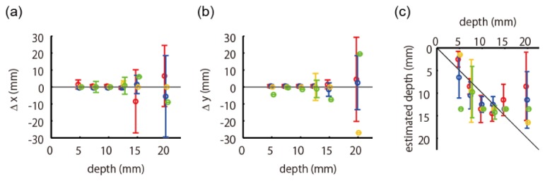
Positional errors as functions of true depth of absorption change. Conventions are the same as those in Fig. 6(d-f). The errors were evaluated separately according to the four categories shown in Fig. 4(c). The red, blue, yellow, and green colors represent the data from the source area, detector area, midpoint area, and distant area, respectively.
represents the positional errors evaluated separately according to the four categories depicted in Fig. 4(c) as well as the depths. The circle and bar in the error bar represent the mean and the standard deviation, respectively. The red, blue, yellow, and green colors represent the data from the source area, detector area, midpoint area, and distant area, respectively. We can see from Fig. 13 that the depth error of the distant area is notably larger than that of the other areas.
Table 3. Averaged positional error of phantom experiment up to a 15-mm depth.
| horizontal error | depth error | total error | |
|---|---|---|---|
| total area | 2.6 ± 2.6 mm | 2.8 ± 2.0 mm | 4.4 ± 2.4 mm |
| source area | 1.6 ± 1.6 mm | 2.1 ± 1.9 mm | 3.0 ± 1.9 mm |
| detector area | 1.9 ± 2.2 mm | 2.4 ± 1.7 mm | 3.7 ± 1.9 mm |
| midpoint area | 2.2 ± 3.5 mm | 3.3 ± 2.3 mm | 5.2 ± 2.3 mm |
| distant area | 4.4 ± 3.1 mm | 3.8 ± 2.6 mm | 6.5 ± 2.7 mm |
summarizes the mean and standard deviation of positional errors of the phantom experimental results up to a 15-mm depth. The values in the first row represent the averaged error values of all absorber positions up to a 15-mm depth (same as Table 2). The values in the second to fifth rows represent the averaged error values of each category depicted in Fig. 4(c). Note that we removed one outlier from the source area, whose total error was larger than 30 mm, in this error evaluation. We can see that the estimation error is large when the absorption change is located in the distant area, which is the same tendency observed in the simulation’s experimental results.
References and links
- 1.Ferrari M., Quaresima V., “A brief review on the history of human functional near-infrared spectroscopy (fNIRS) development and fields of application,” Neuroimage 63(2), 921–935 (2012). 10.1016/j.neuroimage.2012.03.049 [DOI] [PubMed] [Google Scholar]
- 2.Fang Q., Selb J., Carp S. A., Boverman G., Miller E. L., Brooks D. H., Moore R. H., Kopans D. B., Boas D. A., “Combined optical and X-ray tomosynthesis breast imaging,” Radiology 258(1), 89–97 (2011). 10.1148/radiol.10082176 [DOI] [PMC free article] [PubMed] [Google Scholar]
- 3.Roblyer D., Ueda S., Cerussi A., Tanamai W., Durkin A., Mehta R., Hsiang D., Butler J. A., McLaren C., Chen W. P., Tromberg B., “Optical imaging of breast cancer oxyhemoglobin flare correlates with neoadjuvant chemotherapy response one day after starting treatment,” Proc. Natl. Acad. Sci. U.S.A. 108(35), 14626–14631 (2011). 10.1073/pnas.1013103108 [DOI] [PMC free article] [PubMed] [Google Scholar]
- 4.Yamada Y., Okawa S., “Diffuse optical tomography: present status and its future,” Opt. Rev. 21(3), 185–205 (2014). 10.1007/s10043-014-0028-7 [DOI] [Google Scholar]
- 5.Maki A., Yamashita Y., Ito Y., Watanabe E., Mayanagi Y., Koizumi H., “Spatial and temporal analysis of human motor activity using noninvasive NIR topography,” Med. Phys. 22(12), 1997–2005 (1995). 10.1118/1.597496 [DOI] [PubMed] [Google Scholar]
- 6.Eggebrecht A. T., White B. R., Ferradal S. L., Chen C., Zhan Y., Snyder A. Z., Dehghani H., Culver J. P., “A quantitative spatial comparison of high-density diffuse optical tomography and fMRI cortical mapping,” Neuroimage 61(4), 1120–1128 (2012). 10.1016/j.neuroimage.2012.01.124 [DOI] [PMC free article] [PubMed] [Google Scholar]
- 7.Habermehl C., Holtze S., Steinbrink J., Koch S. P., Obrig H., Mehnert J., Schmitz C. H., “Somatosensory activation of two fingers can be discriminated with ultrahigh-density diffuse optical tomography,” Neuroimage 59(4), 3201–3211 (2012). 10.1016/j.neuroimage.2011.11.062 [DOI] [PMC free article] [PubMed] [Google Scholar]
- 8.Joseph D. K., Huppert T. J., Franceschini M. A., Boas D. A., “Diffuse optical tomography system to image brain activation with improved spatial resolution and validation with functional magnetic resonance imaging,” Appl. Opt. 45(31), 8142–8151 (2006). 10.1364/AO.45.008142 [DOI] [PubMed] [Google Scholar]
- 9.Yamashita O., Shimokawa T., Kosaka T., Amita T., Inoue Y., Sato M., “Hierarchical Bayesian model for diffuse optical tomography of the human brain: human experimental study,” JACIII 18(6), 1026–1033 (2014). 10.20965/jaciii.2014.p1026 [DOI] [Google Scholar]
- 10.Yamashita O., Shimokawa T., Aisu R., Amita T., Inoue Y., Sato M. A., “Multi-subject and multi-task experimental validation of the hierarchical Bayesian diffuse optical tomography algorithm,” Neuroimage 135, 287–299 (2016). 10.1016/j.neuroimage.2016.04.068 [DOI] [PubMed] [Google Scholar]
- 11.Eggebrecht A. T., Ferradal S. L., Robichaux-Viehoever A., Hassanpour M. S., Dehghani H., Snyder A. Z., Hershey T., Culver J. P., “Mapping distributed brain function and networks with diffuse optical tomography,” Nat. Photonics 8(6), 448–454 (2014). 10.1038/nphoton.2014.107 [DOI] [PMC free article] [PubMed] [Google Scholar]
- 12.Khan B., Wildey C., Francis R., Tian F., Delgado M. R., Liu H., Macfarlane D., Alexandrakis G., “Improving optical contact for functional near‑infrared brain spectroscopy and imaging with brush optodes,” Biomed. Opt. Express 3(5), 878–898 (2012). 10.1364/BOE.3.000878 [DOI] [PMC free article] [PubMed] [Google Scholar]
- 13.Shimokawa T., Kosaka T., Yamashita O., Hiroe N., Amita T., Inoue Y., Sato M. A., “Hierarchical Bayesian estimation improves depth accuracy and spatial resolution of diffuse optical tomography,” Opt. Express 20(18), 20427–20446 (2012). 10.1364/OE.20.020427 [DOI] [PubMed] [Google Scholar]
- 14.Harasaka K., Motomura H., Hara K., Ito A., Jikutani N., Sato S., “Low thermal resistance 780nm GaInPAs/GaInP 40ch VCSEL array for laser printers,” in 17th Microoptics Conference (IEEE, 2011). [Google Scholar]
- 15.Kak A. C., Slaney M., Principles of Computerized Tomographic Imaging (IEEE Press, New York, 1988). [Google Scholar]
- 16.M. A. O’Leary, “Imaging with diffuse photon density waves,” Ph.D. Thesis, University of Pennsylvania (1996). [Google Scholar]
- 17.Arridge S. R., “Optical tomography in medical imaging,” Inverse Probl. 15(2), R41–R93 (1999). 10.1088/0266-5611/15/2/022 [DOI] [Google Scholar]
- 18.Fang Q., “Mesh-based Monte Carlo method using fast ray-tracing in Plücker coordinates,” Biomed. Opt. Express 1(1), 165–175 (2010). 10.1364/BOE.1.000165 [DOI] [PMC free article] [PubMed] [Google Scholar]
- 19.Fang Q., Boas D. A., “Monte Carlo simulation of photon migration in 3D turbid media accelerated by graphics processing units,” Opt. Express 17(22), 20178–20190 (2009). 10.1364/OE.17.020178 [DOI] [PMC free article] [PubMed] [Google Scholar]
- 20.Shimokawa T., Kosaka T., Yamashita O., Hiroe N., Amita T., Inoue Y., Sato M. A., “Extended hierarchical Bayesian diffuse optical tomography for removing scalp artifact,” Biomed. Opt. Express 4(11), 2411–2432 (2013). 10.1364/BOE.4.002411 [DOI] [PMC free article] [PubMed] [Google Scholar]
- 21.Van Essen D. C., Smith S. M., Barch D. M., Behrens T. E. J., Yacoub E., Ugurbil K., WU-Minn HCP Consortium , “The WU-Minn human connectome project: an overview,” Neuroimage 80, 62–79 (2013). 10.1016/j.neuroimage.2013.05.041 [DOI] [PMC free article] [PubMed] [Google Scholar]


