Abstract
We demonstrate high-throughput label-free single-cell image cytometry and image-based classification of Euglena gracilis (a microalgal species) under different culture conditions. We perform it with our high-throughput optofluidic image cytometer composed of a time-stretch microscope with 780-nm resolution and 75-Hz line rate, and an inertial-focusing microfluidic device. By analyzing a large number of single-cell images from the image cytometer, we identify differences in morphological and intracellular phenotypes between E. gracilis cell groups and statistically classify them under various culture conditions including nitrogen deficiency for lipid induction. Our method holds promise for real-time evaluation of culture techniques for E. gracilis and possibly other microalgae in a non-invasive manner.
OCIS codes: (110.0180) Microscopy; (120.0120) Instrumentation, measurement, and metrology; (100.0100) Image processing
1. Introduction
Recent technological advances have enabled microalgae-based engineering of bioproducts [1,2]. Microalgae have a higher photosynthetic efficiency than plants and can be cultivated in agriculturally unused soils, which has helped us mass-produce microalgae such as Arthrospira, and Euglena. Biomass from mass-cultured microalgae has been exploited as a source of specific chemicals, such as β-carotene, astaxanthin, and polyunsaturated fatty acids for nutritional supplements, pharmaceutical drugs, cosmetic products, and biofuel [1]. Also, microalgae can alter their metabolism in response to changes in environmental conditions. Under stress conditions such as nutrient starvation, UV irradiation, and anaerobicity, many species of microalgae modify their biosynthetic pathways toward the formation and accumulation of metabolites such that they can endure these adverse conditions [2].
A particularly attractive species among such microalgae is Euglena gracilis, a unicellular microalgal species found in freshwater that has been used as a model organism for decades [3]. E. gracilis is neutrient-rich and known to accumulate paramylon (β-1,3-glucan in a crystalline form) as reserve polysaccharide in response to nitrogen deficiency or heterotrophic carbon sources. Furthermore, E. gracilis is also known to consume the intracellular paramylon in a hypoxic condition to obtain energy without oxygen. This process is accompanied by the production of wax ester which is suited for its conversion to biodiesel and aviation biofuel [4]. In order to fully explore these metabolic processes, it is important to monitor a large population of single E. gracilis cells in a short period of time, which has been difficult due to the lack of analytical methods that allow rapid, non-invasive, interference-free evaluation.
In this paper, we demonstrate high-throughput label-free single-cell image cytometry and image-based classification of live E. gracilis cells under different culture conditions. We conduct it with our high-throughput optofluidic image cytometer that builds on an optical time-stretch microscope [5–13] with a sub-micrometer resolution of 780 nm at an ultrahigh line rate of 75 Hz [14] combined with an inertial-focusing microfluidic device [15]. The image cytometer enables the acquisition of the images of single cells in a label-free manner without the need for fluorescent probes that can cause interference with cellular functions or bioproduct yield and is, therefore, suitable for monitoring the growth of E. gracilis cells and their response to environmental conditions. From our statistical image analysis, we identify cell-to-cell variations in morphological and intracellular phenotypes between E. gracilis cells under different culture conditions including nitrogen deficiency for lipid induction.
2. Experimental methods
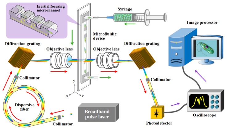
The optical time-stretch microscope is schematically shown in Fig. 1. The optical source is a Ti:Sapphire femtosecond pulse laser with a center wavelength, bandwidth, and pulse repetition rate of 780 nm, 40 nm, and 75 MHz, respectively. A pulse from the laser enters a single-mode dispersive fiber spool with a group-velocity dispersion of −240 ps/nm (Nufern 630-HP) in which the pulse is temporally stretched by the dispersion. The time-stretched pulse is spatially dispersed by the first diffraction grating with a groove density of 1200 lines/mm and focused on the microchannel in the microfluidic device via the first objective lens (Olympus) with a magnification of 40 × and a numerical aperture of 0.6. The transmitted pulse whose spectrum contains the spatial profile of the cell in the microchannel (just like spectrally encoded imaging [5,6,10,16,17]) is collected by the second objective lens with the same magnification and numerical aperture as the first objective lens and spatially recombined by the second diffraction grating identical in groove density to the first diffraction grating. Finally, the recombined pulse is detected by the high-speed photodetector (New Focus 1580-B) with a detection bandwidth of 12 GHz and digitized by the high-speed oscilloscope (Tektronix DPO 71604B) with a detection bandwidth of 16 GHz and a sampling rate of 50 GS/s. Pulses are repeated at the repetition rate of 75 MHz while E. gracilis cells are flowing in the microchannel. During this process, the 1D cross-sectional profile of a flowing E. gracilis cell in the lateral direction (orthogonal to the flow direction) is encoded into the spectrum (i.e., the temporal waveform) of each detected pulse, such that the 2D spatial profile of the E. gracilis cell can be obtained by digitally stacking the 1D cross-sectional profiles after the data is transmitted from the oscilloscope to the image processor through an Ethernet connection between them [7].
Fig. 1.

Schematic of the high-throughput optofluidic image cytometer.
For image cytometry of E. gracilis cells in a high-speed flow, the alignment of the cells in both the lateral and axial directions (orthogonal to the flow direction) is critical for accurate and precise acquisition of the images of the cells without out-of-focus blurring. For this purpose, we used a microfluidic device that can focus and order every single fast-flowing E. gracilis cell. Specifically, the microfluidic device employs geometry-induced inertial lift forces without the need for sheath fluid to control the alignment of E. gracilis cells [15]. The basic design of our microfluidic device is provided in [15]. The device was fabricated using standard soft lithography methods [18]. The dimensions of the microchannel are 80 μm (along the x axis), 56 μm (along the z axis), and 6 cm (along the y axis). The number of steps in the microfluidic device to induce inertial lift forces is 30 with a 1-mm interval. Each step has a height of 30 μm and a length of 10 μm. The device was connected with a PEEK tube (Upchurch Scientific) to a syringe (Thermo). A flow of E. gracilis cells was driven by a syringe pump (Harvard Apparatus) at a volume rate of 500 µl/min.
For our evaluation, we used E. gracilis NIES-48 provided by the Microbial Culture Collection at the National Institute for Environmental Studies (NIES, Japan). The cultures were grown in culture flasks with each working volume of 20 mL under 14:10 light:dark cycle illumination (130-150 μmol/m2/s) at 25°C. For all examinations, the stock culture of E. gracilis was grown in an autotrophic medium, AF-6 [19], as a pre-culture for at least 6 days. In the exponential growth phase, the cells in the AF-6 medium are under a nitrogen-sufficient condition (representing fresh E. gracilis cells), while in the stationary phase, the cells in the AF-6 medium are under a nitrogen-moderate condition (representing mature E. gracilis cells). On the other hand, the cells in the AF-6‒N medium (nitrogen nutrient omitted from AF-6) are under a nitrogen-deficient (‒N) condition after 5 days of cultivation (representing lipid-induced E. gracilis cells).
3. Experimental results and analysis
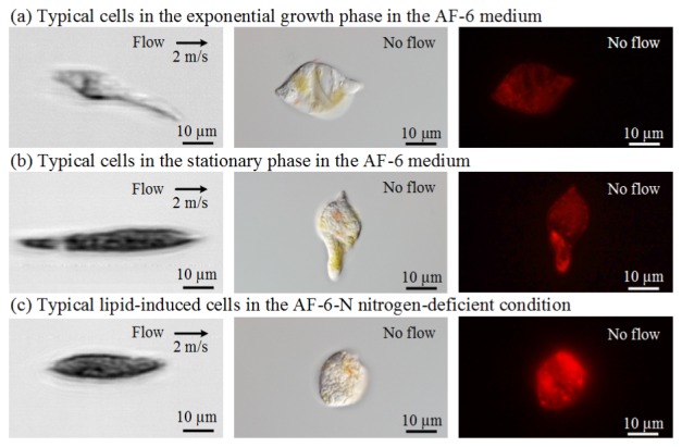
To show our system’s ability to acquire blur-free images of fast-flowing cells, we obtained images of these three types of E. gracilis cells with the image cytometer. Here the speed of the flowing cells in the microchannel is approximately 2 m/s. The throughput is calculated from the volume rate and cell concentration to be approximately 15,000 cells/s. In the 3 by 3 image matrix in Fig. 2, each row represents one culture condition as described in the last paragraph, while the images of each column are taken with different methods. The first column is taken by our image cytometer, the second column is taken by a CCD-based differential interference contrast microscope, and the third column is taken by a CCD-based fluorescence microscope (Leica DM2500 microscope equipped with Nomarski interference optics, N3 fluorescence filter cube, and an Olympus DP71 digital camera) with Nile Red lipid staining. A comparison between these images indicates that despite the fact that the flow speed is as high as 2 m/s, the image cytometer’s images are comparable in terms of morphological phenotypes to those of the conventional CCD-based microscope. The fluorescent images show the cells cultured under nitrogen deficiency contain more lipid than the other types.
Fig. 2.

Comparison of E. gracilis images taken by our image cytometer (left), CCD-based differential interference contrast microscope (middle), and CCD-based fluorescence microscope with Nile Red lipid staining (right).
Images of E. gracilis cells under the same culture and flow conditions are shown in Fig. 3. Each image consists of approximately 480,000 pixels (approximately 200 pixels in the lateral direction and approximately 2,400 pixels in the flow direction). This excessively large number of pixels in the flow direction indicates our system’s ability to acquire images of cells that flow at least 12 times faster without sacrificing the quality of the images, assuming that the microfluidic device can endure such a high normal pressure. Owing to the high quality of the images, the characteristics of these three types of cells can be extracted and compared for classification. Specifically, as shown in Fig. 3(a), the cells in the exponential growth phase in the AF-6 medium look more transparent. On the contrary, the cells in the stationary phase (Fig. 3(b)) and nitrogen-deficient condition (Fig. 3(c)) look opaque. The increased opacity is presumably caused by the intracellular accumulation of paramylon (β-1,3-glucan in a crystalline form) granules and lipid bodies under the nitrogen-deficient stress.
Fig. 3.
Images of E. gracilis cells under the three culture conditions taken by our image cytometer.
In order to differentiate and classify the differently cultured E. gracilis cells more accurately, we used the opacity distribution function (ODF) defined by
| (1) |
where O(j) is the opacity of the cell at pixel j (j = 1, 2, …, n) that ranges from 0 (completely transparent) to 1 (completely opaque) and n is the total number of pixels that cover the cell of interest. The average of the opacity values at all the pixels is then given by
| (2) |
The normalized standard deviation of the opacity values is given by
| (3) |
Based on these parameters, we analyzed the images of 1581 cells in total (N = 527 for each group) and generated a 3D scatter plot of the cell populations in terms of cell area, aveODF, and aveODF (Fig. 4(a)).
Fig. 4.
Analysis of the images of the E. gracilis cells under the three culture conditions (N = 527 per culture group).
Figure 4(a) shows the significant cell diversity of E. gracilis under different culture conditions. Here these cell populations are represented by three different colors (red, green, and violet). The properties of each cell (cell area, aveODF, and stdODF) in each population are indicated by a unique set of coordinates in the 3D space. To better visualize the differences between these populations, we obtained three 2D projections of the 3D scatter plot (Fig. 4(b)) and three sets of 1D histograms of the populations (Fig. 4(c)). The histogram of the cells in aveODF indicate that as the amount of nitrogen in the culture medium decreases due to their consumption of nitrogen, the overall cell distribution moves toward a higher aveODF value, which is expected since the amount of lipid is known to increase under nitrogen deficiency [4]. Furthermore, the histogram of the cells in stdODF shows that as the amount of nitrogen in the culture medium decreases, the diversity of the cells increases, meaning that the variations inside cells become larger. On the other hand, the histogram of the cells in cell area indicates that the overall cell area is small in the exponential growth phase in the AF-6 medium, becomes larger in the stationary phase in the AF-6 medium, and then decreases again under the nitrogen-deficient stress.
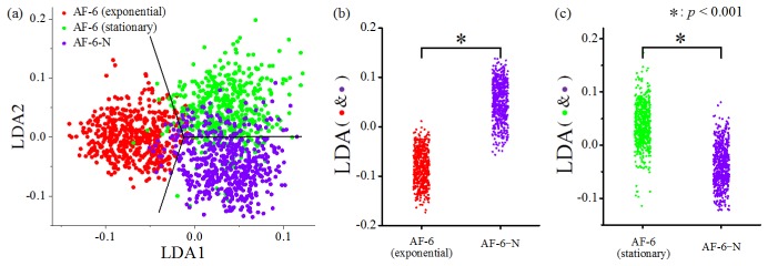
In addition to the qualitative discussion above, we also performed linear discriminant analysis (LDA) of the acquired data for validating whether our method can detect statistically significant differences between the populations under such large cell-to-cell variations. Figure 5(a) shows the 2D projection of the data points in the subspace spanned by the first two LDA axes, where the decision boundaries are also depicted to separate the data points into three groups of different culture conditions. Furthermore, in consideration of the application for biofuel production, LDA was also conducted between lipid-induced cells and two other cell groups as shown in Fig. 4(a) separately. By projecting the data points in Fig. 4(a) onto the corresponding LDA axes, we re-plotted the data points in Fig. 5(b) and Fig. 5(c). Figure 5(b) compares the lipid-induced cells and the cells in the exponential growth phase in the AF-6 medium while Fig. 5(c) compares the lipid-induced cells and the cells in the stationary phase in the AF-6 medium. Since the 1D histograms in Fig. 4(c) follow a Gaussian-like distribution, we used the Student’s t-test to determine the statistical differences between the data pairs in Fig. 5(b) and Fig. 5(c). In both of these two figures, the p-values are less than 0.001, which firmly indicates that our scheme is effective for evaluating the lipid production of E. gracilis cells by their appearance with high throughput in a label-free manner.
Fig. 5.
Results of the LDA analysis and Student’s t-test to show the statistical differences between lipid-induced cells and two other cell groups.
Acknowledgments
This work was funded mainly by the ImPACT Program of the CSTI (Cabinet Office, Government of Japan) and partly by Noguchi Shitagau Research Grant, New Technology Development Foundation, Konica Minolta Imaging Science Encouragement Award, JSPS KAKENHI Grant Numbers 25702024 and 25560190, JGC-S Scholarship Foundation, Mitsubishi Foundation, TOBIRA Award, and Takeda Science Foundation. C. L. and K. G. were partly supported by the International Postdoctoral Exchange Fellowship Program 2014 of the Office of the China Postdoctoral Council and Burroughs Wellcome Foundation, respectively. The fabrication of the microfluidic device was conducted at the Center for Nano Lithography & Analysis, University of Tokyo, supported by the MEXT, Japan.
References and links
- 1.Christenson L., Sims R., “Production and harvesting of microalgae for wastewater treatment, biofuels, and bioproducts,” Biotechnol. Adv. 29(6), 686–702 (2011). 10.1016/j.biotechadv.2011.05.015 [DOI] [PubMed] [Google Scholar]
- 2.Hessen D. O., De Lange H. J., Van Donk E., “UV-induced changes in phytoplankton cells and its effects on grazers,” Freshw. Biol. 38(3), 513–524 (1997). 10.1046/j.1365-2427.1997.00223.x [DOI] [Google Scholar]
- 3.Cramer M., Myers J., “Growth and photosynthetic characteristics of Euglena gracilis,” Arch. Mikrobiol. 17(4), 384–402 (1952). 10.1007/BF00410835 [DOI] [Google Scholar]
- 4.Georgianna D. R., Mayfield S. P., “Exploiting diversity and synthetic biology for the production of algal biofuels,” Nature 488(7411), 329–335 (2012). 10.1038/nature11479 [DOI] [PubMed] [Google Scholar]
- 5.Goda K., Tsia K. K., Jalali B., “Serial time-encoded amplified imaging for real-time observation of fast dynamic phenomena,” Nature 458(7242), 1145–1149 (2009). 10.1038/nature07980 [DOI] [PubMed] [Google Scholar]
- 6.Goda K., Jalali B., “Dispersive Fourier transformation for fast continuous single-shot measurements,” Nat. Photonics 7(2), 102–112 (2013). 10.1038/nphoton.2012.359 [DOI] [Google Scholar]
- 7.Lei C., Guo B., Cheng Z., Goda K., “Optical time-stretch imaging: Principles and applications,” Applied Physics Reviews 3(1), 011102 (2016). 10.1063/1.4941050 [DOI] [Google Scholar]
- 8.Chen C. L., Mahjoubfar A., Jalali B., “Optical data compression in time stretch imaging,” PLoS One 10(4), e0125106 (2015). 10.1371/journal.pone.0125106 [DOI] [PMC free article] [PubMed] [Google Scholar]
- 9.Xu J., Wei X., Yu L., Zhang C., Xu J., Wong K. K. Y., Tsia K. K., “High-performance multi-megahertz optical coherence tomography based on amplified optical time-stretch,” Biomed. Opt. Express 6(4), 1340–1350 (2015). 10.1364/BOE.6.001340 [DOI] [PMC free article] [PubMed] [Google Scholar]
- 10.Lau A. K., Shum H. C., Wong K. K., Tsia K. K., “Optofluidic time-stretch imaging - an emerging tool for high-throughput imaging flow cytometry,” Lab Chip 16(10), 1743–1756 (2016). 10.1039/C5LC01458A [DOI] [PubMed] [Google Scholar]
- 11.Chen H., Lei C., Xing F., Weng Z., Chen M., Yang S., Xie S., “Multiwavelength time-stretch imaging system,” Opt. Lett. 39(7), 2202–2205 (2014). 10.1364/OL.39.002202 [DOI] [PubMed] [Google Scholar]
- 12.Lei C., Chen H., Xing F., Chen M., Yang S., Xie S., “Time-stretch high-speed microscopic imaging system based on temporally and spectrally shaped amplified spontaneous emission,” Opt. Lett. 40(6), 946–949 (2015). 10.1364/OL.40.000946 [DOI] [PubMed] [Google Scholar]
- 13.Guo Q., Chen H., Weng Z., Chen M., Yang S., Xie S., “Fast time-lens-based line-scan single-pixel camera with multi-wavelength source,” Biomed. Opt. Express 6(9), 3610–3617 (2015). 10.1364/BOE.6.003610 [DOI] [PMC free article] [PubMed] [Google Scholar]
- 14.Ugawa M., Lei C., Nozawa T., Ideguchi T., Di Carlo D., Ota S., Ozeki Y., Goda K., “High-throughput optofluidic particle profiling with morphological and chemical specificity,” Opt. Lett. 40(20), 4803–4806 (2015). 10.1364/OL.40.004803 [DOI] [PubMed] [Google Scholar]
- 15.Chung A. J., Gossett D. R., Di Carlo D., “Three dimensional, sheathless, and high-throughput microparticle inertial focusing through geometry-induced secondary flows,” Small 9(5), 685–690 (2013). 10.1002/smll.201202413 [DOI] [PubMed] [Google Scholar]
- 16.Golan L., Yelin D., “Flow cytometry using spectrally encoded confocal microscopy,” Opt. Lett. 35(13), 2218–2220 (2010). 10.1364/OL.35.002218 [DOI] [PubMed] [Google Scholar]
- 17.Yelin D., Rizvi I., White W. M., Motz J. T., Hasan T., Bouma B. E., Tearney G. J., “Three-dimensional miniature endoscopy,” Nature 443(7113), 765 (2006). 10.1038/443765a [DOI] [PubMed] [Google Scholar]
- 18.Xia Y. N., Whitesides G. M., “Soft lithography,” Angew. Chem. Int. Ed. Engl. 37(5), 550–575 (1998). [DOI] [PubMed] [Google Scholar]
- 19.Andersen R. A., Berges J. A., Harrison P. J., Watanabe M. M., Recipes for Freshwater and Seawater Media in Algal Culturing Techniques (Academic Press, 2005), 429–538. [Google Scholar]


