Abstract
Filopodia are highly organized cellular membrane structures that facilitate intercellular communication. Near infrared photoimmunotherapy (NIR-PIT) is a newly developed cancer treatment that causes necrotic cell death. Three-dimensional low-coherent quantitative phase microscopy (3D LC-QPM) is based on a newly established low-coherent interference microscope designed to obtain serial topographic images of the cellular membrane. Herein, we report rapid involution of filopodia after NIR-PIT using 3D LC-QPM. For 3T3/HER2 cells, the number of filopodia decreased immediately after treatment with significant differences. Volume and relative height of 3T3/HER2 cells increased immediately after NIR light exposure, but significant differences were not observed. Thus, disappearance of filopodia, evaluated by 3D LC-QPM, is an early indicator of cell membrane damage after NIR-PIT.
OCIS codes: (110.6880) Three-dimensional image acquisition, (110.6915) Time imaging, (170.3880) Medical and biological imaging
1. Introduction
Near infrared photoimmunotherapy (NIR-PIT) is a new target-cell specific cancer treatment that employs an antibody-photoabsorber conjugate (APC) followed by NIR light exposure [1]. The first-in-human phase I trial of NIR-PIT in patients with inoperable head and neck cancer targeting epidermal growth factor receptor was approved by the US FDA in April 2015, and is currently underway (https://clinicaltrials.gov/ct2/show/NCT02422979). An APC consists of a cancer cell-specific monoclonal antibody (mAb) covalently conjugated to a photoabsorber, IRDye700DX (IR700), which is a silica-phthalocyanine derivative. The APC binds target molecules on the cell membrane. NIR light exposure at 690 nm induces nearly immediate cell necrosis characterized by severe damage to the cell membrane. This mechanism of cell death stands in contrast to traditional photodynamic therapy in which a lipid soluble porphyrin derivative enters the cell and causes damage to the mitochondria resulting in an apoptotic cell death [2–5]. Cells treated with NIR-PIT undergo rapid volume expansion leading to rupture of the cell membrane and extrusion of cell contents into the extracellular space. Thus, NIR-PIT induces nearly immediate necrotic cell death rather than apoptotic cell death which is induced by most other cancer therapies [6–8].
Filopodia are thin, actin-rich finger-like projections that extend from the cell edge. The role of filopodia in cell migration is well established in processes such as wound healing, angiogenesis, chemotaxis, embryonic development and adhesion [9–12]. As filopodia are widely used by migrating cells, it is not surprising that they are common in cancer cells where they cause invasive behavior within three-dimensional (3D) micro-environments [9–14]. Filopodia and filopodia-like protrusions have been reported to be critical not only for driving cancer cell metastasis, but also for promoting survival and proliferation of the disseminated carcinoma cells at a secondary organ [13,15]. Loss of filopodia on cancer cells after therapy could have implications for cancer cell function and could also serve as a pharmacodynamic marker of therapy.
Live cell imaging is becoming increasingly important to the understanding of cellular dynamics in many biological processes. One common strategy for conducting live cell imaging include the use of genetically introduced fluorescent proteins [16]. However, since it is difficult to genetically modify the cell membrane to introduce fluorescent proteins, the study of cellular membrane dynamics has been stymied. The situation is made even more difficult by the 3D nature of cell membranes which are difficult to study with planar imaging.
Three-dimensional dynamic low-coherent quantitative phase microscopy (3D LC-QPM) is a reflection-type interference microscope that uses a low-coherent light source to serially obtain topographic images of the cellular membrane at nanometer resolution in unmodified cells without labeling. This technique is based on interferometry between the sample light reflected from the cell surface and the reference one. 3D LC-QPM does not require cellular ‘label’ and can evaluate the full field surface topography of cultured cells and intrinsic membrane motion with a sensitivity of tens of nanometers [17,18]. Therefore, 3D LC-QPM could be a sensitive method to detect three-dimensional dynamic change in the cell membrane induced by NIR-PIT.
The purpose of this study was to investigate dynamic changes in the cellular membrane and particularly, the filopodia, by NIR-PIT using 3D LC-QPM.
2. Materials and methods
2.1 Reagents
Water soluble, silica-phtalocyanine derivative, IRDye700DX NHS ester was obtained from LI-COR Bioscience. Panitumumab, a fully humanized IgG2 mAb directed against epidermal growth factor receptor (EGFR), was purchased from Amgen (Thousand Oaks, CA, USA). Trastuzumab, 95% humanized IgG1 mAb directed against human EGFR type 2 (HER2), was purchased from Genetech (South San Francisco, CA, USA). All other chemicals were of reagent grade.
2.2 Synthesis of IR700-conjugated trastuzumab or panitumumab
Conjugation of dyes with mAb was performed according to previous reports [1,3,19]. In brief, panitumumab or trastuzumab (1mg, 6.8 nmol) was incubated with IR700 NHS ester (60.2 μg, 30.8 nmol) in 0.1 mol/L Na2HPO4 (pH 8.6) at room temperature for 1 hour. The mixture was purified with a Sephadex G25 column (PD-10; GE Healthcare, Piscataway, NJ, USA). The protein concentration was determined with Coomasie Plus protein assay kit (Thermo Fisher Scientific Inc., Rockford, IL, USA) by measuring the absorption at 595 nm with spectroscopy (8453 Value System; Agilent Technologies, Santa Clara, CA, USA). The concentration of IR700 was measured by absorption at 689 nm with spectroscopy to confirm the number of fluorophore molecules conjugated to each mAb. The synthesis was controlled so that an average of four IR700 molecules were bound to a single antibody. We abbreviate IR700 conjugated to trastuzumab as tra-IR700 and to panitumumab as pan-IR700.
2.3 Cell culture
3T3/HER2, SKOV3, and N87 cells expressing HER2, and MDA-MB-468 and A431 cells expressing human EGFR1 (HER1) were used in these experiments. 3T3/HER2 cells are generous gift from Dr. Ira Pastan in the Laboratory of Molecular Biology, NCI/NIH. SKOV3 and A431 cells are purchased from the ATCC (Rockville, MD, USA). N87 cells were purchased from ANTICANCER (San Diego, CA, USA). MDA-MB-468 cells were obtained from National Cancer Institute (NCI)-Frederick Cancer Division of Cancer Treatment and Diagnosis (DCTD) Tumor/Cell Line Repository (Frederick, MD, USA). Cells were grown in RPMI1640 supplemented with 10% FBS and 1% penicillin-streptomycin (Life Technologies, Gaithersburg, MD, USA) in tissue culture flasks in a humidified incubator at 37°C in an atmosphere of 95% air and 5% carbon dioxide.
2.4 Optical setup of 3D LC-QPM
The details of 3D LC-QPM setup were published by T. Yamauchi et al. [17,18]. Light emitted from a tungsten halogen lamp (center wavelength λc = 800 nm, see below) passed through a Michelson interferometer equipped with two identical water-dipping objective lenses (Nikon CFI Fluor 40XW; Water Immersion, NA = 0.80). The reflected wavefronts from the sample and the reference mirror were projected onto the CCD camera so that they form interference images. Based on the principle of low-coherence interference (also known as “white-light interference”), the interference images can only be observed when the optical-path-length from the beam splitter to the sample and the one to the reference mirror are precisely balanced. The vertical sectioning depth of the low-coherence interference, which is defined by the optical coherence length, is inversely proportional to the spectral bandwidth of the light source and was 0.93 μm in this setup, while the lateral resolution of the microscope calculated as the diffraction limit was 0.61 μm.
By means of low-coherence interference, a virtual “plane of section” (POS) was established where the horizontal cross section of the sample is obtained. The positions of the beam splitter, objective lenses, and reference mirror were fixed and only the sample was moved up and down across the POS by the piezoelectric transducer stage (PZT2), so that z-stack of horizontal cross sections was sequentially obtained. Just off the POS, interference fringes with a period corresponding to half of the wavelength of the light source were observed. The modulation amplitude of the oscillation, which is proportional to the reflectivity of the objects in the vicinity of the POS, was obtained by the 4-step quarter-lambda phase shifting method [17]. Although T. Yamauchi et al. has used 7-step phase shifting algorithm in their previous publication [17], we have adopted well-known 4-step algorithm. The reason is that we are mainly processing the intensity component of the interference, which is the envelope of the fringe, in this experiment and we have confirmed that in terms of intensity, the 7-step algorithm do not have much improvement compared to the 4-step one.
Details of the operation of optical filters are described below. The output light from the halogen lamp is spectrally filtered by an optical long-pass filter (LPF) and a dichroic mirror (DM). The DM, which reflects the light from 400 nm to 950 nm, is always in position, whereas the LPF which filters light shorter than 780 nm can be manually displaced from the optical path when the cells are exposed to NIR light for therapy. Because IR700 does not absorb light at wavelengths longer than 780 nm, the cells remain intact as long as the LPF is in front of the light source. The power of the NIR laser for path-length stabilization was measured 2 mW at the focal plane of the sample objective lens without culture medium. In the experiment, we put culture medium which absorbs the light and the actual irradiation of the NIR laser to the cells are smaller than 2 mW. Moreover, in order to minimize the potential damage of the cells by the NIR laser, we have put the laser light slightly off-centered so that the cells in the middle of the field-of-view are not irradiated by it.
2.5 Observation by 3D LC-QPM
Approximately two hundred thousand cells were seeded on a glass slide to which both an anti-reflection (AR) coating (bandwidth of 550-950 nm) and a reflection enhancement coating for 1.3 μm were applied [17,18] and incubated for 24 hours. Cells were separated into two groups, NIR-PIT and control. For NIR-PIT group 10 μg/mL of tra-IR700 or pan-IR700 were added to the culture medium and incubated for 6 hours. Control group cells were incubated without any APC. After incubation cells were washed once with phosphate-buffered saline and imaging was performed using 3D LC-QPM. The baseline data were obtained with a long-pass filter, which eliminates wavelengths less than 780 nm thus preventing NIR-PIT. The cell was exposed to NIR light (700-950 nm) for 25 sec, and then the observation was continued with the long-pass filter. Scanning parameters were as follows: the number of slices: 50-60 (depending on cell volume), slice thickness: 0.28 μm and acquisition time for each cycle: about 25 sec. All images were obtained in the axial plane. Total acquisition time was about 20 min.
2.6 Image analysis of 3D LC-QPM
2.6.1 Evaluation of filopodia
All LC-QPM imaging data was visualized using FluoRender software (http://www.sci.utah.edu/software/fluorender.html) [20]. Using these visualized images the presence or absence of filopodia was confirmed on each cell membrane. When long filopodia were confirmed, the number of filopodia at each cycle was calculated. When filopodia were too short for calculation, we visually evaluated the appearance of filopodia using a 3-point score where 2 = many filopodia are identified clearly, 1 = few or very short filopodia are identified, 0 = filopodia are not identified.
2.6.2 Morphological change of cancer cells after NIR light exposure
Morphological changes of cancer cells were evaluated when filopodia were present to determine the relationship between change in filopodia and morphological change in cancer cells after NIR-PIT. Image analysis was performed using Image J software (http://rsb.info.nih.gov/ij/). First, the cell was cropped from the original image because noise was seen in the background. Next, cell was segmented using a signal intensity (SI) threshold of 10 arbitrary units which was consistently over the noise floor. The volume and bottom area of contact of the cells with the dish were calculated. Finally, relative cell height was calculated using the equation: relative height of cell = volume / bottom area of cell.
2.7 Statistical analysis
Statistical analysis was performed with JMP 10 software (SAS Institute, Cary, NC). We determined the difference of each calculated parameter at 5, 10, and 15 min after NIR light exposure compared to the starting value using Steel’s multiple comparison for visual score of filopodia in MDA-MB-468 cells and Dunnett’s multiple comparison for other parameters. Differences of p < 0.05 were considered statistically significant.
3. Results
3.1 The presence or absence of filopodia
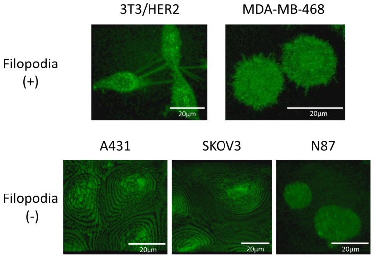
Filopodia-like structures were identified on 3T3/HER2 and MDA-MB-468 cells. Filopodia of 3T3/HER2 cells were long while those of MDA-MB-468 cells were short. Filopodia-like structures were not confirmed on cell membrane of A431, SKOV3, and N87 cells (Fig. 1).
Fig. 1.
Filopodia were detected on 3T3/HER2 and MDA-MB-468 cell. Filopodia of 3T3/HER2 cell were long while those of MDA-MB-468 cell were short. Filopodia were not detected on A431, SKOV3 and N87 cells.
3.2 Change of filopodia after NIR-PIT
3.2.1 3T3/HER2 cells
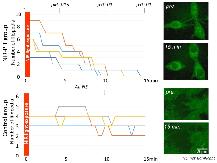
In the NIR-PIT group the number of filopodia decreased after NIR light exposure with a significant difference at all time points (p = 0.015 at 5 min, <0.01 at both 10 and 15 min after NIR-light exposure) (Fig. 2 and Visualization 1 (740.9KB, AVI) ). On the other hand, in the control group the number of filopodia was almost identical before and after light exposure yielding no significant difference (p = 0.98, 0.25 and 0.25 at 5, 10, and 15 min after NIR-light exposure, respectively) (Fig. 2 and Visualization 2 (1.5MB, AVI) ).
Fig. 2.
Change in number of filopodia on 3T3/HER2 cells after NIR light exposure. In the NIR-PIT group the number of filopodia decreased after NIR light exposure reaching significance at all time points (p = 0.015 at 5 min, <0.01 at 10 and 15 min after NIR-light exposure) (see Visualization 1 (740.9KB, AVI) ). On the other hand, in the control group the number of filopodia was unchanged (see Visualization 2 (1.5MB, AVI) ).
3.2.2 MDA-MB-468 cells
In the NIR-PIT group the visual score of filopodia decreased after NIR light exposure with significant differences at all time point (p = 0.01 at 5, 10 and 15 min after NIR-light exposure) (Fig. 3 and Visualization 3 (1.2MB, AVI) ). On the other hand, in the control group the visual score of the filopodia was practically identical and there was no significant difference (p = 1.00, 0.99 and 1.00 at 5, 10, and 15 min after NIR-light exposure, respectively) (Fig. 3 and Visualization 4 (1,021.7KB, AVI) ).
Fig. 3.
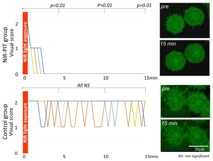
Change in visual score of filopodia on MDA-MB-468 cells after NIR light exposure. In the NIR-PIT group the visual score of filopodia decreased rapidly after NIR light exposure reaching significance at all time points (p = 0.01 at 5, 10 and 15 min after NIR-light exposure) (see Visualization 3 (1.2MB, AVI) ). On the other hand, in the control group the visual score of filopodia was unchanged (see Visualization 4 (1,021.7KB, AVI) ).
3.3 Morphological change of cancer cells after NIR-PIT
3.3.1 3T3/HER2 cells
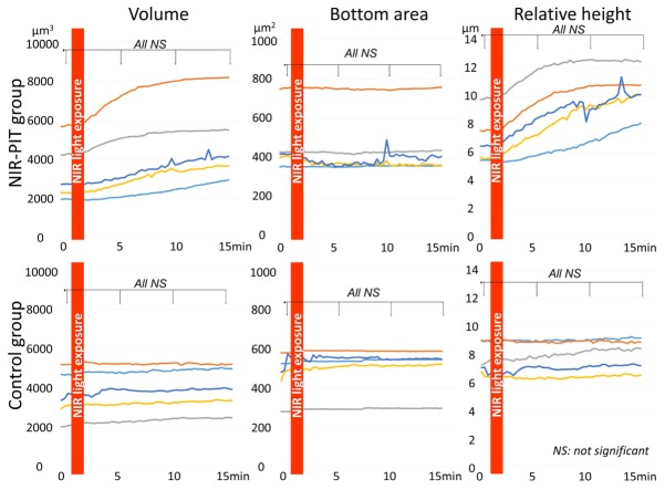
In the NIR-PIT group cell volume and relative height of cell increased gradually after NIR light exposure. However, there was no significant difference (p = 0.70, 0.49 and 0.38 at 5, 10, and 15 min after NIR-light exposure for cell volume, p = 0.51, 0.13 and 0.06 at 5, 10 and 15 min after NIR-light exposure for relative height of cell, respectively). The bottom area of the cells did not change after NIR light exposure (p = 0.75, 0.75 and 0.77 at 5, 10, and 15 min after NIR-light exposure, respectively) (Fig. 4).
Fig. 4.
Morphological changes of 3T3/HER2 cells after NIR-PIT. In the NIR-PIT group cell volume and relative height of cell increased gradually after NIR light exposure although the changes did not reach significance. In the control group cell volume, bottom area of cell, and relative height of cell did not change after NIR light exposure.
In the control group none of the parameters changed after NIR light exposure (p = 0.69, 0.69 and 0.64 at 5, 10, and 15 min after NIR-light exposure for cell volume, p = 0.92, 0.92 and 0.92 at 5, 10, and 15 min after NIR-light exposure for bottom area of cell, p = 0.82, 0.81 and 0.71 at 5, 10, and 15 min after NIR-light exposure for relative height of cell, respectively) (Fig. 4).
3.3.2 MDA-MB-468 cells
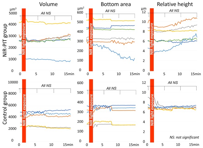
In the NIR-PIT group cell volume did not change after NIR light exposure (p = 0.89, 0.89 and 0.87 at 5, 10, and 15 min after NIR-light exposure, respectively). On the other hand, the bottom area of the cells decreased while the relative height of the cells increased gradually after NIR light exposure. However, there was no significant difference for either of them (p = 0.73, 0.68 and 0.60 at 5, 10, and 15 min after NIR-light exposure for bottom area of cell, p = 0.90, 0.85 and 0.66 at 5, 10, and 15 min after NIR-light exposure for relative height of cell, respectively) (Fig. 5).
Fig. 5.
Morphological changes of MDA-MB-468 cells after NIR-PIT. In the NIR-PIT group cell volume did not change after NIR light exposure. On the other hand, the bottom area of cell attachment decreased while relative height of cell increased gradually after NIR light exposure. However, these findings did not reach significance. In the control group volume, bottom area, and relative height of cell did not change after NIR light exposure.
In the control group volume, bottom area, and relative height of the cells did not change after NIR light exposure (p = 0.78, 0.81 and 0.81 at 5, 10, and 15 min after NIR-light exposure for cell volume, p = 0.87, 0.88 and 0.83 at 5, 10, and 15 min after NIR-light exposure for bottom area of cell, p = 1.00, 1.00 and 1.00 at 5, 10, and 15 min after NIR-light exposure for relative height of cell, respectively) (Fig. 5).
4. Discussion
3D LC-QPM is a new method of live cell imaging that provides a method of studying cell membrane dynamics. Our results demonstrate that 3D LC-QPM readily depicts active filopodia on 3T3/HER2 and MDA-MB-468 live cells. Prior live cell microscopy methods rely on genetically transduced fluorescent proteins which generally do not label the membrane. Moreover, fluorescent techniques have a number of drawbacks, including photobleaching which prohibits long-term studies, production of free radical singlet oxygen species which can damage live cells, finally, the inherent changes in cell surface chemistry which render results difficult to interpret [21]. Thus, 3D LC-QPM, provides a useful method for evaluating the cell membrane including the fate of filopodia.
During 3D LC-QPM of live cells before and after NIR-PIT we observed dynamic reductions in the number of filopodia in 3T3/HER2 and MDA-MB-468 cells where both the number and visual score of filopodia decreased immediately after NIR light exposure. Significant differences were observed only 5 min after NIR light exposure in the NIR-PIT group but not in the control group. Filopodial extrusions at the leading edge of a migrating cells have been reported [9]. Cell migration is important in cancer progression including in forming metastases and facilitating angiogenesis [22–24]. Thus, our results indicate that immediately after NIR-PIT profound changes in filopodia, an important structure for cancer progression, are observed.
Other morphological changes in the treated cells were observed but were not as consistent as the changes in the filopedia. Morphological changes, including cell volume, bottom area, and relative height of the cell were measured with 3D LC-QPM. In the NIR-PIT group the volume of 3T3/HER2 cells increased gradually after NIR light exposure although it did not reach significance. Within minutes, cells treated with NIR-PIT rapidly increase in volume leading to rupture of the cell membrane, and extrusion of cell contents into the extracellular space [2–5] indicating a necrotic rather than apoptotic cell death [6–8]. Therefore, the rapid increase in 3T3/HER2 cell volume indicated that NIR-PIT induces necrotic cell death. Moreover, the bottom area of MDA-MB-468 cell decreased gradually after NIR light exposure in the NIR-PIT group, suggesting that cellular attachment to the slide became weaker because of cell membrane damage induced by NIR-PIT.
The temporal course of membrane changes after NIR-PIT clearly indicate that the elimination of filopodia is the first demonstrable event in cell membrane damage. Other morphological changes such as changes in volume or decrements in bottom area of cellular attachment started immediately after NIR light exposure, but did not reach significant differences until 15 min after NIR light exposure. On the other hand, the number of or visual score of filopodia started to decrease immediately after NIR light exposure reaching significance within only 5 min after NIR light exposure. Thus, changes in filopodia due to cell membrane damage by NIR-PIT precedes all other morphological changes and therefore, are an early marker of a pharmacodynamics effect.
Not all cells demonstrates filopodia. For instance, filopedia were not detected in A431, SKOV3, and N87 cells. However, it should be noted that 3D LC-QPM cannot fully evaluate the bottom area of the cells, about 1 μm from the surface of a glass slide, due to specular reflection from the glass even if using a glass slide to which both an AR coating for the bandwidth of 550-950 nm and a reflection enhancement coating were applied. Thus, filopodia in these cells, localized around the bottom area of the cell culture, may not have been detected. Live cell membrane imaging techniques which can evaluate the bottom surface of cells may be needed for these cells.
One of limitation of 3D LC-QPM is that only cultured cells can be evaluated. On the other hand, dynamic live cell imaging is already well developed especially in vivo using genetically introduced fluorescent proteins basically [25–31] and some label-free in vivo studies has also been reported [32,33]. However, the study of cellular membrane dynamics has been stymied because it is difficult to genetically modify the cell membrane to introduce fluorescent proteins. Thus, 3D LC-QPM is supposed to be useful because of its possibility of evaluation of cell membrane without any label even if it is evaluated only in the in vitro setting. Moreover, our result revealed that changes in filopodia preceded all other morphological changes by NIR-PIT, indicating that alteration of filopodia may be an early indicator of cell membrane damage. Thus, evaluation of change of fiolopodia including counting the number of filopodia using 3D LC-QPM should be beneficial for evaluation of cell membrane damage due to various condition at early time point.
In conclusion, observation with 3D LC-QPM revealed that filopodia rapidly disappeared after NIR-PIT representing the first observable change in cells with filopodia. 3D LC-QPM is useful for imaging earlier cell membrane damage induced by NIR-PIT.
Acknowledgements
This research was supported by the Intramural Research Program of the National Institute of Health, National Cancer Institute, Center for Cancer Research.
References and links
- 1.Mitsunaga M., Ogawa M., Kosaka N., Rosenblum L. T., Choyke P. L., Kobayashi H., “Cancer cell-selective in vivo near infrared photoimmunotherapy targeting specific membrane molecules,” Nat. Med. 17(12), 1685–1691 (2011). 10.1038/nm.2554 [DOI] [PMC free article] [PubMed] [Google Scholar]
- 2.Mitsunaga M., Nakajima T., Sano K., Choyke P. L., Kobayashi H., “Near-infrared theranostic photoimmunotherapy (PIT): repeated exposure of light enhances the effect of immunoconjugate,” Bioconjug. Chem. 23(3), 604–609 (2012). 10.1021/bc200648m [DOI] [PMC free article] [PubMed] [Google Scholar]
- 3.Sato K., Watanabe R., Hanaoka H., Harada T., Nakajima T., Kim I., Paik C. H., Choyke P. L., Kobayashi H., “Photoimmunotherapy: comparative effectiveness of two monoclonal antibodies targeting the epidermal growth factor receptor,” Mol. Oncol. 8(3), 620–632 (2014). 10.1016/j.molonc.2014.01.006 [DOI] [PMC free article] [PubMed] [Google Scholar]
- 4.Nakajima T., Sano K., Mitsunaga M., Choyke P. L., Kobayashi H., “Real-time monitoring of in vivo acute necrotic cancer cell death induced by near infrared photoimmunotherapy using fluorescence lifetime imaging,” Cancer Res. 72(18), 4622–4628 (2012). 10.1158/0008-5472.CAN-12-1298 [DOI] [PMC free article] [PubMed] [Google Scholar]
- 5.Shirasu N., Yamada H., Shibaguchi H., Kuroki M., Kuroki M., “Potent and specific antitumor effect of CEA-targeted photoimmunotherapy,” Int. J. Cancer 135(11), 2697–2710 (2014). 10.1002/ijc.28907 [DOI] [PubMed] [Google Scholar]
- 6.Kerr J. F., “Shrinkage necrosis: a distinct mode of cellular death,” J. Pathol. 105(1), 13–20 (1971). 10.1002/path.1711050103 [DOI] [PubMed] [Google Scholar]
- 7.Willingham M. C., “Cytochemical methods for the detection of apoptosis,” J. Histochem. Cytochem. 47(9), 1101–1109 (1999). 10.1177/002215549904700901 [DOI] [PubMed] [Google Scholar]
- 8.Ziegler U., Groscurth P., “Morphological features of cell death,” News Physiol. Sci. 19(3), 124–128 (2004). 10.1152/nips.01519.2004 [DOI] [PubMed] [Google Scholar]
- 9.Arjonen A., Kaukonen R., Ivaska J., “Filopodia and adhesion in cancer cell motility,” Cell Adhes. Migr. 5(5), 421–430 (2011). 10.4161/cam.5.5.17723 [DOI] [PMC free article] [PubMed] [Google Scholar]
- 10.Zhang H., Berg J. S., Li Z., Wang Y., Lang P., Sousa A. D., Bhaskar A., Cheney R. E., Strömblad S., “Myosin-X provides a motor-based link between integrins and the cytoskeleton,” Nat. Cell Biol. 6(6), 523–531 (2004). 10.1038/ncb1136 [DOI] [PubMed] [Google Scholar]
- 11.Faix J., Rottner K., “The making of filopodia,” Curr. Opin. Cell Biol. 18(1), 18–25 (2006). 10.1016/j.ceb.2005.11.002 [DOI] [PubMed] [Google Scholar]
- 12.Eilken H. M., Adams R. H., “Dynamics of endothelial cell behavior in sprouting angiogenesis,” Curr. Opin. Cell Biol. 22(5), 617–625 (2010). 10.1016/j.ceb.2010.08.010 [DOI] [PubMed] [Google Scholar]
- 13.Jacquemet G., Hamidi H., Ivaska J., “Filopodia in cell adhesion, 3D migration and cancer cell invasion,” Curr. Opin. Cell Biol. 36, 23–31 (2015). 10.1016/j.ceb.2015.06.007 [DOI] [PubMed] [Google Scholar]
- 14.Petrie R. J., Yamada K. M., “At the leading edge of three-dimensional cell migration,” J. Cell Sci. 125(24), 5917–5926 (2012). 10.1242/jcs.093732 [DOI] [PMC free article] [PubMed] [Google Scholar]
- 15.Shibue T., Brooks M. W., Weinberg R. A., “An integrin-linked machinery of cytoskeletal regulation that enables experimental tumor initiation and metastatic colonization,” Cancer Cell 24(4), 481–498 (2013). 10.1016/j.ccr.2013.08.012 [DOI] [PMC free article] [PubMed] [Google Scholar]
- 16.Chalfie M., Tu Y., Euskirchen G., Ward W. W., Prasher D. C., “Green fluorescent protein as a marker for gene expression,” Science 263(5148), 802–805 (1994). 10.1126/science.8303295 [DOI] [PubMed] [Google Scholar]
- 17.Yamauchi T., Iwai H., Miwa M., Yamashita Y., “Low-coherent quantitative phase microscope for nanometer-scale measurement of living cells morphology,” Opt. Express 16(16), 12227–12238 (2008). 10.1364/OE.16.012227 [DOI] [PubMed] [Google Scholar]
- 18.Yamauchi T., Iwai H., Yamashita Y., “Label-free imaging of intracellular motility by low-coherent quantitative phase microscopy,” Opt. Express 19(6), 5536–5550 (2011). 10.1364/OE.19.005536 [DOI] [PubMed] [Google Scholar]
- 19.Sano K., Nakajima T., Choyke P. L., Kobayashi H., “Markedly enhanced permeability and retention effects induced by photo-immunotherapy of tumors,” ACS Nano 7(1), 717–724 (2013). 10.1021/nn305011p [DOI] [PMC free article] [PubMed] [Google Scholar]
- 20.Wan Y., Otsuna H., Chien C. B., Hansen C., “FluoRender: An Application of 2D Image Space Methods for 3D and 4D Confocal Microscopy Data Visualization in Neurobiology Research,” IEEE Pac. Vis. Symp. 865, 201–208 (2012). [DOI] [PMC free article] [PubMed] [Google Scholar]
- 21.Sugiyama N., Asai Y., Yamauchi T., Kataoka T., Ikeda T., Iwai H., Sakurai T., Mizuguchi Y., “Label-free characterization of living human induced pluripotent stem cells by subcellular topographic imaging technique using full-field quantitative phase microscopy coupled with interference reflection microscopy,” Biomed. Opt. Express 3(9), 2175–2183 (2012). 10.1364/BOE.3.002175 [DOI] [PMC free article] [PubMed] [Google Scholar]
- 22.Nürnberg A., Kitzing T., Grosse R., “Nucleating actin for invasion,” Nat. Rev. Cancer 11(3), 177–187 (2011). 10.1038/nrc3003 [DOI] [PubMed] [Google Scholar]
- 23.Muller P. A., Vousden K. H., Norman J. C., “p53 and its mutants in tumor cell migration and invasion,” J. Cell Biol. 192(2), 209–218 (2011). [DOI] [PMC free article] [PubMed] [Google Scholar]
- 24.Saharinen P., Eklund L., Pulkki K., Bono P., Alitalo K., “VEGF and angiopoietin signaling in tumor angiogenesis and metastasis,” Trends Mol. Med. 17(7), 347–362 (2011). 10.1016/j.molmed.2011.01.015 [DOI] [PubMed] [Google Scholar]
- 25.Hoffman R. M., “In vivo imaging with fluorescent proteins: the new cell biology,” Acta Histochem. 106(2), 77–87 (2004). 10.1016/j.acthis.2004.02.001 [DOI] [PubMed] [Google Scholar]
- 26.Yamamoto N., Jiang P., Yang M., Xu M., Yamauchi K., Tsuchiya H., Tomita K., Wahl G. M., Moossa A. R., Hoffman R. M., “Cellular dynamics visualized in live cells in vitro and in vivo by differential dual-color nuclear-cytoplasmic fluorescent-protein expression,” Cancer Res. 64(12), 4251–4256 (2004). 10.1158/0008-5472.CAN-04-0643 [DOI] [PubMed] [Google Scholar]
- 27.Yamauchi K., Yang M., Jiang P., Yamamoto N., Xu M., Amoh Y., Tsuji K., Bouvet M., Tsuchiya H., Tomita K., Moossa A. R., Hoffman R. M., “Real-time in vivo dual-color imaging of intracapillary cancer cell and nucleus deformation and migration,” Cancer Res. 65(10), 4246–4252 (2005). 10.1158/0008-5472.CAN-05-0069 [DOI] [PubMed] [Google Scholar]
- 28.Hoffman R. M., Yang M., “Subcellular imaging in the live mouse,” Nat. Protoc. 1(2), 775–782 (2006). 10.1038/nprot.2006.109 [DOI] [PubMed] [Google Scholar]
- 29.Yamauchi K., Yang M., Jiang P., Xu M., Yamamoto N., Tsuchiya H., Tomita K., Moossa A. R., Bouvet M., Hoffman R. M., “Development of real-time subcellular dynamic multicolor imaging of cancer-cell trafficking in live mice with a variable-magnification whole-mouse imaging system,” Cancer Res. 66(8), 4208–4214 (2006). 10.1158/0008-5472.CAN-05-3927 [DOI] [PubMed] [Google Scholar]
- 30.R. M. Hoffman, In vivo Cellular Imaging Using Fluorescent Proteins: Methods and Protocols (Humana Press, 2012) [Google Scholar]
- 31.Momiyama M., Suetsugu A., Kimura H., Chishima T., Bouvet M., Endo I., Hoffman R. M., “Dynamic subcellular imaging of cancer cell mitosis in the brain of live mice,” Anticancer Res. 33(4), 1367–1371 (2013). [PubMed] [Google Scholar]
- 32.Uchugonova A., Hoffman R. M., Koenig K., “Stem cell imaging in living animals,” Imaging Microscopy 3, 44–46 (2013). [Google Scholar]
- 33.Uchugonova A., Cao W., Hoffman R. M., Koenig K., “Comparison of label-free and GFP multiphoton imaging of hair follicle-associated pluripotent (HAP) stem cells in mouse whiskers,” Cell Cycle 14(21), 3430–3433 (2015). 10.1080/15384101.2015.1090064 [DOI] [PMC free article] [PubMed] [Google Scholar]


