Abstract
Multi-layer structures with soft (compliant) interlayers have been widely used in flexible electronics and photonics as an effective design for reducing interactions among the hard (stiff) layers and thus avoiding the premature failure of an entire device. The analytic model for bending of such a structure has not been well established due to its complex mechanical behaviour. Here, we present a rational analytic model, without any parameter fitting, to study the bending of a multi-layer structure on a cylinder, which is often regarded as an important approach to mechanical reliability testing of flexible electronics and photonics. For the first time, our model quantitatively reveals that, as the key for accurate strain control, the splitting of the neutral mechanical plane depends not only on the relative thickness of the middle layer, but also on the length-to-thickness ratio of the multi-layer structure. The model accurately captures the key quantities, including the axial strains in the top and bottom layers, the shear strain in the middle layer and the locations of the neutral mechanical planes of the top and bottom layers. The effects of the length of the multi-layer and the thickness of the middle layer are elaborated. This work is very useful for the design of multi-layer structure-based flexible electronics and photonics.
Keywords: neutral mechanical plane, multi-layer structure, flexible electronics, structure design
1. Introduction
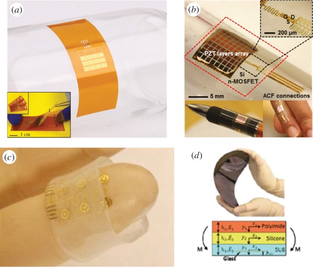
Multi-layer structures are encountered in various engineering applications such as aerospace vehicles, marine vessels and civil infrastructures. Such structures have been investigated extensively in recent years, focusing on the static and dynamic behaviour, mechanical failure, structural design and manufacture [1–4]. The most popular multi-layer structures are lightweight sandwich panels that are based on two stiff face sheets separated by a soft foam core and that have unique mechanical properties such as high rigidity, high impact energy absorption, stable deformation mode and adaptation to loading conditions. In flexible electronics and photonics, multi-layer structures with both soft (compliant) and hard (stiff) materials are also widely used in order to reduce the strains in the hard layers, which are often composed of functional devices [5–7]. Such applications include flexible piezoelectric mechanical energy harvesters (MEHs) [8] (figure 1a), conformable piezoelectric pressure sensors [9] (figure 1b), finger-tip electronics [10] (figure 1c), flexible glass photonic devices [11] (figure 1d), etc. However, incorrect stacking of the layers would cause premature failure of the entire device. Therefore, it is necessary to explore effective designs of the laminated structures so that they can undergo large deformation during fabrication and use.
Figure 1.
(a) Stacking and bending test of three hard PZT-based piezoelectric MEHs. (b) Conformable piezoelectric pressure sensor with multi-layer structures.(c) Finger-tip electronics with multi-layer structures. (d) Flexible glass photonic device with multi-layer structures. (Online version in colour.)
Recently, a novel local-neutral-axis design (figure 1d) was implemented to render the structure highly mechanically flexible, enabling repeated bending of the photonic device down to sub-millimetre bending radii without any measurable degradation in optical performance [11]. This design is also referred to as the splitting of the neutral mechanical plane [8]. It is known that the neutral mechanical plane is a layer within a structure where the material is not under stress, either compression or tension. That is, strain in the neutral mechanical plane is zero when the structure bends. For the design of flexible electronics and photonics, one always expects accurate strain control in the brittle device. Therefore, it is very useful to split the neutral mechanical plane into each hard layer where the brittle device is placed. In this way, the strength of each layer is reached almost simultaneously. This could avoid premature failure. Some simplified theoretical models were developed to quantitatively study the pure bending and buckling behaviour of the multi-layer structures, where a large modulus mismatch among the different layers is a distinctive feature [8,11–13]. Actually, previous studies simply incorporated the effects of the thickness and elastic modulus, and there have been no discussions on the effects of the length of the structure due to the modelling complexity induced by coupling deformation. However, as illustrated in the following, our finite-element analysis (FEA) reveals that the influence of the length cannot be neglected. Therefore, an accurate mechanics model incorporating the length effect is critically needed to comprehensively grasp the mechanical behaviour, which can provide guidelines for the design of such structures against mechanical failure.
In this paper, we establish an approach to accurate analytic modelling of multi-layers with moduli of very different orders of magnitude (e.g. silicon and polydimethylsiloxane, which have elastic moduli of five orders of magnitude difference), where the classical beam theory [14] with plane cross-sectional assumption fails. A very important application of the model is the characterization of the bendability of the flexible electronics and photonics, in which the key index is the minimum bending radius of the device. This could be realized by attaching the device to cylindrical surfaces with different radii. The index is the minimum cylindrical radius at which the device remains intact. Such a bending test is illustrated in figure 1a, where a stack of three hard lead zirconate titanate (PZT)-based piezoelectric MEHs are laminated, with a soft adhesive in between [8], and bent to fit a glass cylinder. For convenience, we focus on the three-layer sandwich structure, which has two hard layers with a soft adhesive in between. The analytic model is established and an accurate solution is obtained to quantitatively capture the structural behaviour as well as to provide guidelines for the refined design of flexible devices against premature failure.
2. The model
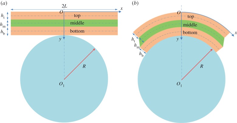
Figure 2 shows a three-layer sandwich structure with length 2L and thicknesses ht, hm and hb from top to bottom at the natural, stress-free state (figure 2a) and the deformed state on a cylinder with radius R (figure 2b). Young's moduli and Poisson's ratios for the layers are Et, Em and Eb, and vt, vm and vb, respectively. The middle layer is much softer than the other layers and serves as the shear lag whose large shear deformation is the dominant mechanical behaviour. This is the main difference from multi-layers with similar elastic properties. Owing to the symmetry of the structure, only the right half model with length L is considered.
Figure 2.
Theoretical model of a three-layer sandwich structure. (a) The natural, stress-free state. (b) The deformed state on a cylinder. (Online version in colour.)
Multi-layer structures for flexible electronics and photonics are generally long and thin [15–18]. Therefore, the thickness change of the layers is neglected. As shown in figure 2, x is the curvilinear coordinate along the central axis of a layer, with the origin O at the axis centre. Let ut and ub denote the displacement increments at the central axes of the top and bottom layers during deformation. The corresponding membrane strains (εt and εb) and bending curvatures (κt and κb) are
| 2.1 |
As shown in figure 3, the shear strain of the middle layer, γm, is obtained by
| 2.2 |
The variational approach [19,20] is used to yield the governing equations in terms of the displacements. The total elastic energy, U, of the right half structure consists of the membrane energy and bending energy of the top and bottom layers as well as the shear energy of the middle layer. We have
| 2.3 |
where , and , are the beam theory-based effective bending stiffnesses and tensile stiffnesses of the top and bottom layers, respectively [21]; is the shear modulus of the middle layer. Substituting equations (2.1) and (2.2) in equation (2.3), we have
| 2.4 |
Variation of equation (2.4) δU=0 gives the governing equations
| 2.5 |
and the boundary conditions
| 2.6 |
where a=(R+hb+hm/2)/(R+hb+hm+ht/2) and b=(R+hb+hm/2)/(R+hb/2). Equation (2.6) implies that there is no axial displacement at the plane of symmetry and no axial strain at the right-hand end of the top and bottom layers.
Figure 3.
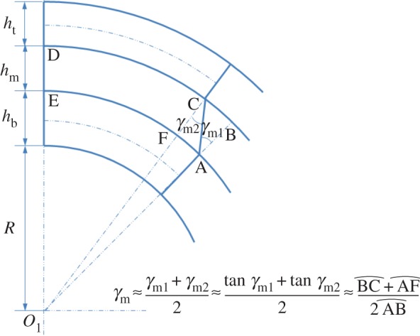
Schematic illustration of the shear strain of the middle layer. (Online version in colour.)
The general solution of equation (2.5) is
| 2.7 |
where and . The constants C1–C4 are determined by substituting equation (2.7) into equation (2.6), which yields
| 2.8 |
Thus ut and ub are obtained as
| 2.9 |
Substituting equation (2.9) into equations (2.1) and (2.2), we obtain the membrane strains of the top and bottom layers as well as the shear strain of the middle layer,
| 2.10 |
The mode of deformation for the top and bottom layers is that of the slender beam because they are hard, long and thin; this model is known as the Euler–Bernoulli beam, where the axial strains are linearly distributed [22]. This yields
| 2.11 |
where y is the distance in the normal direction from the top surface of the multi-layers. The locations of the neutral mechanical planes of the top and bottom layers, yt and yb, are determined by equating to zero the strains in equation (2.11), by which we have
| 2.12 |
For simplification, we now focus on the case in which Et=Eb=E, ht=hb=h and vt=vb=vm=v. We have
| 2.13 |
where . The membrane strains of the top and bottom layers as well as the shear strain of the middle layer become
| 2.14 |
where ρ=L/h and . The normalized locations of the neutral mechanical planes of the top and bottom layers are
| 2.15 |
3. Results and discussion
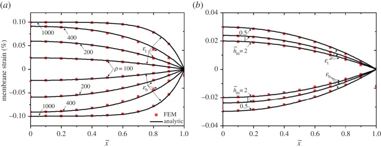
A typical multi-layer structure with the geometric parameters and mechanical properties R=0.014 m, h=10−5 m, E=1000 MPa, Em=100 KPa and v=0.4 is examined. The membrane strains in both the top and bottom layers are plotted in figure 4 for and ρ=100, 200, 400, 1000 (figure 4a), and for ρ=100 and , 1, 2 (figure 4b). Excellent agreement is observed between our analytic model and the FEA results (see appendix A for details of the FEA modelling). As shown in figure 4a, the membrane strain is approximately linearly distributed in the hard layers for a relatively short structure with small ρ and approaches the constant for a relatively long structure with large ρ except around the end of the structure. The membrane strain increases with an increase of ρ (figure 4a) and decreases with (figure 4b). This indicates that the thick middle layer and the short multi-layer structure help to reduce the membrane strains in the hard layers.
Figure 4.
Membrane strain distribution in both the top and bottom layers for (a) and (b) ρ=100. (Online version in colour.)
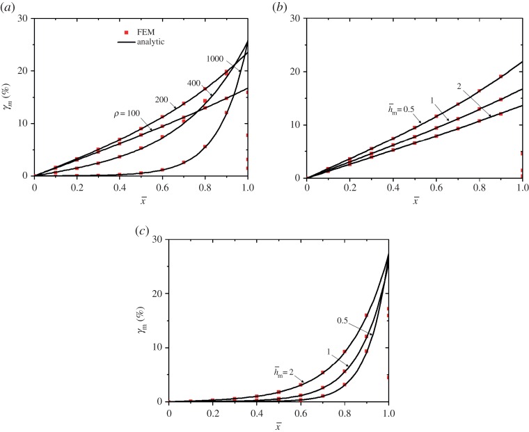
Figure 5 shows the shear strain distribution in the soft middle layer for and ρ=100, 200, 400, 1000 (figure 5a), and for , 1, 2 and ρ=100 (figure 5b) and 1000 (figure 5c). FEA perfectly validates the analytic results. At a given , the longer multi-layer structure helps to reduce the shear strain around (figure 5a). It is interesting to observe that the shear strain decreases with an increase of for a relatively short structure (figure 5b), but increases with around for a relatively long structure (figure 5c). In general, a thick middle layer and a short multi-layer structure help to increase the shear strain in most of the middle layer, which benefits the transfer of strain energy to the middle layer such that the strains in the hard layers diminish.
Figure 5.
Shear strain distribution in the middle layer for (a) , (b) ρ=100 and (c) ρ=1000. (Online version in colour.)
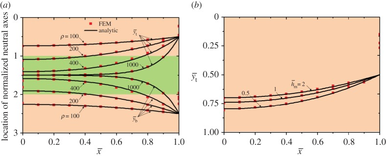
The normalized locations of the neutral mechanical planes are plotted in figure 6 for and ρ=100, 200, 400, 1000 (figure 6a), and for ρ=100 and , 1, 2 (figure 6b). The analytic solutions agree very well with FEA. It is seen that the neutral mechanical planes shift towards the centre of the hard layers with decreasing ρ and with increasing , which implies that a short and thick adhesive helps to split the neutral mechanical plane and thus could avoid premature failure of the entire device.
Figure 6.
Normalized locations of the neutral mechanical planes in (a) the top and bottom layers for and in (b) the top layer for ρ=100. (Online version in colour.)
A meaningful discussion of the extreme cases from equation (2.15) is helpful in the design of the multi-layer structure. (i) The middle layer is soft enough such that Em→0 and thus d→0. In this case, and , which means that both the top and bottom layers bend as independent single layers and splitting of the neutral mechanical plane is achieved. (ii) The middle layer is hard enough such that and thus . In this case, and for R≫h and hm, which means that the plane section holds for the entire multi-layer structure and there is only one neutral mechanical plane. (iii) The length of the structure is much larger than its thickness such that . In this case, the result is the same as that in case (ii). (iv) The length of the structure is much smaller than its thickness such that ρ→0. In this case, the result is the same as that in case (i). (v) The thickness of the middle layer is much smaller than that of the top and bottom layers such that hm→0. In this case, the result is the same as that in case (ii).
It should be noted that, taking y=0 and hm+ht+hb in equation (2.11), respectively, the axial strains at the top and bottom surfaces of the multi-layers are readily obtained:
| 3.1 |
This is very useful to rapidly predict the extreme strains in the structure.
4. Conclusion
In summary, we have established a sufficiently accurate, FEA-validated analytic model for cylindrical bending of a multi-layer structure with soft interlayers for flexible electronics and photonics, in which we incorporate the length effect, for the first time, in depicting the mechanical behaviour of such structures. The axial strains in the top and bottom layers as well as the shear strain in the middle layer are analytically obtained and the locations of the neutral mechanical planes of the top and bottom layers are pinpointed. We analyse a typical multi-layer structure in detail to reveal the effects of the normalized length of the multi-layers and normalized thickness of the middle layer. In general, a short and thick adhesive helps to split the neutral mechanical plane and thus can avoid the premature failure of the entire device. It should be noted that the three-layer sandwich structure is adopted for demonstration and similar structures with more layers can be analysed with the same method, which will yield the same conclusion. The work in this paper is expected to serve as a benchmark model for designing multi-layers with very different elastic properties.
Appendix A. Finite-element analysis modelling
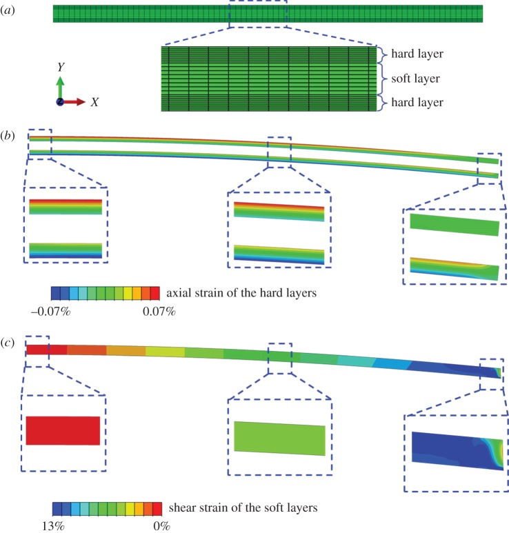
FEA modelling using the ABAQUS software package was conducted to validate the analytic results of equations (2.12) and (2.13). The bottom surface of the three-dimensional sandwich structure was attached to an extremely hard three-dimensional shell without friction or delamination. The shell was bent to realize the bending of the multi-layers. With the same length and thickness as those in the analytic model for the multi-layers, the symmetric boundary condition was imposed on the FEA model and only the right half was analysed. The displacement along the width direction was restricted to realize the plane strain state. The displacement along the length direction was restricted on the left-hand side of the multi-layers while the left-hand side of the shell was clamped. In-plane rotation with angle L/R was imposed on the right-hand side of the shell. Without any assumption of plane section or shear lag, the 20-node quadratic brick element C3D20R was employed for the multi-layer structure and the 8-node doubly curved thick shell element S8R was adopted for the shell. As an example, figure 7a shows the finite-element meshes of all of the multi-layers for and ρ=100. The numbers of uniform grids for each layer are 80 in the length direction (x), eight in the thickness direction (y), and one in the width direction (z). Figure 7b,c shows the axial strain and shear strain distribution, respectively.
Figure 7.
The finite-element meshes and strain distribution of the model (, ρ=100). (a) The mesh of the multi-layers. (b) The axial strain distribution of the hard layers. (c) The shear strain distribution of the soft layer. (Online version in colour.)
Authors' contributions
All authors conceived the idea of this work, performed the theoretical analysis and the numerical simulation, wrote the manuscript and gave final approval for publication.
Competing interests
The authors declare no competing financial interests.
Funding
Y.S. and R.L. acknowledge support from the National Natural Science Foundation of China (grant nos 11572323 and 11302038). Y.S. also acknowledges support from the Chinese Academy of Sciences via the ‘Hundred Talent program’.
References
- 1.Allen HG. 1969. Analysis and design of structural sandwich panels. Oxford, UK: Pergamon Press. [Google Scholar]
- 2.Zhu F, Zhao L, Lu G, Wang Z. 2008. Deformation and failure of blast-loaded metallic sandwich panels—experimental investigations. Int. J. Impact Eng. 35, 937–951. (doi:10.1016/j.ijimpeng.2007.11.003) [Google Scholar]
- 3.Li R, Kardomateas GA. 2008. Nonlinear high-order core theory for sandwich plates with orthotropic phases. AIAA J. 46, 2926–2934. (doi:10.2514/1.37430) [Google Scholar]
- 4.Hohe J, Librescu L, Oh SY. 2006. Dynamic buckling of flat and curved sandwich panels with transversely compressible core. Compos. Struct. 74, 10–24. (doi:10.1016/j.compstruct.2005.03.003) [Google Scholar]
- 5.Kim D-H, Lu N, Huang Y, Rogers JA. 2012. Materials for stretchable electronics in bioinspired and biointegrated devices. MRS Bull. 37, 226–235. (doi:10.1557/mrs.2012.36) [Google Scholar]
- 6.Rogers JA, Someya T, Huang Y. 2010. Materials and mechanics for stretchable electronics. Science 327, 1603–1607. (doi:10.1126/science.1182383) [DOI] [PubMed] [Google Scholar]
- 7.Kim D-H, Xiao J, Song J, Huang Y, Rogers JA. 2010. Stretchable, curvilinear electronics based on inorganic materials. Adv. Mater. 22, 2108–2124. (doi:10.1002/adma.200902927) [DOI] [PubMed] [Google Scholar]
- 8.Su Y, Li S, Li R, Dagdeviren C. 2015. Splitting of neutral mechanical plane of conformal, multilayer piezoelectric mechanical energy harvester. Appl. Phys. Lett. 107, 041905 (doi:10.1063/1.4927677) [Google Scholar]
- 9.Dagdeviren C. et al 2014. Conformable amplified lead zirconate titanate sensors with enhanced piezoelectric response for cutaneous pressure monitoring. Nat. Commun. 5, 4496 (doi:10.1038/ncomms5496) [DOI] [PubMed] [Google Scholar]
- 10.Su Y, Li R, Cheng H, Ying M, Bonifas AP, Hwang K-C, Rogers JA, Huang Y. 2013. Mechanics of finger-tip electronics. J. Appl. Phys. 114, 164511 (doi:10.1063/1.4828476) [DOI] [PMC free article] [PubMed] [Google Scholar]
- 11.Li L, Lin H, Qiao S, Zou Y, Danto S, Richardson K, Musgraves JD, Lu N, Hu J. 2014. Integrated flexible chalcogenide glass photonic devices. Nat. Photonics 8, 643–649. (doi:10.1038/nphoton.2014.138) [Google Scholar]
- 12.Shi Y, Rogers JA, Gao C, Huang Y. 2014. Multiple neutral axes in bending of a multiple-layer beam with extremely different elastic properties. Trans. ASME, J. Appl. Mech. 81, 114501 (doi:10.1115/1.4028465) [Google Scholar]
- 13.Lu N, Yang S, Qiao S. 2014. Mechanics of flexible electronics and photonics based on inorganic micro- and nanomaterials. In Micro- and nanotechnology sensors, systems, and applications VI (eds T George, MS Islam, AK Dutta). Proceedings of SPIE, vol. 9083. Bellingham, WA: SPIE. [Google Scholar]
- 14.Timoshenko S. 1930. Strength of materials. New York, NY: D. Van Nostrand Company. [Google Scholar]
- 15.Lee YC, Liu TS. 2014. Deformation of multilayer flexible electronics subjected to torque. Exp. Tech. 38, 13–20. (doi:10.1111/j.1747-1567.2011.00780.x) [Google Scholar]
- 16.Lin KL, Jain K. 2009. Design and fabrication of stretchable multilayer self-aligned interconnects for flexible electronics and large-area sensor arrays using excimer laser photoablation. IEEE Electron Devices Lett. 30, 14–17. (doi:10.1109/LED.2008.2008665) [Google Scholar]
- 17.Yu S, Zhang W, Li L, Xu D, Dong H, Jin Y. 2013. Transparent conductive Sb-doped SnO2/Ag multilayer films fabricated by magnetron sputtering for flexible electronics. Acta Mater. 61, 5429–5436. (doi:10.1016/j.actamat.2013.05.031) [Google Scholar]
- 18.Zheng J, Tucker MB, Teng L. 2011. Failure mechanics of organic-inorganic multilayer permeation barriers in flexible electronics. Compos. Sci. Technol. 71, 365–372. (doi:10.1016/j.compscitech.2010.12.003) [Google Scholar]
- 19.Ekeland I. 1974. Variational principle. J. Math. Anal. Appl. 47, 324–353. (doi:10.1016/0022-247X(74)90025-0) [Google Scholar]
- 20.Seliger RL, Whitham GB. 1968. Variational principles in continuum mechanics. Proc. R. Soc. Lond. A 305, 1–25. (doi:10.1098/rspa.1968.0103) [Google Scholar]
- 21.Almeida PAD, Ferreira CAT. 1998. Determination of the effective bending stiffness of nailed laminated wood beams. In Proc. 5th World Conf. on Timber Engineering, Montreux, Switzerland, 17–20 August 1998, vol. 1, pp. 425–431. Lausanne, Switzerland: Presses Polytechniques et universitaires romandes.
- 22.Timoshenko S. 1953. History of strength of materials. New York, NY: McGraw-Hill Company. [Google Scholar]


