Abstract
AIM
To assess and compare the morphology of corneal flaps created by the Wavelight FS200 and Intralase FS60 femtosecond lasers in laser in situ keratomileusis (LASIK).
METHODS
Four hundred eyes of 200 patients were enrolled in this study and divided into Wavelight FS200 groups (200 eyes) and Intralase FS60 groups (200 eyes). Fourier-domain optical coherence tomography (RTVue OCT) was used to measure the corneal flap thickness of 36 specified measurements on each flap one week after surgery. Results were used to analyze the regularity, uniformity and accuracy of the two types of LASIK flaps.
RESULTS
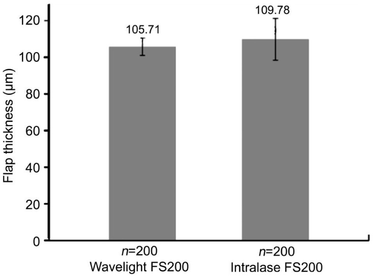
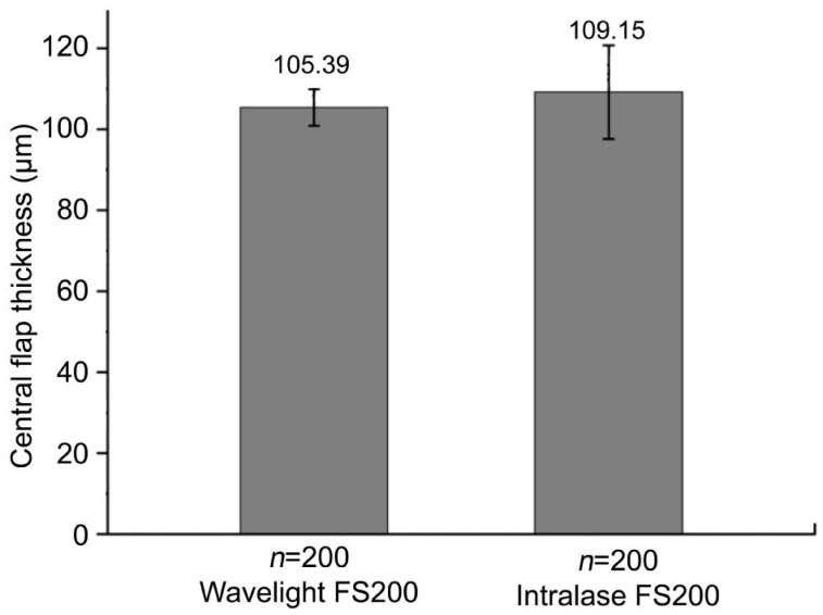
The mean thickness of corneal flap and central flap was 105.71±4.72 µm and 105.39±4.50 µm in Wavelight FS200 group and 109.78±11.42 µm and 109.15 ±11.59 µm in Intralase FS60 group, respectively. The flaps made with the Wavelight FS200 femtosecond laser were thinner than those created by the Intralase FS60 femtosecond laser (P=0.000). Corneal flaps in the 2 groups were uniform and regular, showing an almost planar configuration. But the Wavelight FS200 group has more predictability and uniformity of flap creation. The mean deviation between achieved and attempted flap thickness was smaller in the Wavelight FS200 group than that in the Intralase FS60 group, which were 5.18±3.71 µm and 8.68±7.42 µm respectively. The deviation of more than 20 µm was 0.2% measurements in Wavelight FS200 group and 8.29% measurements in Intralase FS60 group.
CONCLUSION
The morphologies of flaps created by Wavelight FS200 are more uniform and thinner than those created by Intralase FS60.
Keywords: Fourier-domain optical coherence tomography, laser in situ keratomileusis, flap, femtosecond laser, Wavelight FS200, Intralase FS60
INTRODUCTION
Laser in situ keratomileusis (LASIK) has become the most popular approach in the world for the correction of refractive error[1]–[2]. The popularity of LASIK is due to many factors including the lack of postoperative pain, quick vision recovery, and the refractive accuracy of the procedure[3]. The femtosecond laser has been used widely in recent years, which has provided an alternative option for flap creation since the introduction of the IntraLase™ (Abbott Medical Optics, Santa Ana, CA, USA) in 2001[4]. It is important to produce a uniform flap with a narrow standard deviation (SD) from the intended thickness to obtain an appropriate residual stromal thickness during LASIK[5]–[7]. Sufficient residual stromal bed (RSB) thickness (exceeding 250 mm) is important to reduce the likelihood of corneal ectasia[8]. Ultrasound (US) pachymetry is considered the gold standard method for measuring corneal center thickness (CCT). But mechanical pressure of the contact probe and flap surface humidity can affect the accuracy of pachymetry flap thickness measurement. In this prospective study, Fourier-domain optical coherence tomography (OCT) (RTVue OCT; Optovue Inc, Fremont, California, USA) was used to compare the dimensions of flaps created with the Intralase FS60 femtosecond laser and the Wavelight FS200 femtosecond laser.
SUBJECTS AND METHODS
Subjects
In this prospective study, four hundred eyes of two hundred consecutive patients were scheduled bilateral LASIK treatment from July 2012 to February 2013 in the Tongren Ophthalmic Center of Capital Medical University (Beijing, China). Patients with ocular pathologies such as keratoconus, corneal scars, corneal dystrophies, previous ocular surgery, glaucoma, diabetes, or other systemic diseases known to affect the eye were excluded. Based on the random and voluntary principle, 200 eyes of 100 patients underwent LASIK with Wavelight FS200 femtosecond laser and 200 eyes of 100 patients with Intralase FS60 femtosecond laser. All patients were informed about the surgical procedure and subscribed written consents.
Methods
This case series study received approval by the Ethics Committee of our institution, adherent to the tenets of the Declaration of Helsinki. All the patients underwent a series examination before surgery. The examination included uncorrected distance visual acuity, slit-lamp microscopy, corneal topography, manifest and cycloplegic refraction, corrected distance visual acuity, fundus examination and US pachymetry. All the surgeries were performed by Zhou YH. Both of the femtosecond lasers are flat applanation systems and programmed to a nominal flap thickness of 110 µm. In WaveLight FS200 group, the flap was created using WaveLight FS200 femtosecond laser. Superior hinged flaps were created with 8.5 mm diameter for both of the two groups. In WaveLight FS200 group the laser energy was set at 0.8 µJ and the repetition frequency at 200 kHz. The pulse duration was about 350 femtosecond. The line and spot separations were 8.0 µm. The side cut angle is 90°, canal width of 1.5 mm, hinge width of 0.6 mm and hinge angle of 60°. In Intralase FS60 group, the flap was created using IntraLase FS60 femtosecond laser. The laser energy was set at 0.75 µJ and the repetition frequency at 60 kHz. The pulse duration was between 600 and 800 femtosecond. Superior hinged flaps were created with 8.5 mm diameter. The line and spot separations were 8.0 µm. The side cut angle is 90°, hinge angle of 50°. The start depth of the pocket is 180 µm and width of the pocket is 0.2 mm. After the flap was lifted, ablations were performed using the Visx S4 excimer laser (VISX Inc., Santa Clara, USA) in the Intralase FS60 group and Alcon WaveLight EX500 excimer laser (Fort Worth, TX, Germany) in the Wavelight FS200 group with a 0.5-mm transition zone and 6.0-mm optical zone.
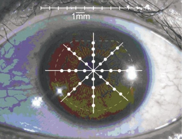
Imaging and measurement of the LASIK flaps were performed using RTVue OCT(Optovue Inc, Fremont, California, USA) system.We used the CAM-L scan pattern of the cornea anterior module to acquire scans of the cornea across a diameter of 8.0 mm for crossline analysis (Figure 1). The scan was centered on the vertex reflection, and 0°, 45°, 90°, 135° meridian OCT images were acquired and analyzed by the same ophthalmologist (Zhang J) 1wk after surgery, who was masked to the type of flap creation (Figure 2). Flap thickness was measured at 9 points in each meridian in 4 separate OCT images obtained for each eye (center, 1.0, 2.0 and 3.0 mm from the center and the peripheral zone of the flap). Center was defined as the range of ±0.5 mm from the flap vertex and peripheral zone, as the range within ±0.5 mm from the flap edge (i.e. approximately 3.75 to 4.25 mm from the center of the flap).
Figure 1. Example of frame-averaged horizontal line scan of corneal images.
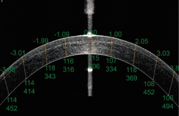
For each image, the upper numbers represent distances from the central cornea (mm). The lower numbers represent flap thickness and RSB thickness (mm), respectively.
Figure 2. Pupil image showing 0°, 45°, 90°, 135° meridional scans and flap thickness.
Statistical Analysis
Data were expressed as the mean±standard deviation (SD) and analyzed with SPSS software (version13.0, SPSS, Inc.). An independent samples t-test and one-way analysis of variance (ANOVA) were used to analyze data consistent with normal distribution. The Wilcoxon signed-rank test was applied to identify data not consistent with normal distribution. A P value less than 0.05 was considered statistically significant.
RESULTS
Baseline Demographics
Four hundred eyes of 200 patients were evaluated. Table 1 shows the baseline demographics of the patients. No significant differences were observed between the two groups (All P>0.05).
Table 1. Baseline patient characteristics.
| Parameters | Wavelight FS200 group (n=200) | Intralase FS60 group (n=200) | aP |
| Age (a) | 25.14±5.88 | 26.19±5.59 | 0.198 |
| SE (D) | -6.04±1.36 | -6.25±2.13 | 0.290 |
| CCT (µm) | 551.59±22.48 | 546.32±31.86 | 0.075 |
| Corneal curvature (D) | 43.89±1.03 | 43.65±1.32 | 0.170 |
| Intended flap (µm) | 110 | 110 | - |
CCT: Central corneal thickness; SE: Spherical equivalent; aIndependent-samples t-test.
x±s
Visual and Refractive Outcomes
The uncorrected visual acuity outcomes were 1.34±0.17 and 1.19±0.27 in Wavelight FS200 and Intralase group respectively 1wk after surgery (P=0.000) and the manifest refraction spherical equivalent were 0.00±0.48 and 0.11±0.80 diopters, respectively (P=0.104).
Corneal Flap Thickness
One week postoperatively, the mean flap thickness was 105.71±4.72 µm in WaveLight FS200 group and 109.78±11.42 µm in Intralase FS60 group (P=0.000; Figure 3). The mean central flap thickness was 105.39±4.50 µm in WaveLight FS200 group and 109.15±11.59 µm in Intralase FS60 group (P<0.001; Figure 4).
Figure 3. The mean flap thickness.
The mean flap thickness was 105.71±4.72 µm in WaveLight FS200 group and 109.78±11.42 µm in Intralase FS60 group.
Figure 4. The mean central flap thickness.
The mean central flap thickness was 105.39±4.50 µm in WaveLight FS200 group and 109.15±11.59 µm in Intralase FS60 group.
Corneal Flap Shape and Regularity
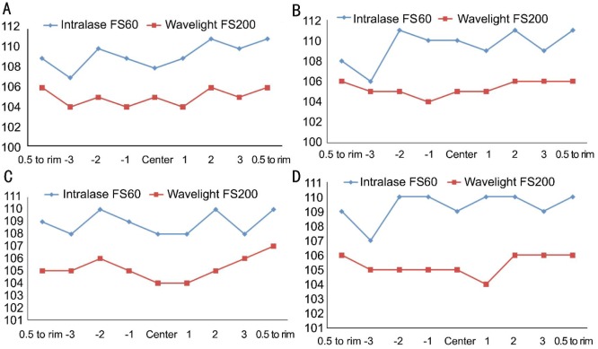
Table 2 shows the mean and SD of the flap thickness at each of the 36 locations measured in each eye for both groups. The maximum difference of the mean thickness at different measurement points was ±5 µm in WaveLight FS200 group and ±14 µm in Intralase FS60 group. Corneal flaps in both groups were uniform and regular, showing an almost planar configuration. Figure 5 provided the mean flap thickness in different meridians of the 36 points.
Table 2. Flap thickness at each measuring point.
| Locations | -Peri | -3.0 mm | -2.0 mm | -1.0 mm | Center | 1.0 mm | 2.0 mm | 3.0 mm | +Peri |
| Wavelight FS200 group | |||||||||
| 0° | 106±5 | 104±5 | 105±4 | 104±4 | 105±4 | 104±4 | 106±4 | 105±4 | 106±4 |
| 45° | 106±4 | 105±5 | 105±4 | 104±5 | 105±4 | 105±4 | 106±5 | 106±4 | 106±4 |
| 90° | 105±4 | 105±4 | 106±4 | 105±4 | 104±4 | 104±4 | 105±4 | 106±4 | 107±4 |
| 135° | 106±4 | 105±4 | 105±4 | 105±5 | 105±4 | 104±5 | 106±4 | 106±4 | 106±4 |
| Intralase FS60 group | |||||||||
| 0° | 109±10 | 107±11 | 110±14 | 109±11 | 108±11 | 109±11 | 111±11 | 110±11 | 111±10 |
| 45° | 108±9 | 106±11 | 111±11 | 110±11 | 110±11 | 109±11 | 111±11 | 109±11 | 111±10 |
| 90° | 109±9 | 108±10 | 110±12 | 109±12 | 108±11 | 108±10 | 110±11 | 108±11 | 110±10 |
| 135° | 109±10 | 107±11 | 110±11 | 110±11 | 109±11 | 110±11 | 110±11 | 109±10 | 110±9 |
±1.0 mm: Point 1.0 mm from flap vertex; ±2.0 mm: Point 2.0 mm from flap vertex; ±3.0 mm: Point 3.0 mm from flap vertex; Center: Range of ±0.5 mm from flap vertex; ±Peri: Range within 0.5 mm from the flap rim (approximately 3.75 to 4.25 mm from flap vertex).
x±s, µm
Figure 5. Comparison of flap thickness in the 0° (A), 45° (B), 90° (C) and 135° (D) meridian between Wavelight FS200 group and Intralase FS60 group.
Uniformity of Flap on Every Meridians
The mean flap thicknesses were 105.57±2.90, 105.71±2.65, 105.83±3.14 and 105.75±3.16 µm on the 0°, 45°, 90°, 135° meridians in WaveLight FS200 group (P=0.859), and 109.94±10.43, 109.37±10.26, 110.03±10.28 and 109.80±9.99 µm in Intralase FS60 group (P=0.923). There was no significant difference between the 2 groups.
Predictability of Flap-thickness
Table 3 shows the mean deviation between the measured and the intended flap thickness at each measuring point. The mean deviation in flap thickness was 5.18±3.71 µm in WaveLight FS200 group and 8.68±7.42 µm in Intralase FS60 group (P<0.001). The maximum deviation from the intended 110 mm thickness of 36 measurements was 6.2 µm in WaveLight FS200 group and 9.8 µm in Intralase FS60 group. WaveLight FS200 group has a better predictability than Intralase FS60 group.
Table 3. Mean deviations from intended flap thickness.
| Locations | -Peri | -3.0 mm | -2.0 mm | -1.0 mm | Center | 1.0 mm | 2.0 mm | 3.0 mm | +Peri |
| Wavelight FS200 group | |||||||||
| 0° | 5.0±3.5 | 5.8±4.1 | 5.1±3.7 | 5.9±3.8 | 5.0±3.6 | 5.9±4.1 | 4.6±3.3 | 4.8±3.4 | 4.7±3.4 |
| 45° | 4.8±3.2 | 5.3±4.2 | 4.9±3.5 | 6.0±4.0 | 5.4±3.9 | 5.4±4.0 | 5.1±3.5 | 4.7±3.3 | 4.4±2.8 |
| 90° | 4.9±3.5 | 5.6±3.8 | 4.9±3.5 | 5.5±3.5 | 5.4±3.6 | 6.1±4.0 | 4.7±3.4 | 4.6±2.9 | 4.0±3.2 |
| 135° | 4.8±3.3 | 5.6±4.0 | 5.0±3.8 | 5.9±3.8 | 5.1±3.5 | 6.2±4.4 | 4.7±3.8 | 4.8±3.3 | 4.4±3.0 |
| Intralase FS60 group | |||||||||
| 0° | 8.2±6.9 | 9.1±7.3 | 9.8±10.1 | 8.7±7.0 | 8.8±7.5 | 9.1±7.3 | 9.0±7.7 | 8.7±7.3 | 8.2±7.1 |
| 45° | 7.7±6.3 | 9.7±7.5 | 9.2±7.7 | 9.1±7.6 | 9.1±7.3 | 8.9±6.9 | 8.6±7.5 | 9.1±7.0 | 7.9±7.6 |
| 90° | 7.6±6.2 | 8.4±7.0 | 9.1±7.8 | 9.0±7.9 | 9.0±7.6 | 8.5±6.9 | 8.6±8.0 | 9.1±7.4 | 7.4±7.0 |
| 135° | 7.9±6.8 | 9.0±7.4 | 8.8±7.6 | 8.5±7.6 | 8.4±7.4 | 8.9±7.6 | 8.8±7.5 | 8.5±6.8 | 6.6±6.3 |
±1.0 mm: Point 1.0 mm from flap vertex; ±2.0 mm: Point 2.0 mm from flap vertex; ±3.0 mm: Point 3.0 mm from flap vertex; Center: Range of ±0.5 mm from flap vertex; ±Peri: Range within 0.5 mm from the flap rim (approximately 3.75 to 4.25 mm from flap vertex).
x±s, µm
Accuracy of Flap Thickness
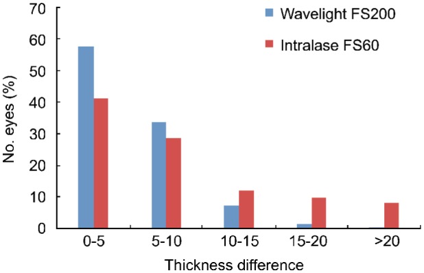
Figure 6 shows the distributions of the differences between the intended corneal flap thicknesses and the measured flap thicknesses in the Wavelight FS200 group and Intralase FS60 group. There are 4156 measurements (57.72%) on which the difference was less than 5 µm in the Wavelight FS200 group and 2965 measurements (41.18%) in Intralase FS60 group. But differences greater than 20 µm were observed in 15 measurements (0.2%) in the Wavelight FS200 group and 597 measurements (8.29%) in the Intralase FS60 group 1wk after surgery.
Figure 6. Distribution of the difference between the intended corneal flap thicknesses and the measured flap thicknesses in the Wavelight FS200 group and Intralase FS60 group.
DISCUSSION
LASIK has become the most popular approach in the world for the correction of refractive error due to many factors including the lack of postoperative pain, quick vision recovery, and the refractive accuracy of the procedure. The first step in LASIK is the preparation of the corneal flap, which is a critical and important step during the procedure. At present, a LASIK flap can be created with a mechanical microkeratome or femtosecond laser. Several studies[9]–[12] have compared femtosecond lasers and mechanical microkeratomes for corneal flap creation and found that the former may yield better safety, reproducibility, and predictability. A study in hyperopic patients showed significantly better refractive results with femtosecond laser flaps than with microkeratome flaps[13]. Another study showed that the incidence of epithelial ingrowth after femtosecond LASIK was less than microkeratome LASIK[14]. It is important to produce a uniform flap with a narrow SD from the intended thickness. A corneal flap, which is too thin, increases the incidence of flap related complications including a free, irregular, incomplete, buttonhole, or lacerated flap. A corneal flap, which is too thick, increases the likelihood of violating the minimum safe RSB thickness of 250 µm[15]–[16].
Although US pachymetry is considered the gold standard method for measuring CCT, it cannot be used to measure all regions of the cornea at once. Hence, several alternatives have been developed, including OCT. In this study, a new generation of Fourier-domain OCT (RTVue OCT, Optovue, Inc.) was used to compare the flap morphology. In this study, nominal flap thickness was set to 110 µm in both of the 2 femtosecond laser groups. The mean central flap thickness and the mean flap thickness in WaveLight FS200 group were thinner than in Intralase FS60 group. Several studies have evaluated femtosecond laser-created LASIK flaps. Zhou et al[12] enrolled 720 eyes of 360 patients to measure the flaps created by the Intralase FS60 femtosecond and found that Intralase flaps with an intended thickness of 110 µm were actually a mean of 110.5±2.9 µm. Zhang et al[17] enrolled 408 eyes of 204 patients to measure the flaps created by the Intralase FS60 femtosecond laser using the RTVue OCT and found that Intralase flaps with an intended thickness of 110 µm were actually a mean of 109.34±7.57 µm. Our results are consistent with findings in the above studies. In our study the mean flap thickness was 105.71±4.72 µm in Wavelight FS200 group and 109.78±11.42 µm in Intralase FS60 group. The mean central flap thickness was 105.39±4.50 µm in Wavelight FS200 group and 109.15 ±11.59 µm in Intralase FS60 group. This difference may be related to the calibration of the different femtosecond laser systems. It may also be due to the difference of energy or frequency of laser we used. The mean thickness of the different research may be related to the kind of OCT used for measurement, and different number of eyes enrolled.
Previous studies found that flaps created by femtosecond laser had uniform thickness and resulted in planar shaped flaps compared with microkeratome-created flaps. A uniform and regular flap may contribute to more predictable refractive and wavefront outcomes[18]–[19]. Zhang et al[17] found that the mean deviation of flap created by Intralase FS60 between the measured and the intended thickness was 6.59 µm. Our results are consistent with findings in the above studies. The deviation of less than 5 µm in the Wavelight FS200 group was 57.72% and 41.18% in Intralase FS60 group. The deviation of more than 20 µm was 0.2% measurements in Wavelight FS200 group and 8.29% measurements in Itralase FS60 group.
In summary, the flaps made with the Wavelight FS200 femtosecond laser were thinner than those created by the Intralase FS60. The Wavelight FS200 femtosecond laser group has more predictability and uniformity of flap creation. Further studies are needed to determine whether the thinner and regular corneal flap contributes to improving postoperative biomechanical reaction and reducing higher-order aberrations. In recent years, many kinds of femtosecond laser as Intralase FS150, VisuMax, Femto LDV and Wavelight FS200 were used to create flaps of LASIK and more research with large sample size needed to be done to analyze the regularity, uniformity and accuracy of the different types of flaps. This is only a short-term study of corneal flap thickness between the 2 femtosecond lasers. Long-term outcomes needed to be done to explore the consequence of the different corneal flap created by the 2 femtosecond lasers.
Acknowledgments
Conflicts of Interest: Liu Q, None; Zhou YH, None; Zhang J, None; Zheng Y, None; Zhai CB, None; Liu J, None.
REFERENCES
- 1.Sandoval HP, de Castro LE, Vroman DT, Solomon KD. Refractive surgery survey 2004. J Cataract Refract Surg. 2005;31(1):221–233. doi: 10.1016/j.jcrs.2004.08.047. [DOI] [PubMed] [Google Scholar]
- 2.Sugar A, Rapuano CJ, Culbertson WW, Huang D, Varley GA, Agapitos PJ, de Luise VP, Koch DD. Laser in situ keratomileusis for myopia and astigmatism: safety and efficacy: a report by the American Academy of Ophthalmology. Ophthalmology. 2002;109(1):175–187. doi: 10.1016/s0161-6420(01)00966-6. [DOI] [PubMed] [Google Scholar]
- 3.Zhou Y, Tian L, Wang N, Dougherty PJ. Anterior segment optical coherence tomography measurement of LASIK Flaps: femtosecond laser vs microkeratome. J Refract Surg. 2011;27(6):408–416. doi: 10.3928/1081597X-20101029-01. [DOI] [PubMed] [Google Scholar]
- 4.Reggiani-Mello G, Krueger RR. Comparison of commercially avail-able femtosecond lasers in refractive surgery. Expert Rev Opthalmol. 2011;6(1):55–65. [Google Scholar]
- 5.Binder PS, Trattler WB. Evaluation of a risk factor scoring system for corneal ectasia after LASIK in eyes with normal topography. J Refract Surg. 2010;26(4):241–250. doi: 10.3928/1081597X-20100212-02. [DOI] [PubMed] [Google Scholar]
- 6.Reinstein DZ, Archer TJ, Gobbe M. Comparison of residual stromal bed thickness measurement among very high-frequency digital ultrasound, intraoperative handheld ultrasound, and optical coherence tomography. J Refract Surg. 2012;28(1):42–47. doi: 10.3928/1081597X-20110825-02. [DOI] [PubMed] [Google Scholar]
- 7.Dawson DG, Randleman JB, Grossniklaus HE, O'Brien TP, Dubovy SR, Schmack I, Stulting RD, Edelhauser HF. Corneal ectasia after excimer laser keratorefractive surgery: histopathology, ultrastructure, and pathophysiology. Ophthalmology. 2008;115(12):2181–2191.e1. doi: 10.1016/j.ophtha.2008.06.008. [DOI] [PubMed] [Google Scholar]
- 8.Ou RJ, Shaw EL, Glasgow BJ. Keratectasia after laser in situ keratomileusis (LASIK): evaluation of the calculated residual stromal bed thickness. Am J Ophthalmol. 2002;134(5):771–773. doi: 10.1016/s0002-9394(02)01656-2. [DOI] [PubMed] [Google Scholar]
- 9.Patel SV, Maguire LJ, McLaren JW, Hodge DO, Bourne WM. Femtosecond laser versus mechanical microkeratome for LASIK. Ophthalmology. 2007;114(8):1482–1490. doi: 10.1016/j.ophtha.2006.10.057. [DOI] [PubMed] [Google Scholar]
- 10.Lim T, Yang S, Kim M, Tchah H. Comparison of the IntraLase femtosecond laser and mechanical microkeratome for laser in situ keratomileusis. Am J Ophthalmol. 2006;141(5):833–839. doi: 10.1016/j.ajo.2005.12.032. [DOI] [PubMed] [Google Scholar]
- 11.Pietilä J, Huhtala A, Jääskeläinen M, Jylli J, Mäkinen P, Uusitalo H. LASIK flap creation with the Ziemer femtosecond laser in 787 consecutive eyes. J Refract Surg. 2010;26(1):7–16. doi: 10.3928/1081597X-20101215-02. [DOI] [PubMed] [Google Scholar]
- 12.Zhou Y, Zhang J, Tian L, Zhai C. Comparison of the Ziemer FEMTO LDV femtosecond laser and Moria M2 mechanical microkeratome. J Refract Surg. 2012;28(3):189–194. doi: 10.3928/1081597X-20120208-01. [DOI] [PubMed] [Google Scholar]
- 13.Gil-Cazorla R, Teus MA, de Benito-Llopis L, Mikropoulos DG. Femtosecond laser vs mechanical microkeratome for hyperopic laser in situ keratomileusis. Am J Ophthalmol. 2011;152(1):16–21.e2. doi: 10.1016/j.ajo.2011.01.009. [DOI] [PubMed] [Google Scholar]
- 14.Kamburoglu G, Ertan A. Epithelial ingrowth after femtosecond laser-assisted in situ keratomileusis. Cornea. 2008;27(10):1122–1125. doi: 10.1097/ICO.0b013e3181731439. [DOI] [PubMed] [Google Scholar]
- 15.Wang Z, Chen J, Yang B. Posterior corneal surface topographic changes after laser in situ keratomileusis are related to residual corneal bed thickness. Ophthalmology. 1999;106(2):406–409. doi: 10.1016/S0161-6420(99)90083-0. [DOI] [PubMed] [Google Scholar]
- 16.Randleman JB, Russell B, Ward MA, Thompson KP, Stulting RD. Risk factors and prognosis for corneal ectasia after LASIK. Ophthalmology. 2003;110(2):267–275. doi: 10.1016/S0161-6420(02)01727-X. [DOI] [PubMed] [Google Scholar]
- 17.Zhang J, Zhou Y, Zhai C, Tian L. Comparison of 2 femtosecond lasers for laser in situ keratomileusis flap creation. J Cataract Refract Surg. 2013;39(6):922–927. doi: 10.1016/j.jcrs.2013.01.042. [DOI] [PubMed] [Google Scholar]
- 18.Reinstein DZ, Archer TJ, Gobbe M. LASIK flap thickness profile and reproducibility of the standard vs zero compression Hansatome microkeratomes: three-dimensional display with Artemis VHF digital ultrasound. J Refract Surg. 2011;27(6):417–426. doi: 10.3928/1081597X-20101110-01. [DOI] [PubMed] [Google Scholar]
- 19.Tran DB, Sarayba MA, Bor Z, Garufis C, Dun YJ, Soltes CR, Juhasz T, Kurtz RM. Randomized prospective clinical study comparing induced aberrations with IntraLase and Hansatome flap creation in fellow eyes; potential impact on wavefront-guided laser in situ keratomileusis. J Cataract Refract Surg. 2005;31(1):97–105. doi: 10.1016/j.jcrs.2004.10.037. [DOI] [PubMed] [Google Scholar]


