Abstract
The root-mean-square (rms) output voltage of the NIST Josephson arbitrary waveform synthesizer (JAWS) has been doubled from 1 V to a record 2 V by combining two new 1 V chips on a cryocooler. This higher voltage will improve calibrations of ac thermal voltage converters and precision voltage measurements that require state-of-the-art quantum accuracy, stability, and signal-to-noise ratio. We achieved this increase in output voltage by using four on-chip Wilkinson dividers and eight inner-outer dc blocks, which enable biasing of eight Josephson junction (JJ) arrays with high-speed inputs from only four high-speed pulse generator channels. This approach halves the number of pulse generator channels required in future JAWS systems. We also implemented on-chip superconducting interconnects between JJ arrays, which reduces systematic errors and enables a new modular chip package. Finally, we demonstrate a new technique for measuring and visualizing the operating current range that reduces the measurement time by almost two orders of magnitude and reveals the relationship between distortion in the output spectrum and output pulse sequence errors.
Keywords: Digital-analog conversion, Josephson junction arrays, Measurement standards, Signal synthesis, Superconducting integrated circuits, Voltage measurement
I. Introduction
Josephson voltage standards are important metrological tools that are based on the voltage pulses with quantized areas that are associated with flux quanta traversing Josephson junctions (JJs). Arrays of series-connected JJs are required to produce calculable voltages with sufficient magnitude for practical measurements and calibration of commercial instruments [1]. The newest voltage standards that are optimized for dc voltage measurements, called programmable Josephson voltage standards (PJVSs) [2], have had great success generating large output voltages by biasing the JJs with 16 GHz to 20 GHz (up to +/− 17 V [3]) or 70 GHz (up to +/− 20 V [4]) microwave signals. A single microwave signal is input to the superconducting integrated circuit where it is divided to bias 32 or 64 different JJ arrays [2]–[4]. This on-chip division of the microwave signal is accomplished using multiple stages of microwave dividers. Dividers with modest bandwidth are sufficient because PJVSs use a single-frequency bias.
The Josephson arbitrary waveform synthesizer (JAWS) [5], which is also known as the ac Josephson voltage standard (ACJVS), does not use a single-frequency microwave bias. Instead, the JJ arrays are driven by current pulses with a repetition rate of about 15×109 pulses/s (e.g. [6] or [7]). A time-dependent output voltage with exactly calculable voltage and harmonic spectrum is created by ensuring that every JJ generates a known number of quantized voltage output pulses, usually one pulse, for every bias pulse of the high-speed input [8].
Since the long patterns of bias pulses that are used to synthesize low frequency (< 1 MHz) waveforms have Fourier components spread over a wide bandwidth, the high-speed connection between the JJ arrays and the pulse generator channels must also have a wide bandwidth so as to ensure that the pulse waveform bias is not distorted. In the past, this broadband requirement was achieved by directly connecting each JJ array to a single dedicated channel of a high-speed pulse generator, with minimal off-chip and on-chip microwave components. This approach of using one channel per array has been used in all previous JAWS systems for the past 20 years, including the most recent systems with an rms output voltage of 1 V that used one chip with four arrays [9]-[10] and four chips with eight arrays [11].
Each high-speed channel also requires a coaxial connection between the room-temperature pulse generator output channel and the cryogenic on-chip coplanar waveguide (CPW) launch. While it is technically possible to achieve a higher output voltage using additional high-speed input lines to bias additional arrays, the required electronics and cryogenic engineering quickly become complex and cost prohibitive.
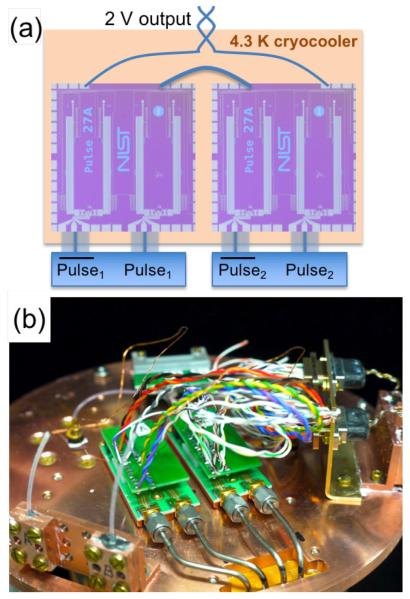
In this paper, we double the rms output voltage of the JAWS system to 2 V by following the approach used with PJVS systems and implementing, for the first time in a pulse-driven system, broadband on-chip Wilkinson dividers and inner-outer dc blocks to distribute pulses from single high-speed input lines to pairs of JJ arrays. This 2 V JAWS system uses two chips mounted on a cryocooler at 4.3 K with a total of eight JJ arrays driven by four high-speed pulse channels, as shown in Fig. 1. The eight-array system has a collective operating current range of 1.6 mA at 2 V and 1 kHz. For comparison, the previous NIST 1 V system had an operating current range of 2.1 mA [10], which shows that the new on-chip microwave components cause only a small reduction in the operating current range. We have also implemented on-chip superconducting interconnects between the four arrays of each chip, simplified the cryogenic packaging and low-speed bias interconnects, and introduced a new, faster method for measuring and visualizing the distortion-free operating current range of the JAWS system.
Fig. 1.
(a) Simplified schematic, including chip photos, and (b) photograph of the NIST 2 V JAWS cryostat cold head showing the two 1 V JAWS packages and associated interconnects. Each package has two high-speed coaxial biases.
II. Advances in On-Chip Circuits
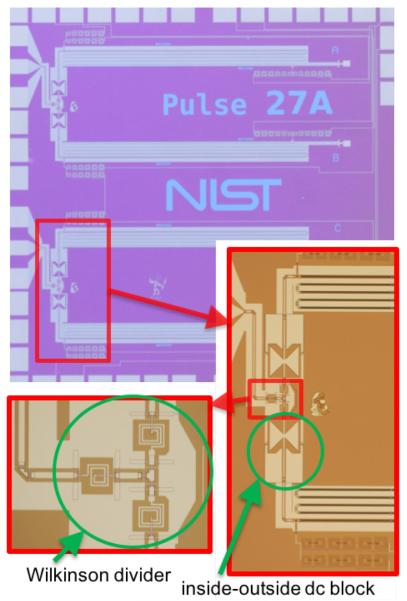
The NIST 1 V JAWS chip with Wilkinson dividers is shown in Fig. 2. The Wilkinson dividers used in the NIST PJVS system have a designed center frequency of 20 GHz and −10 dB isolation bandwidth of around 15 GHz [2], [12]. In comparison, the Wilkinson dividers for the JAWS system have a higher designed center frequency of 26 GHz and the same approximate 15 GHz isolation bandwidth. The large bandwidth and high center frequency are essential for the JAWS circuit because the design maximizes the input pulse power that passes through the divider, which minimizes the pulse pattern dependent variations in the high-frequency bias that reaches the JJ arrays. Also, the Wilkinson dividers evenly divide out-of-band signals because the output loads, namely, the two JJ arrays, are symmetric to within the fabrication tolerances. The isolation between arrays and the power coupled into the arrays both decrease outside of the designed bandwidth [13].
Fig. 2.
Photograph of 1 V JAWS chip, with enlargement on two inner-outer dc blocks and a Wilkinson divider. The two high-speed pulse inputs are on the left side of the chip; the low-frequency inputs and outputs are on the other sides of the chip.
As in PJVS circuits, adding the JJ array voltages in series requires that the arrays are electrically floating relative to each other. Previous 1 V JAWS chips used room-temperature inner-outer dc blocks to isolate the JJ arrays [9]–[11]. This approach is incompatible with on-chip Wilkinson splitters because the arrays must be isolated after the splitter. In the PJVS circuits, this is accomplished using an on-chip inner dc block on both the input of each pair of JJ arrays (immediately after a Wilkinson divider) and the output of each JJ array (immediately before the resistive microwave termination).
For the JAWS circuit, we isolated the JJ arrays by fabricating inner-outer dc-blocks between the output of the Wilkinson divider and the JJ array (Fig. 2). These blocks replace the room-temperature blocks used in the earlier JAWS systems. They also provide significantly improved isolation, with respective inner/outer blocking capacitance of 6.5 pF and 14 pF, respectively, for the new on-chip blocking capacitors versus 500 nF and 5 nF for the room-temperature dc block component. These parameters effectively result in on-chip high-pass filtering with a 3 dB point of 380 MHz. This filtering has the potential to affect the shape of some pulses; however, the pulses are fast enough that nearly all of the pulse power is above 500 MHz. Thus, the on-chip blocks should minimally affect the pulses. As in earlier JAWS systems, the highest output voltages require that each JJ array also be biased with a floating low-frequency current to compensate for the low-frequency signal that is removed with the high-pass filter [6].
We have modified the JJ array design from that in the previous 1 V JAWS design [9], [10]. Instead of 6400 stacks of two self-shunted JJs per array (a total of 12 800 JJs per array), we now use 4270 stacks of three self-shunted JJs per array (a total of 12 810 JJs per array). These JJ arrays have a minimum critical current Ic between 10.5 mA and 12.0 mA at 4.2 K and the impedance-tapered CPWs are terminated with 21 Ω resistors. The individual JJs have an area of 56 μm2 and an average junction resistance of 4 mΩ. A detailed description of the fabrication is presented elsewhere [14]–[16].
As a final improvement to the on-chip circuit, we replaced with on-chip superconducting interconnects all three of the off-chip hand-soldered copper jumper wires that were used previously for connecting in series the voltage outputs of the four arrays. As in [6], [9], [10], [17], it is necessary to have on-chip spiral inductors near the connection between the JJ array and the interconnect (see Fig. 2). This series of inductors, with a total inductance of around 60 nH, acts as a low-pass filter and ensures that the majority of the high-frequency current bias signal remains to bias the JJ array, while transmitting the lower frequency (< 100 MHz) output voltage. Compared to the previous copper wires, the superconducting interconnects reduce the inductance and resistance of the connection. This reduces sources of error associated with undesirable currents in the voltage leads, which is important because parasitic capacitances, leakage resistances, and other non-ideal circuit components typically produce small ac currents that can flow through the voltage leads [18]–[20].
III. 2 V JAWS System
We integrated two of the new 1 V chip packages onto a cryocooler (Fig. 1) and connected them in series to generate quantum-accurate waveforms with an rms magnitude of 2 V. A single chip is mounted in a cryogenic package as described in [9], [10]. As a consequence of the above mentioned new on-chip microwave components and superconducting interconnects, we have significantly improved the modularity of the cryopackage and simplified the printed circuit board (PCB). The new chip and surrounding package are shown in Fig. 3. In comparison to Refs. [9], [10], implementation of the Wilkinson dividers has halved the number of high-speed connections required to bias the four on-chip arrays so that only two SMA connectors are required per 1 V JAWS package.
Fig. 3.
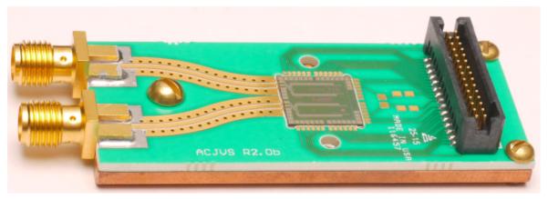
Photograph of the new 1 V JAWS package. The four on-chip JJ arrays are biased through two SMA connectors and corresponding CPW lines. All low-frequency connections are made through the compact 30-pin connector
We use the rest of the PCB to improve the modularity of the system by adding a compact 30-pin cryogenic-compatible connector. The low-frequency signal leads, specifically the current biases for each array and three identical pairs of leads for the total JAWS output voltage, are all wire bonded from the chip to the PCB. Traces on the PCB take these signals to the connector. Finally, twisted pairs of wires from room temperature are attached to another small interposer PCB with the opposite gender connector (observable in Fig. 1b), creating a connection to room temperature for all of the low frequency biases and the voltage outputs. This connector has been tested in the NIST Programmable Josephson Voltage Standard (PVJS) packages for the past two years and does not decrease the PJVS system leakage resistance [21]. It also does not significantly increase the stray admittance above that already present in the twisted pairs of wires.
To produce the 2 V rms output voltage with this JAWS system, we mounted two of these packages on a cryocooler and connected the output voltage leads of the two packages in series (Fig. 1). Liquid helium is expensive and can be difficult or impossible to obtain for some laboratories, thus generating 2 V on a cryocooler is an important step towards creating a user-friendly JAWS system. Details of the cryocooled system are described in [22]–[24] and will be discussed in more detail elsewhere. The two chips are connected in series at cryogenic temperatures with a copper jumper wire between the two interposer PCBs. The cryocooler has a base temperature of 2.8 K, but is temperature controlled at 4.3 K.
The 2 V JAWS system uses custom, large-memory pulse generators to generate large amplitude current pulses that drive the JJ arrays at a rate of 14.4×10⁹ pulses/s [6]. The output pulse power for each pulse generator channel was doubled in order to properly bias the two arrays connected to each Wilkinson divider. Each pair of pulse generator outputs has six parameters that are used to tune the high-frequency bias: the magnitude and phase of one single-frequency generator per output, the magnitude of a stream of bits, and the relative phase between the bits and the low-frequency compensation. We also individually control the amplitude of the low-frequency current compensation bias for each array, resulting in a total of ten tuning parameters per chip, and a dither current that is used to measure the operating current range.
IV. 2 V JAWS Operating Current Range
We synthesized a 1 kHz sine wave with an rms magnitude of 2 V and determined that the system had an operating current range of 1.6 mA. We measured the operating current range using a faster version of the standard approach [6], [9], [25]–[28] of determining the range of dc dither current that does not change the total harmonic distortion (THD), i.e. the “flat spot.” The THD is measured using a sensitive digitizer by summing the power in the first twenty harmonics of the synthesized sine wave. Increasing the measurement speed is particularly important for computer-controlled optimization of system parameters and for characterizing synthesized waveforms at frequencies above 100 kHz. Computer-controlled optimization depends on quickly measuring a large number of parameter configurations.
A measurement of an “operating range” is intended to show that a JAWS system is quantum-accurate and that it is stable. That is, it quantifies whether every JJ can create one output voltage pulse per input current pulse despite changes in the electrical or physical environments (for example, changes in the output load or unintentional changes in the bias that reaches the JJ arrays). The standard technique used while developing the JAWS system has been to measure the “operating current range,” which is the range of dc dither current that can be applied to the JJ arrays without creating an error where at least one input pulse in the pattern causes at least one JJ to produce the wrong number of output pulses. If such an error occurs, then the waveform is no longer quantum-accurate. Detailed comparisons between different Josephson voltage standard circuits and systems typically examine in more detail the effect of changing other system parameters [29]–[32].
The dc dither current is particularly relevant for characterizing a JAWS system because small stray bias currents can be introduced by changes in the system configuration (grounding, different devices under test, etc.). More specifically, the JAWS system must be able to handle the transition from the measurement device used to determine the operating margins, usually a sensitive digitizer, to the device under test, such as a thermal converter with a lower input impedance. These connections can induce dc and ac currents in the JJ arrays that must not introduce errors which would result in an output waveform that is not quantum-accurate.
The dc dither current affects the high-frequency pulse response because of the large nonlinearity of the JJs. At sufficiently large positive and negative dc current, some input current pulses will generate an extra output pulse or not generate any output pulse. These extra or absent output pulses will cause the output voltage to deviate from the desired output waveform and will also create distortion.
The standard technique for determining the operating current range involves measuring the THD as a function of offset current (see Fig. 4b, for example) instead of directly measuring extra or absent output pulses. The combination of the 70 ps pulse length and a magnitude less than 100 μV for individual JJ pulses makes directly measuring missing or extra pulses unfeasible. Instead, we use a low-frequency digitizer (the NI-59221 with a maximum sample rate of 15 MS/s) to sensitively compare the desired output waveform to the measured waveform. This technique focuses on detecting the distortion created by the extra or absent output pulses.
Fig. 4.
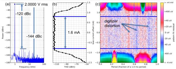
Digitally sampled spectral measurement (a) showing a low distortion JAWS output voltage with an rms magnitude of 2 V. The digitizer was set to its 10 V range with a 1 MΩ input impedance and a 1 MS/s sampling rate. There is a +/− 0.75 mA dither current applied during the 40 ms of data used to generate the FFT, that is, between the blue lines in (b) and (c) that indicate the JAWS operating current range. In (b) we plot THD versus dither offset current showing the 1.6 mA operating current range. In (c) we plot the same data as in (b) so as to show the voltage residuals of a fit to a sinusoid (color) versus dither offset current (y-axis) and waveform period (x-axis) which highlights the pulse sequences at 0.25, 0.6, and 0.9 periods that limit the operating current range.
The sensitivity of the technique is limited by the nonlinearities and noise floor of the digitizer. In particular, the nonlinearities of the digitizer amplifier and analog-to-digital convertor create harmonics in the measured spectrum. These measurement artifacts depend on both the magnitude of the output voltage and the digitizer calibration. When measuring a sinusoidal output voltage with an rms magnitude of 1 V, the inherent digitizer nonlinearities typically produce harmonics that are −118 dBc (dB below the carrier/fundamental tone), whereas the accompanying noise floor is −138 dBc (see [9] for typical spectra). For comparison, a fast Fourier transform (FFT) of the designed pulse pattern shows that the JAWS output harmonics should be on the order of −180 dBc at frequencies below 2 MHz [33][34]. This is 40 dB below the noise floor of the digitizer and 60 dB below the harmonics created by the digitizer nonlinearities.
Since the digitizer introduces a large background compared to the signal at the harmonic frequencies, it is not possible to determine whether the system is operating correctly just by looking at a single measurement of the THD. Instead, we first confirm that the magnitude of the measured THD is consistent with the expected digitizer background. Then, we vary a control parameter, in this case the dc dither current, and determine the range of parameter settings over which the THD does not increase. The THD starts to increase when there are enough extra or missing pulses that the resulting distortion is visible despite the digitizer background. Therefore, the measured operating current range is only an upper limit, and improvements in the measurement signal-to-noise would likely result in a decrease in the measured operating range.
We used this technique to determine the operating current range of the 2 V JAWS system and we have increased the measurement speed relative to previous measurements [9], [10]. The applied dither current is a 7 Hz triangle wave with 3 mA peak-to-peak amplitude. Since the triangle wave frequency is much less than the pattern frequency, the offset current is approximately constant during each pattern period. We can therefore calculate the THD of each period of the pattern and plot the THD, that is, the sum of the power in the first twenty harmonics, as a function of the average dc-offset current during the period (Fig. 4b).
From Fig. 4, we observe a range of 1.6 mA over which the THD is independent of the bias current. Beyond this range the THD begins to increase as extra or absent pulses create measurable distortion. We confirm this operating current range by plotting an FFT of the measured output waveform over the full 1.6 mA operating current range (Fig. 4a, the FFT is taken of the data between the blue lines in Fig. 4b/c). We observe harmonics with a maximum magnitude of −144 dBm (−120 dBc), and noise of −168 dBm (−144 dBc), consistent with the expected digitizer performance.
This measurement of the operating current range is faster than previous methods, in this case with approximately seven measurements per second, with a signal-to-noise that is controlled by the required offset current resolution and the measurement time. This is an improvement of almost two orders of magnitude over early measurements that used 10 s per measurement [9], [10]. The trade-off between speed and precision is particularly important when trying to implement algorithmic optimization of the drive parameters to maximize the operating current range. There are ten, highly coupled, bias parameters per chip; thus, the optimization problem requires a large number of iterations in order to converge. Being able to quickly measure the effect of changing the tuning parameters increases the feasibility of computer-controlled optimization [28].
We also individually measured the two chips while immersed in liquid helium and observed respective operating current ranges of 2.8 mA and 2.6 mA while synthesizing 1 kHz sine waves with rms magnitudes of 1 V. We typically observe larger operating current ranges when operating JAWS circuits in liquid helium than we do when operating them on a cryocooler. We suppose that the larger ranges result from the larger heat capacity of the liquid helium reservoir enabling better thermal stability of the JAWS circuit [22]–[24].
V. Visualization of JAWS Operation
We have developed a new way of visualizing the operating current range that combines the increased measurement speed described earlier with an emphasis on the connection between output waveform distortion and input pulse sequences that generate incorrect numbers of pulses, that is, sequences that result in extra or missing pulses (Fig. 4c). In the future, improving our understanding of difficult pulse sequences may lead to new methods for optimizing bias parameters or to changes in the delta-sigma algorithm [34] in order to avoid these sequences. This approach will also be useful when evaluating the performance of the system with non-sinusoidal waveforms. Instead of concentrating on THD, we would directly look at deviations from the calculated waveform.
Using the same digitized waveform that we used to calculate the operating current margins in the previous section, we plot the relationship in the time domain between the input pulse pattern and the output distortion as a function of the offset current. In Fig. 4c we make a logarithmic density plot of the residuals (color) of a fit to a 1 kHz sine wave as a function of time in units of pattern period (x-axis) and offset current (y-axis). The sine wave fit was accomplished by using the 1 kHz component of an FFT of the data. In this density plot, distortion is directly observable in the residuals. The operating current range is the vertical region where each horizontal slice of residuals has a small magnitude (light red, white, or light blue noise in the density plot). This density plot is similar to analog oscilloscope measurements of the swept current-voltage characteristics of the JJ arrays [10], but with improved sampling rate, sensitivity, and programmability.
As with analog oscilloscope visualizations [10], this plot visually highlights the specific input pulse sequences that do not produce the correct output voltage pulses, observed at the upper and lower edges of Fig. 4c. In this case, the sequence of pulses near 0.25 fraction of a period is no longer correctly produced when under a negative dc offset current of −0.8 mA, while the pulse sequences at 0.6 and 0.9 fractions of a periods are incorrect under a positive dc offset current of 0.8 mA. The maximum current range between these boundaries determines the total JAWS operating current range of 1.6 mA. As expected, this is the same value as determined from measuring the THD. We also observe the distortion introduced by the nonlinearities in the digitizer, that is, the noisy vertical red or blue striped bands that are independent of offset current. This is exactly the same distortion that produced the harmonics in the spectrum of Fig. 4a with a maximum magnitude of −120 dBc.
In practice, if a particular finite pulse sequence limits the operating current range (for example, the vertical spurs of distortion observed at 0.6 and 0.9 fractions of a period and −0.8 mA offset), it is often possible to reduce the distortion and increase the operating range by tuning the pulse generator bias parameters. It is worth noting that even an error in a very short pulse sequence (a narrow region of distortion) is unacceptable for accurate JAWS operation. In that region, the JJ arrays are no longer generating the correct number of output pulses per input current pulse, and therefore the exact output voltage is not calculable. Even if the distortion appears stable and relatively insensitive to the dc current offset, the output waveform is still not quantum-accurate.
VI. Conclusion
In conclusion, we have shown that on-chip superconducting Wilkinson dividers combined with on-chip inner-outer dc blocks can be used to drive a pair of JJ arrays with a single pulse generator output channel. This is analogous to the way that the PJVS uses Wilkinson dividers to split a single-frequency microwave signal between multiple arrays. For each JAWS chip, we sum the voltage of the four JJ arrays at low-frequency using on-chip superconducting interconnects. These improvements enabled the development of a simplified cryopackage and interface PCBs for making electrical connections to the on-chip superconducting circuits.
We verified the performance of these microwave structures by creating a 2 V JAWS system operating on a cryocooler at 4.3 K and we demonstrated a 1.6 mA operating current range. We also introduced a new way of visualizing the operating range that more critically optimizes and reveals the JAWS performance. These measurements demonstrated that our improvements did not degrade the system performance, and, in fact, allowed us to double the maximum output voltage of the JAWS system with an acceptable 0.5 mA reduction in the operating current margins.
We anticipate that this approach of increasing the JAWS output voltage by increasing the complexity of the on-chip microwave circuits will continue to enable higher voltages in the future by using multiple stages of Wilkinson divider circuits in the high-speed bias path. This ability to generate larger, distortion-free, arbitrary waveforms with quantum-accurate voltage will enable new applications for high precision AC calibrations using the JAWS system.
ACKNOWLEDGMENT
We thank Steve Waltman for development of the custom pulse generators and bias electronics, Mike Elsbury and Zoya Popović for developing microwave designs, the Boulder Microfabrication Facility for facilitating chip fabrication, and Dan Schmidt for photographic assistance.
Biography
Nathan E. Flowers-Jacobs was born in Urbana, IL on June 15, 1979. He received a B.S. degree in physics from the California Institute of Technology, Pasadena, CA in 2001. He worked at MIT Lincoln Laboratory modeling radar cross sections for two years before entering graduate school at JILA and the University of Colorado-Boulder where he received a Ph.D. in physics in 2010 for his work on a quantum-limited detector of nanomechanical motion based on electron tunneling across an atomic point contact. From 2010-2014 he was a Postdoctoral Associate at Yale University working on nanomechanical displacement measurements at the quantum limit using optical cavities.
In 2014 he joined the Quantum Voltage Project at the National Institute of Standards and Technology (NIST), Boulder, CO, and has been working on development, characterization, and applications of the Josephson Arbitrary Waveform Synthesizer (JAWS), an ac Josephson voltage standard based on pulse-biased arrays of Josephson junctions.

Anna E. Fox received her Ph.D. in Electrical Engineering from Drexel University in 2009.
From 2009 to 2010 Dr. Fox was a National Research Council Postdoctoral researcher in the Optoelectronics Division at the National Institute of Standards and Technology in Boulder, CO where she worked fabricating superconducting transition-edge sensors for use at optical wavelengths. She continued her work in transition-edge sensor fabrication in the NIST Quantum Sensors Project where she fabricated arrays of TES bolometers for cosmic microwave background detection.
Dr. Fox has been with the NIST Quantum Voltage Project since 2013 pursuing the design and fabrication of voltage standard devices such as the Programmable Josephson Voltage Standard and the AC Josephson Voltage Standard.
Paul D. Dresselhaus was born in Arlington, MA, on January 5, 1963. He received the B.S. degree in physics and electrical engineering from the Massachusetts Institute of Technology, Cambridge, in 1985 and the Ph.D. degree in applied physics from Yale University, New Haven, CT, in 1991.
In 1999, he joined the Quantum Voltage Project, the National Institute of Standards and Technology, Boulder, CO, where he has been developing novel superconducting circuits and broadband bias electronics for precision voltage waveform synthesis and programmable voltage standard systems. He has been the Project Leader of the Quantum Voltage Project at NIST since October 2015. He was with Northrop Grumman for three years, where he designed and tested numerous gigahertz-speed superconductive circuits, including code generators and analog-to-digital converters. He also upgraded the simulation and layout capabilities at Northrop Grumman to be among the world’s best. He has also been a Postdoctoral Assistant with State University of New York, Stony Brook, where he worked on the nanolithographic fabrication and study of Nb–AlOx–Nb junctions for single-electron and SFQ applications, single-electron transistors and arrays in Al–AlOx tunnel junctions, and the properties of ultrasmall Josephson junctions.
He received two U.S. Department of Commerce Gold Medals for Distinguished Achievement and the 2006 IEEE Council on Superconductivity Van Duzer Prize.

Robert E. Schwall (M’91–SM’98) received his B.S. in physics from St. Mary’s University of Texas in 1968 and his M.S. and PhD in Applied Physics from Stanford University in 1969 and 1972 respectively.
He worked for IBM from 1984 to 1993 where he developed and patented a quench protection system for superconducting MRI magnets which was utilized worldwide for over 20 years. At the IBM T.J. Watson Research Lab. he served as manager of the Optical Systems group and also led a project addressing the packaging and cooling of CMOS circuits operating at cryogenic temperatures. From 1993 to 2003 he held a number of positions at American Superconductor Corp. in Westborough MA. There he was Vice President of Engineering, leading the development of the high temperature superconductors BSCCO and thin film YBCO. He is currently at the National Institute of Standards and Technology (NIST) working on programs in voltage standards, ultra-low field MRI, and cryogen-free systems incorporating superconducting sensors.
Dr. Schwall is a Fellow of the American Physical Society and a Senior Member of the IEEE Council on Superconductivity. He is author of over 70 publications and holder of 9 patents in the field of superconductivity.

Samuel P. Benz (M’01-SM’01-F’10) was born in Dubuque, IA, on December 4, 1962. He received the B.A. degree (summa cum laude) in physics and math from Luther College, Decorah, IA, in 1985 and the M.A. and Ph.D. degrees in physics from Harvard University, Cambridge, MA, in 1987 and 1990, respectively. He was awarded an R.J. McElroy Fellowship (1985–1988) to work toward the Ph.D. degree.
In 1990, he joined the National Institute of Standards and Technology (NIST), Boulder, CO, as a NIST/NRC Postdoctoral Fellow and became a permanent Staff Member in January 1992. He has been the Project Leader of the Quantum Voltage Project at NIST since October 1999, and Group Leader of the Superconductive Electronics Group since 2015. He has worked on a broad range of topics within the field of superconducting electronics, including Josephson junction array oscillators, single flux quantum logic, ac and dc Josephson voltage standards, Josephson waveform synthesis, and noise thermometry. He has over 220 publications and is the holder of three patents in the field of superconducting electronics.
Dr. Benz is a Fellow of NIST, the American Physical Society (APS) and the IEEE. He is a member of Phi Beta Kappa and Sigma Pi Sigma. He has received three U.S. Department of Commerce Gold Medals for Distinguished Achievement and the 2006 IEEE Council on Superconductivity Van Duzer Prize.
Footnotes
Commercial instruments are identified in this paper in order to adequately specify the experimental procedure. Such identification does not imply recommendation or endorsement by NIST, nor does it imply that the equipment identified is necessarily the best available for the purpose.
REFERENCES
- [1].Benz S. Synthesizing accurate voltages with superconducting quantum-based standards. IEEE Instrum. Meas. Mag. 2010 Jun.13(no. 3):8–13. [Google Scholar]
- [2].Burroughs CJ, Dresselhaus PD, Rüfenacht A, Olaya D, Elsbury MM, Member S, Tang Y, Benz SP. NIST 10 V Programmable Josephson Voltage Standard System. IEEE Trans. Instrum. Meas. 2011 Jul.60(no. 7):2482–2488. [Google Scholar]
- [3].Maruyama M, Amagai Y, Yamamori H, Chen S-F, Urano C, Kaneko N. Generation of 10 Vrms waveforms using AC-programmable Josephson voltage standard system with 10 K cooler. 2014 Conf. on Precision Electromagnetic Measurements (CPEM 2014); Rio de Janeiro; 2014. pp. 416–417. [Google Scholar]
- [4].Muller F, Scheller T, Wendisch R, Behr R, Kieler O, Palafox L, Kohlmann J. NbSi Barrier Junctions Tuned for Metrological Applications up to 70 GHz: 20 V Arrays for Programmable Josephson Voltage Standards. IEEE Trans. Appl. Supercond. 2013 Jun.23(no. 3) Art. ID 1101005. [Google Scholar]
- [5].Benz SP, Burroughs CJ, Dresselhaus PD. Low harmonic distortion in a Josephson arbitrary waveform synthesizer. Appl. Phys. Lett. 2000 Aug.77(no. 7):1014–1016. [Google Scholar]
- [6].Benz S, Waltman S. Pulse-bias electronics and techniques for a Josephson arbitrary waveform synthesizer. IEEE Trans. Appl. Supercond. 2014 Dec.23(no. 6) Art. ID 1400107. [Google Scholar]
- [7].van den Brom HE, Houtzager E, Brinkmeier BER, Chevtchenko OA. Bipolar Pulse-Drive Electronics for a Josephson Arbitrary Waveform Synthesizer. IEEE Trans. Instrum. Meas. 2008 Feb.57(no. 2):428–431. [Google Scholar]
- [8].Benz SP, Hamilton CA. A pulse-driven programmable Josephson voltage standard. Appl. Phys. Lett. 1996 May;68(22):3171–3173. [Google Scholar]
- [9].Benz SP, Waltman SB, Fox AE, Dresselhaus PD, Rufenacht A, Underwood JM, Howe LA, Schwall RE, Burroughs CJ. One-Volt Josephson Arbitrary Waveform Synthesizer. IEEE Trans. Appl. Supercond. 2015 Feb.25(no. 1) Art. ID 1300108. [Google Scholar]
- [10].Benz SP, Waltman SB, Fox AE, Dresselhaus PD, Rufenacht A, Howe L, Schwall RE, Flowers-Jacobs NE. Performance Improvements for the NIST 1 V Josephson Arbitrary Waveform Synthesizer. IEEE Trans. Appl. Supercond. 2015 Jun.25(no. 3) Art. ID 1400105. [Google Scholar]
- [11].Kieler OF, Behr R, Wendisch R, Bauer S, Palafox L, Kohlmann J. Towards a 1 V Josephson Arbitrary Waveform Synthesizer. IEEE Trans. Appl. Supercond. 2015 Jun.25(no. 3) Art. ID 1400305. [Google Scholar]
- [12].Elsbury MM, Dresselhaus PD, Bergren NF, Burroughs CJ, Benz SP, Popovic Z. Broadband Lumped-Element Integrated N-Way Power Dividers for Voltage Standards. IEEE Trans. Microw. Theory Tech. 2009 Aug.57(no. 8):2055–2063. [Google Scholar]
- [13].Elsbury MM. Ph.D. dissertation. Dept. of Elect. and Comp. Eng. University of Colorado Boulder; Boulder, CO: 2010. Broadband Microwave Integrated Circuits for Voltage Standard Applications. [Google Scholar]
- [14].Dresselhaus PD, Elsbury MM, Olaya D, Burroughs CJ, Benz SP. 10 Volt Programmable Josephson Voltage Standard Circuits Using NbSi-Barrier Junctions. IEEE Trans. Appl. Supercond. 2011 Jun.21(no. 3):693–696. [Google Scholar]
- [15].Baek B, Dresselhaus PD, Benz SP. Co-Sputtered Amorphous NbxSi1-x Barriers for Josephson-Junction Circuits. IEEE Trans. Appl. Supercond. 2006 Dec.16(no. 4):1966–1970. [Google Scholar]
- [16].Fox AE, Dresselhaus PD, Rufenacht A, Sanders A, Benz SP. Junction Yield Analysis for 10 V Programmable Josephson Voltage Standard Devices. IEEE Trans. Appl. Supercond. 2015 Jun.25(no. 3) Art. ID 1101505. [Google Scholar]
- [17].Watanabe M, Dresselhaus PD, Benz SP. Resonance-Free Low-Pass Filters for the AC Josephson Voltage Standard. IEEE Trans. Appl. Supercond. 2006 Mar.16(no. 1):49–53. [Google Scholar]
- [18].Pinheiro Landim R, Benz SP, Dresselhaus PD, Burroughs CJ. Systematic-Error Signals in the AC Josephson Voltage Standard: Measurement and Reduction. IEEE Trans. Instrum. Meas. 2008 Jun.57(no. 6):1215–1220. [Google Scholar]
- [19].Filipski PS, Boecker M, Benz SP, Burroughs CJ. Experimental Determination of the Voltage Lead Error in an AC Josephson Voltage Standard. IEEE Trans. Instrum. Meas. 2011 Jul.60(no. 7):2387–2392. [Google Scholar]
- [20].van den Brom HE, Houtzager E. Voltage lead corrections for a pulse-driven ac Josephson voltage standard. Measurement Sci. and Technology. 2012 Dec.23(no. 12) Art. ID 124007. [Google Scholar]
- [21].Burroughs CJ, Rufenacht A. private commuication. Sept. 2014.
- [22].Howe L, Burroughs CJ, Dresselhaus PD, Benz SP, Schwall RE. Cryogen-Free Operation of 10 V Programmable Josephson Voltage Standards. IEEE Trans. Appl. Supercond. 2013 Jun.23(no. 3) Art. ID 1300605. [Google Scholar]
- [23].Rufenacht A, Howe LA, Fox AE, Schwall RE, Dresselhaus PD, Burroughs CJ, Benz SP. Cryocooled 10 V Programmable Josephson Voltage Standard. IEEE Trans. Instrum. Meas. 2015 Jun.64(no. 6):1477–1482. [Google Scholar]
- [24].Howe L, Fox AE, Rufenacht A, Burroughs CJ, Dresselhaus PD, Benz SP, Schwall RE. NIST 10 V Programmable Josephson Voltage Standard System Using a Low-Capacity Cryocooler. IEEE Trans. Appl. Supercond. 2015 Jun.25(no. 3) Art. ID 1400404. [Google Scholar]
- [25].Burroughs CJ, Benz SP, Dresselhaus PD, Chong Y. Precision Measurements of AC Josephson Voltage Standard Operating Margins. IEEE Trans. Instrum. Meas. 2005 Apr.54(no. 2):624–627. [Google Scholar]
- [26].Benz SP, Dresselhaus PD, Rufenacht A, Bergren NF, Kinard JR, Landim RP. Progress Toward a 1 V Pulse-Driven AC Josephson Voltage Standard. IEEE Trans. Instrum. Meas. 2009 Apr.58(no. 4):838–843. [Google Scholar]
- [27].Burroughs CJ, Benz SP, Dresselhaus PD. 100 mV AC-DC Transfer Standard Measurements Using An AC Josephson Voltage Standard. NCSLI Measure: The J. of Measurement Sci. 2006;1(no. 2):50–55. [Google Scholar]
- [28].Houtzager E, van den Brom HE, van Woerkom D. Automatic tuning of the pulse-driven AC Josephson voltage standard. 2010 Conf. on Precision Electromagnetic Measurements (CPEM); Daejeon. 2010. pp. 185–186. [Google Scholar]
- [29].Jeanneret B, Rüfenacht A, Overney F, Van Den Brom H, Houtzager E. High precision comparison between a programmable and a pulse-driven Josephson voltage standard. Metrologia. 2011 Oct.48(no. 5):311–316. [Google Scholar]
- [30].Behr R, Kieler O, Lee J, Bauer S, Palafox L, Kohlmann J. Direct comparison of a 1 V Josephson arbitrary waveform synthesizer and an ac quantum voltmeter. Metrologia. 2015 Aug.52(no. 4):528–537. [Google Scholar]
- [31].Kieler OF, Behr R, Schleussner D, Palafox L, Kohlmann J. Precision Comparison of Sine Waveforms With Pulse-Driven Josephson Arrays. IEEE Trans. Appl. Supercond. 2013 Jun.23(no. 3) Art. ID 1301404. [Google Scholar]
- [32].Filipski PS, van den Brom HE, Houtzager E. International comparison of quantum AC voltage standards for frequencies up to 100kHz. Measurement. 2012 Nov.45(no. 9):2218–2225. [Google Scholar]
- [33].Benz SP, Hamilton CA, Burroughs CJ, Harvey TE, Christian LA, Przybysz JX. Pulse-driven Josephson digital/analog converter. IEEE Trans. Appiled Supercond. 1998 Jun.8(no. 2):42–47. [Google Scholar]
- [34].Candy JC. An overview of basic concepts. In: Norsworthy SR, Schreier R, Temes GC, editors. Delta-Sigma Data Converters: Theory, Design, and Simulation. IEEE Press; Piscataway, NJ, USA: 1997. [Google Scholar]


