

Abstract
This paper introduces a new five-dimensional localization method for an untethered meso-scale magnetic robot, which is manipulated by a computer-controlled electromagnetic system. The developed magnetic localization setup is a two-dimensional array of mono-axial Hall-effect sensors, which measure the perpendicular magnetic fields at their given positions. We introduce two steps for localizing a magnetic robot more accurately. First, the dipole modeled magnetic field of the electromagnet is subtracted from the measured data in order to determine the robot’s magnetic field. Secondly, the subtracted magnetic field is twice differentiated in the perpendicular direction of the array, so that the effect of the electromagnetic field in the localization process is minimized. Five variables regarding the position and orientation of the robot are determined by minimizing the error between the measured magnetic field and the modeled magnetic field in an optimization method. The resulting position error is 2.1±0.8 mm and angular error is 6.7±4.3° within the applicable range (5 cm) of magnetic field sensors at 200 Hz. The proposed localization method would be used for the position feedback control of untethered magnetic devices or robots for medical applications in the future.
Index Terms: Capsule endoscopy, localization, magnetic robot, magnetic actuation
I. Introduction
Magnetically actuated capsule endoscopes (MACEs) provide a promising medical technology for minimally invasive diagnosis on gastrointestinal organs [1]–[7]. Hong et al. showed the feasibility of a MACE in a pig’s esophagus, stomach and large intestine using a multi degrees of freedom (DOF) robotic manipulator [8]. Recently, Carpi et al. conducted animal experiments using a commercial permanent magnet-based actuation system (Niobe, Stereotaxis, Inc, USA), which is mainly used for the magnetic navigation of cardiovascular active catheters [9]. In our previous study, we proposed a new multi-functional endoscopic capsule robot and an original magnetic manipulation method [10]–[13]. Recently, Petrusuka et al. introduced an electromagnet system constructed for a MACE with direct and rapid magnetic field control without moving any parts of the setup [14].
Magnetic manipulation of MACEs assumes that their positions and orientations are well-estimated in real-time. If magnetic interactions such as magnetic force and torque are not estimated accurately, the motion of the MACE is not controlled as desired. Poor motion control of the MACE results in an imperfect stomach diagnosis.
One general localization method for magnetic capsules is to detect the magnetic field from a small permanent magnet inside the capsule using an external magnetic sensor array [15]–[18]. However, these methods are not applicable to MACEs because the strong magnetic field from the magnetic actuation system interferes with sensor array(s), which results in decreased accuracy or failure. Recently, Hashi et al. proposed the idea of superimposing high frequency alternating magnetic field on a low frequency manipulating magnetic field. This magnetic localization method is compatible with the external magnetic field, and shows sub-millimeter position accuracy. However, it is limited to three-dimensional (3-D) localization, and cannot determine the capsule’s orientation [19]–[21].
A different strategy for localization is to use the onboard magnetic sensor(s) to calculate relative position and orientation to the external magnetic field source. By using onboard sensors, the magnetic field from the MACE’s magnet is considered as a DC offset, which can be easily calibrated. Kim et al. proposed a localization method utilizing a rotating external magnetic field with onboard magnetic sensors, which gave 15 mm position error and 15° orientation error [22]. Similarly, Popek et al. utilized a rotating magnetic field with 11 mm position error and 11° orientation error by using onboard magnetic sensors [23]. However, these methods are only applicable for a rotating external magnetic field that limits locomotion of the MACE to only rotation. Natali et al. introduced a localization method that compares the measured sensory data with pre-calculated data of the external magnetic field. The method requires multiple magnetic sensors and an inertial sensor inside the system. Their method gave 3.4 ± 3.2 mm position error and 19 ± 50° angular error within a 15 cm radius workspace [24]. However, the angular accuracy is not sufficient for a disease diagnosis.
Previously, we proposed a 3-D localization method using an internal magnetic sensor [25], which consists of three steps: the coaxial alignment stage between the MACE and the external magnet, the MACE deformation stage, and the MACE shape recovery stage. The proposed method showed 2.1 mm resulting position error in the experiment. However, the coaxial alignment stage required careful adjusting of the external magnet. Even a small direction error could cause a large localization error as the MACE moves farther from the external magnet. Furthermore, this method required specific motions of the external magnet, which could not enable continuous real-time MACE localization. For a continuous real-time localization, a different working principle is required.
Even though most of the methods utilize the on-board magnetic sensor system, employing an external sensor system has considerable benefits. If an external sensor system is used, the number of electrical components inside the MACE is reduced. Thus, its volume and energy consumption is minimized. Furthermore, the external sensor system allows us to utilize the abundant amount of sensors without much spatial and energy restriction, which leads to better accuracy with the increased number of the sensors than the onboard sensory system.
This paper introduces a new real-time 5-D localization method for a MACE using an external Hall-effect sensor array and an external omnidirectional electromagnet [14]. The key point of the developed 5-D localization method is to separate the MACE’s magnetic field from the actuator’s magnetic field. By subtracting the electromagnet’s field from the measured data, we can obtain the pure magnetic field of the MACE within the coupled magnetic fields. Additionally, the error is reduced with the second order directional differentiation by taking the advantage of the Laplacian of the magnetic field. Note that a low pass filter was applied to the magnetic field before the differentiation to prevent a significant noise increase. The proposed method is compatible with any magnetic capsule robots or magnetic microrobots, which are actuated by an external magnetic field.
This paper is organized as follows. Section II introduces the localization setup, the working principle, and the algorithms. In Section III, the proposed method is verified in experiments. Section IV discusses the effect of the inherent sensor noise on the accuracy of the method.
II. 5-D Localization Method
A. Setup
Figure 1(a) shows the experimental setup that consists of four main parts. The first part is the 2-D Hall-effect sensor array board. Sixty-four Hall-effect sensors on the board measure the magnetic field in the direction perpendicular to the array (z-direction in Fig. 1(b)) at their positions. Increasing the number of sensors improves the accuracy of the localization results. In our setup, however, the number of analog input channels (8) of the data-acquisition (DAQ) board and the multiplexers (3 bit) limited the number of sensors that could be used. The second part is the omnidirectional electromagnet made of three box-shaped orthogonal coils and a soft iron core [14]. The third part is the multiplexer board connecting the Hall-effect sensor outputs with the computer. Eight multiplexers on the board distribute the sensor signals to the DAQ board. The last part is the desktop computer with the DAQ board. The main algorithm and graphical user interface are implemented in Labview (National Instruments co.) with an operation frequency of 200 Hz; the sampling rates of the data acquisition loop and the optimization algorithm loop are 1 kHz and 200 Hz, respectively. The specifications of the localization setup are presented in Table I.
Fig. 1.

Photographs of the five-dimensional magnetic localization setup. (a) Overview; A: Omnidirectional electromagnet; B: Arena of the MACE; C: Two-dimensional mono-axial Hall-effect sensor array; D: Multiplexer board; E: Current sensors and current amplifier; F: Data-acquisition (DAQ) board; G: Desktop computer, its monitor and Labview-based graphical user interface. (b) Close-up view of the Hall-effect sensor array. The z-directional Hall-effect sensors are located in the two-dimensional array with a nodal distance of 10 mm. H: MACE with visual markers on its surface. The size of the MACE is 6.4×6.4×12.8 mm3, its material is NdFeB, and its magnetic moment is 0.45 A·m2. (c) Overall signal flow of the system. Measured sensory data from Hall-effect sensor array and current sensors are fed to the computer through the DAQ board. The omnidirectional electromagnet is driven by current drivers. The multiplexer board is omitted in the diagram.
TABLE I.
Specification of the Localization Setup
| Value | |
|---|---|
|
| |
| Hall-effect sensors, A1389 (Allegro) | 64 counts |
| - Nodal distance (x- and y-direction) | 10 mm |
| - Sensitivity | 9 mV/G |
| - Noise level | 15 mV (=1.667 G) |
| - Measurement range | ±278 G |
|
| |
| The omnidirectional electromagnet | |
| - Size | 193 × 200 × 200 mm3 |
| - Magnetic moment (x-, y-, z-direction) | 30.31, 30.22, 34.12 A·m2/A |
|
| |
| MACE | |
| - Dimensions | 6.4 × 6.4 × 12.8 mm3 |
| - Magnetic moment | 0.45 A·m2 |
3-bit multiplexer (74HC/HCT4051, Phillips Semiconductors)
Data-acquisition-board (NI USB 6343, National Instruments)
Current driver (SyRen 25, Dimension Engineering)
Current sensor (ACS714, Pololu Corporation)
B. Working Principle
Figure 2 shows the application scenario of the developed 5-D localization method. Each dimension can be localized except the rotation axis of a magnetic moment of the robot. The goal is to estimate the position and orientation of the MACE while it is manipulated by the external magnet. We propose following two steps to decouple the effect of the external magnet at a point of interest (sensor position): 1) subtraction of a modeled magnetic field of the external magnet from measured data, and 2) second order directional differentiation to reduce the B-field error.
Fig. 2.
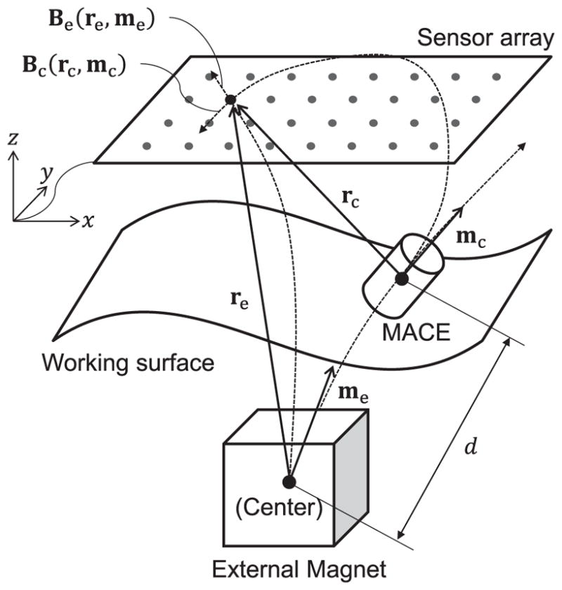
Schematic drawing of the application scenario. A MACE is manipulated by an external magnet in the 3-D space. The objective of this paper is to estimate the position (rc) and orientation (mc) of the MACE under the effect of the external magnetic field.
The magnetic sensors experience magnetic fields both from the MACE and the external magnet. Those magnetic fields are expressed as B-fields in (1):
| (1) |
where Bs is the measured B-field at a sensor, Bc is the B-field of the MACE, and Be is the B-field of the external magnet. A simple way to estimate a pure Bc is to subtract Be from Bs. To subtract, we should model Be, and the general way to model a magnetic field is to use the magnetic dipole equation in a coordinate-free form,
| (2) |
where μ0 is the permeability of free space, r is the position vector (with associated unit vector r̂) from the magnetic source to the point of interest, m is the magnetic moment vector of the magnetic source, and I is a 3×3 identity matrix. Thus, Be can be expressed using (2) as
| (3) |
where re is the position vector from the external magnet to the sensor position and me is the magnetic moment vector of the external magnet. However, in actuality, we cannot measure the exact re and me, which results in the B-field error. Also the real magnetic field includes multi-pole magnetic fields, which are not modeled in (2). Thus, (1) can be rewritten as
| (4) |
Here the B-field error, Berr, is specified as
| (5) |
where rerr and merr are a positioning error and a magnetic moment measurement error of the external magnet, respectively. In (5), those two dipole terms scale with ||re||−3 as described in (2), and the quadrupole and hexapole terms scale with ||re||−5 and||re||−7, respectively [26].
Because the error terms in (5) are inversely proportional to the distance, they reduce as the external magnet moves farther from the sensor array. Conversely, the B-field from the MACE increases as the MACE gets closer to the sensor array. To express this relationship, we define a new parameter, Signal Quality Ratio (SQR) in B-field, as
| (6) |
where rc is a position vector from the sensor array to the MACE and Ns is a noise level of the sensor. The magnetic field error due to multi-pole terms in (5) is negligible as they are much smaller than the dipole term in (6). Note that, assuming that Ns is negligible, SQRB is inversely proportional to the third order of the distance.
The directional differentiation of the analytical model (2) results in
| (7) |
The SQR in the second order differentiated B-field is expressed as
| (8) |
Assuming that Ns is negligible, SQRL is inversely proportional to the fifth order of the distance ratio. Because the ||re|| is larger than ||rc||, SQRL is always higher than SQRB. The more the B-field is differentiated, the better SQR is achieved because of the scaling law. However, the number of the differentiation is limited by the number of the sensor elements, and the noise is magnified by the differentiation. In this paper, the second order differentiation was sufficient for the given number of the sensors and the noise level of the sensors.
Another advantage of using the second order directional differentiation is that we can calculate the vertical directional differentiation using a lateral 2-D array of mono-axial Hall-effect sensors. Equation (9) is always valid at all positions based on Maxwell’s equations in the absence of current or a changing electric field,
| (9) |
Equation (9) shows that the second order derivative in the z-direction equals a negative sum of those in the x- and y-directions. Though Hall-effect sensors in the XY-plane measure the magnetic fields in the z-direction, the second order derivative in the z-direction can be calculated without using multiple layers in the z-direction based on the above property. Here, we define the second order z-directional derivative K as
| (10) |
where Bz is a z-directional component of B. In the two-dimensional sensor array, K is calculated by using the magnetic field of the neighboring sensors. Using the five-point stencil finite difference method, K at the sensor node (i, j), or Ki,j, is expressed as
| (11) |
where Bi,j is the z-directional component of the B-field measured by the sensor at the node (i, j), and h is the nodal distance between neighboring sensors.
We conducted experiments to compare SQRL with SQRB in order to verify the analysis performed in (6) and (8). Because our setup measures only the z-directional components of the B-field, we defined two new terms, SQRz,B and SQRz,L as (12) and (13).
| (12) |
where n is the number of sensors, is the z-directional magnetic field from the MACE, and is the z-directional magnetic field from the electromagnet; each is measured by the sensor at node (i, j) in the absence of the other’s magnetic field. is the z-directional magnetic field of the electromagnet assuming the dipole model.
| (13) |
where and are the second derivatives of the z-directional magnetic fields from the MACE and the external magnet, respectively. Both of these are calculated using (11). is the second derivative of the z-directional magnetic field of the external magnet assuming the dipole model, which is calculated using (7).
Although SQRz represents only the z-directional components of SQR, the comparison of SQRz,L and SQRz,B indirectly represents the effect of the scaling law in (6) and (8) on the signal quality. In the experiments, we set mc to (0, 0, 0.45) A·m2 and me to (0, 0, 30.0) A·m2, and both SQRz,B and SQRz,L are measured for 10 seconds, then averaged.
Figure 3 shows that SQRL is higher than SQRB where the distance ratio (||re||/||rc||) is larger than 1. This means that SQRL becomes a clearer standard than SQRB does. Especially, as rc becomes smaller and re becomes larger, SQRL increases exponentially, whereas SQRB stays in low level. These experimental results show that the proposed method gives better signal information than the B-field subtraction method.
Fig. 3.
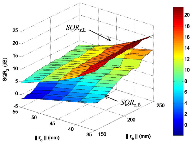
Experimental comparison of SQRz,B and SQRz,L. SQRz,L is higher than SQRz,B in all regions. The z-directional distance from the MACE and the external magnet were set from 30 mm to 75 mm and 160 mm to 230 mm with 5 mm increments, respectively. The electromagnet generated 1 mT B-field at the center of the array in the +z-direction. The measurement was done for 10 seconds.
C. Algorithm
The developed algorithm finds the optimal rc and mc by minimizing a cost function using the Levenberg-Marquardt Algorithm (LMA). LMA is a trust region based optimization method that uses the steepest descent method for global convergence and Newton’s method (quadratic method) for local convergence in a way that gives smooth transition between them [27]. This optimization solver is known as the efficient and effective solution for a magnetic marker localization problem [28]. The cost function is defined as
| (14) |
where Ki,j is the second z-directional derivative of the B-field based on the measured data at the sensor node number (i, j) and is the MACE’s modeled second z-directional derivative of the B-field at the sensor node number (i, j). and are computed by using the following analytical equation, which is derived from (2),
| (15) |
where mz is the z-directional component of m and rz is the z-directional component of r.
Fig. 4 shows a flow chart of the developed algorithm, and describes how each term of the cost function is calculated. The goal of the algorithm is to estimate the optimal rc and mc minimizing the cost function, (14). First, the measured magnetic field (Bi,j) is transformed to the second derivative (Ki,j) by using (11). Second, the electromagnet’s input current (Ie) gives the estimate of its magnetic moment (me). Using the calculated re, me, and (15), we can obtain the second derivative of the electromagnet’s B-field ( ). The key of the cost function is the last term ( ). The optimal rc and mc of the previous iteration become the initial conditions for the current rc and mc. The terms are calculated by (15), and iteratively updated by the optimization. The new optimal rc and mc that minimize the cost function become the current position and orientation of the capsule.
Fig. 4.
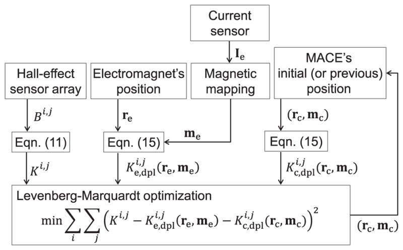
Block diagram of the main localization algorithm. The proposed algorithm minimizes the cost function to find the position (rc) and orientation (mc) of the MACE. Initial position and orientation of the MACE are continuously updated by the algorithm for the real-time tracking. Measured B-field’s second derivative is calculated using Laplacian of the B-field, and the estimated second derivative of the B-field is calculated using the second derivative form of the dipole equation.
III. Experiments
We conducted experiments to evaluate the accuracy and reliability of the developed localization methods. Since water and biological tissue do not affect the low frequency magnetic field, our simple and magnetically transparent experimental setup is applicable to the magnetic capsule endoscopy. As a single magnet works as a magnetic source for both actuation and localization in the proposed method, The MACE was represented by a box shaped (6.4×6.4×12.8 mm3) NeFeB magnet with 0.45 A·m2 magnetic moment. The work space for the MACE was given as 70(w)×70(d)×50(h) mm3 below the sensor array. A plane with a slope was used for the working surface in the experiment (Fig. 5(b)). The external magnet, which was positioned 20 cm below the array, generated a 2.5 mT rotating magnetic field at the center of the MACE for climbing rolling locomotion. While it is rolling from the initial position, (20, −20, −35) mm, to the final position, (−18, 18, −20) mm, the proposed method ran in real-time at 200 Hz (limited by LMA loop speed) to track the position and orientation of the MACE. The B-field subtraction method ran in parallel with the proposed method for comparison. For the ground truth position and orientation, two video cameras recorded the MACE with visual markers (Fig. 5(a)). 5-D visual reference data was extracted using an image processing software [29].
Fig. 5.

Experimental setup and the dynamic motion of the MACE. (a) The MACE has markers on its surface. We reconstructed the position and orientation of the moving robot using the markers in images. (b) The MACE traversed the slope with the external magnetic actuation that gave rolling locomotion to the MACE.
A total of 10 experiments were conducted, and each experiment took approximately 6 seconds for the MACE to traverse the surface. Each trial had the same initial condition and planned trajectory. All the manipulation and localization were done autonomously by the pre-programmed codes in LabView (National Instruments co.). Distance errors were measured by Euclidean distance and angular errors were measured by orientation vector difference using visual reference data.
Table II shows the summarized experimental results. Overall, the proposed method is more accurate than the B-field subtraction method. Its total average errors were 2.1±0.8 mm (distance) and 6.7±4.3° (angular), respectively, while the errors of the B-field subtraction method were 2.6±1.3 mm and 8.3±6.5°, respectively. The fact that its maximum errors (4.7 mm and 30°) were much smaller than the others (10.5 mm and 50.3°) means that the proposed method is more stable. Figure 6(a)–(c) show the worst case error of the experimental trials. The proposed method more closely and more stably tracked the ground truth position than the B-field subtraction method did (see the abruptly increasing position errors near the initial position in Fig. 6(a)).
TABLE II.
Dynamic Motion Tracking Experiment Results
| Number of trials=10* | Position error (mm) | Orientation error (°) | ||||
|---|---|---|---|---|---|---|
| Avg.±Std.** | Min | Max | Avg.±Std.** | Min | Max | |
| Proposed method | 2.1±0.8 | 0.07 | 4.7 | 6.7±4.3 | 0.03 | 30.0 |
| B-field subtraction method | 2.6±1.3 | 0.4 | 10.5 | 8.3±6.5 | 0.07 | 50.3 |
Each trial had the same initial condition and trajectory.
The total average of the 10 experiments.
Fig. 6.

Result of the dynamic motion tracking experiment (the worst case). (a) The proposed method tracked the MACE in real-time with the external magnetic actuation. (b) While the B-field subtraction method had a significant loss of track near the starting point and errors in the middle of the track, the proposed method tracked the MACE’s motion through the whole path with the minor error. (c) As the distance ratio, ||re||/||rc||, increases, the localization error shows a decreasing trend. The proposed method shows less positioning error than the B-field subtraction method in almost all ranges. The error fluctuates because of the rotating magnetic field of the MACE.
Error reduction by the differentiation explains the improved accuracy. In the B-field subtraction method, the position and orientation of the MACE fluctuate because of the rotating external magnetic field. This error is due to the magnetic field error in the analytical magnetic model in (5). This factor is still non-negligible and results in poor accuracy. However, by taking the proposed second order differentiation, those fluctuations are significantly reduced as shown in the plot. This method improves z-directional localization accuracy significantly, although it does not impact the x- and y-position accuracy (Fig. 6(b)) as it is applied in z-direction.
The distance ratio, ||re||/||rc||, is critial to localization accuracy. Although our nonlinear optimization method does not show an explicit relationship between SQR values and localization error, Fig. 6(c) shows that larger distance ratios correspond to smaller localization errors, and that the second derivative method yields smaller errors. These results are consistent with the theoretical analysis in (6) and (8).
IV. Discussion
The developed real-time localization method gives accurate estimations of the position and orientation of a magnetically manipulated robot. This method does not require internal sensors, and allows to remain the mechanical and electrical configuration of the robot simple, which is useful for an untethered magnetic robot for medical applications where optical tracking is not possible. Table III shows the detailed comparison with other magnetic localization methods. Even though the effective distances in the experiments are different, the proposed localization method shows the smallest position error and the fastest speed for controlling a capsule robot in real-time compared to the other magnetic localization methods.
TABLE III.
Comparison of the Magnetic Localization Methods
| Popek et al. [23] | Di Natali et al. [24] | Yim et al. [25] | The proposed method | Than et al.* [30] [31] | |
|---|---|---|---|---|---|
| Internal Sensor(s) | 6 Hall-effect sensors | 6 Hall-effect sensors + 1 tri-axial accelerometer | 1 Hall-effect sensor | None | None |
| External Sensor(s) | None | None | None | 64 Hall-effect sensors | 2 pairs of gamma ray detectors |
| Position Error (mm) | 11 | 3.4±3.2 | 2.0 | 2.1±0.8 | 0.4 |
| Orientation Error (°) | 11 | 19±50 | 5±1.2 | 6.7±4.3 | 2 |
| Real-time (Loop speed) | No | Yes (14 ms) | No | Yes (5 ms) | Yes (2–3 ms) |
| Effective localization Range (mm) | 136.0 – 144.0** | 0 – 150 | 44.2 – 57.2 | 5 – 50 | 200 – 400 |
Non-magnetic localization method (positron emission marker dectection).
Range in the experiment. Effective localization range is not shown explicitly in the paper.
However, the proposed localization method would have a limited clinical application because of the short effective distance (< 50 mm). Beyond 50 mm, SQR values drop below 5 dB (see Fig. 3) even with the second derivative method. This means the noise and error terms occupy more than 36% of the whole measured signal. With such poor signal conditioning, the nonlinear optimization algorithm tends to either diverge or give unreasonable estimations.
The effective distance can be increased by using lower noise Hall-effect sensors and a bigger magnet. In the experiments, we used a small magnet (6.4×6.4×12.8=524.3 mm3, NdFeB, 0.45 A · m2), but doubling the volume of a cylindrical shape, (ϕ11×11=1,045 mm3, NdFeB, 0.90 A·m2), would still be within the limits for a swallowable capsule endoscope (diameter<12 mm, length<30 mm). We simulated the effective distance as a function of the inherent sensor noise. We assumed that 20 dB is the minimum SQR level for quality localization (same as 10% error) to determine the effective distance, Seff. In the simulation, the original equations, including noise terms from (6) and (8), were used. Figure 7 shows the relationship between the inherent sensor noise and Seff. Both the B-field subtraction method and the proposed method have increased effective distances as the inherent sensor noise decreases. While the B-field subtraction method saturates at 13 cm, the second derivative method shows a maximum of 23 cm effective distance without saturation using currently existing sensors (e.g., MMC3316xMT, MESMIC co, RMS noise: 0.2 μT). Additionally, an extremely low inherent noise sensor, such as 0.02 μT RMS noise level sensors, would give nearly 30 cm of Seff, which satisfies the effective range guideline of magnetic capsule endoscopy.
Fig. 7.

Simulated effective localization range (Seff) as a function of the inherent sensor noise. With the (1, 1, 1) mm position misalignment and 1 A·m2 magnetic moment error from the external magnet, it is shown that the Seff can be extended to 23 cm with the currently existing sensors. As inherent sensor noise gets smaller, it is preferable to use the second order derivative for better accuracy and long effective localization distance. The external magnetic field on the MACE was (0, 0, 3) mT.
V. Conclusion
In this paper, we introduced a new real-time 5-D localization method for an untethered meso-scale magnetic robot, which is manipulated by a computer-controlled external electromagnetic system. The developed magnetic localization setup is a 2-D array of mono-axial Hall-effect sensors, which measure the perpendicular magnetic fields at their positions. We propose two steps for localizing the magnetic robot more accurately. First, the dipole modeled magnetic field of the electromagnet is subtracted from the measured data in order to determine the pure magnetic field from the magnetic robot. Next, the subtracted magnetic field is twice differentiated in the perpendicular direction of the array, so that the effect of the electromagnetic field in the localization process is minimized. Five variables regarding the position and orientation of the magnetic robot are determined by minimizing the error between the measured magnetic field and the modeled magnetic field in an optimization method. The resulting position error is 2.1±0.8 mm and angular error is 6.7±4.3° within the applicable range (5 cm) of magnetic field sensors at 200 Hz. The proposed localization method would be used for the position feedback control of untethered magnetic devices or robots for medical applications in the future.
Acknowledgments
This work is funded by the National Robotics Initiative award of the National Institutes of Health (NIH R01-NR014083).
Biographies

Donghoon Son (S’14) received the B.Sc. and M.Sc. degrees in mechanical engineering from Seoul National University, Seoul, Korea, in 2007 and 2009, respectively. He is working toward the Ph.D. degree in mechanical engineering with Carnegie Mellon University, Pittsburgh, PA, USA, and Physical Intelligence Department, Max-Planck Institute for Intelligent Systems, Stuttgart, Germany. His main research focus is to develop localization, calibration, and control methodologies for mesoscale magnetic robots in medical applications.

Sehyuk Yim (S’09) received the B.Eng. degree in mechanical engineering, the B.Eng. degree in electronic engineering in 2007, and the M.S. degree in mechanical engineering in 2009, all from Sogang University, Seoul, Korea, and Ph.D. degree in mechanical engineering from Carnegie Mellon University, 2012. He was a postdoctoral research associate in the mechanical engineering department at Massachusetts Institute of Technology during 2014 and 2015. As of July 2015, he is a senior research scientist at the Robotics and Media Institute of Korea Institute of Science and Technology (KIST). His research goal is to leverage physical intelligence (bio-inspired soft or functional materials, mechanically programmed smart structures, magnetic or structural self-assembly), novel actuation principles (electromagnetic actuation, hydraulic or pneumatic force transmission, shape-memory actuation) and advanced manufacturing methods (resin molding, additive manufacturing, printing, three-dimensional origami) to create minimally-designed hybrid electro-mechanical machines.

Metin Sitti (S’94-M’00-SM’08-F’14) received the B.Sc. and M.Sc. degrees in electrical and electronics engineering from Bogazici University, Istanbul, Turkey, in 1992 and 1994, respectively, and the Ph.D. degree in electrical engineering from the University of Tokyo, Tokyo, Japan, in 1999. He was a research scientist with the University of California at Berkeley, Berkeley, CA, USA, during 1999–2002. He is currently a director in Max-Planck Institute for Intelligent Systems and a professor in Department of Mechanical Engineering and Robotics Institute at Carnegie Mellon University. His research interests include small-scale physical intelligence, mobile milli- and microrobots, medical miniature robots, bio-inspired materials and locomotion, and micro/nanomanipulation.
Dr. Sitti is an IEEE Fellow. He received the SPIE Nanoengineering Pioneer Award in 2011 and NSF CAREER Award in 2005. He received the IEEE/ASME Best Mechatronics Paper Award in 2014, the Best Poster Award in the Adhesion Conference in 2014, the Best Paper Award in the IEEE/RSJ International Conference on Intelligent Robots and Systems in 2009 and 1998, the first prize in the World RoboCup Micro-Robotics Competition in 2012 and 2013, the Best Biomimetics Paper Award in the IEEE Robotics and Biomimetics Conference in 2004, and the Best Video Award in the IEEE Robotics and Automation Conference in 2002. He is the editor-in-chief of Journal of Micro-Bio Robotics.
Footnotes
The content is solely the responsibility of the authors and does not necessarily represent the official views of the National Institutes of Health.
Contributor Information
Donghoon Son, Email: dhson@cmu.edu, Department of Mechanical Engineering, Carnegie Mellon University, PA 15213 USA and Physical Intelligence Department, Max-Planck Institute for Intelligent Systems, 70569 Stuttgart, Germany.
Sehyuk Yim, Email: sehyuky@kist.re.kr, Performed this research at Carnegie Mellon University, Pittsburgh, PA 15213 USA. Now, he is with the Robotics and Media Institute, Korea Institute of Science and Technology (KIST), Seoul, South Korea.
Metin Sitti, Email: sitti@is.mpg.de, Department of Mechanical Engineering, Carnegie Mellon University, PA 15213 USA and Max-Planck Institute for Intelligent Systems, 70569 Stuttgart, Germany.
References
- 1.Sendoh M, Ishiyama K, Arai KI. Fabrication of magnetic actuator for use in a capsule endoscope. IEEE Transactions on Magnetics. 2003 Sep;39(5):3232–3234. [Google Scholar]
- 2.Ciuti G, Valdastri P, Menciassi A, Dario P. Robotic magnetic steering and locomotion of capsule endoscope for diagnostic and surgical endoluminal procedures. Robotica. 2009 Oct;28(02):199. [Google Scholar]
- 3.Nelson BJ, Kaliakatsos IK, Abbott JJ. Microrobots for minimally invasive medicine. Annual review of biomedical engineering. 2010 Aug;12:55–85. doi: 10.1146/annurev-bioeng-010510-103409. [DOI] [PubMed] [Google Scholar]
- 4.Toennies JL, Tortora G, Simi M, Valdastri P, Webster RJ. Swallowable medical devices for diagnosis and surgery: the state of the art. Proceedings of the Institution of Mechanical Engineers, Part C: Journal of Mechanical Engineering Science. 2010 Jan;224(7):1397–1414. [Google Scholar]
- 5.Mahoney AW, Abbott JJ. Managing magnetic force applied to a magnetic device by a rotating dipole field. Applied Physics Letters. 2011;99(13):134–103. [Google Scholar]
- 6.Than TD, Alici G, Zhou H, Li W. A review of localization systems for robotic endoscopic capsules. IEEE transactions on biomedical engineering. 2012 Sep;59(9):2387–99. doi: 10.1109/TBME.2012.2201715. [DOI] [PubMed] [Google Scholar]
- 7.Sitti M, Ceylan H, Hu W, Giltinan J, Turan M, Yim S, Diller E. Biomedical applications of untethered mobile milli/microrobots. Proceedings of the IEEE. 2015;103(2):205–224. doi: 10.1109/JPROC.2014.2385105. [DOI] [PMC free article] [PubMed] [Google Scholar]
- 8.Lee JS, Kim B, Hong Y-S. A flexible chain-based screw propeller for capsule endoscopes. International Journal of Precision Engineering and Manufacturing. 2009 Oct;10(4):27–34. [Google Scholar]
- 9.Carpi F, Kastelein N, Talcott M, Pappone C. Magnetically controllable gastrointestinal steering of video capsules. IEEE transactions on bio-medical engineering. 2011 Feb;58(2):231–4. doi: 10.1109/TBME.2010.2087332. [DOI] [PubMed] [Google Scholar]
- 10.Yim S, Sitti M. Design and rolling locomotion of a magnetically actuated soft capsule endoscope. IEEE Transactions on Robotics. 2012;28(1):183–194. doi: 10.1109/TRO.2013.2266754. [DOI] [PMC free article] [PubMed] [Google Scholar]
- 11.Yim S, Gultepe E, Gracias D, Sitti M. Biopsy using a magnetic capsule endoscope carrying, releasing and retrieving untethered microgrippers. IEEE Transactions on Biomedical Engineering. 2014;61(2):513–521. doi: 10.1109/TBME.2013.2283369. [DOI] [PMC free article] [PubMed] [Google Scholar]
- 12.Yim S, Sitti M. Shape-programmable soft capsule robots for semi-implantable drug delivery. IEEE Transactions on Robotics. 2012 Oct;28(5):1198–1202. [Google Scholar]
- 13.Yim S, Goyal K, Sitti M. Magnetically actuated soft capsule with the multimodal drug release function. IEEE transactions on Mechatronics. 2013;18(4):1413–1418. doi: 10.1109/TMECH.2012.2235077. [DOI] [PMC free article] [PubMed] [Google Scholar]
- 14.Petruska AJ, Abbott JJ. Omnimagnet: an omnidirectional electromagnet for controlled dipole-field generation. IEEE Transactions on Magnetics. 2014 Jul;50(7):1–10. [Google Scholar]
- 15.Plotkin A, Paperno E. 3-D magnetic tracking of a single sub-miniature coil with a large 2-D array of uniaxial transmitters. IEEE Transactions on Magnetics. 2003 Sep;39(5):3295–3297. [Google Scholar]
- 16.Hu C, Meng M. 3-Axis magnetic sensor array system for tracking magnet’s position and orientation. Intelligent Control and Automation. 2006;2:5304–5308. [Google Scholar]
- 17.Meng MH, Mandal M. A Linear algorithm for tracing magnet position and orientation by using three-axis magnetic sensors. IEEE Transactions on Magnetics. 2007 Dec;43(12):4096–4101. [Google Scholar]
- 18.Li B, Song S, Meng MQ-H, Qiao W, Hu C, Ren H, Yu H, Zhang Q, Xu G. 6-D localization and orientation for wireless capsule endoscope using annular magnet. IEEE Transactions on Magnetics. 2014;50(9) [Google Scholar]
- 19.Aoki I, Uchiyama A, Arai K. Detecting system of position and posture of capsule medical device. 7,751,866 B2, 07 6. US Patent. 2010
- 20.Hashi S, Yabukami S, Kanetaka H, Ishiyama K, Arai K. Numerical study on the improvement of detection accuracy for a wireless motion capture system. IEEE Transactions on Magnetics. 2009 Jun;45(6):2736–2739. [Google Scholar]
- 21.Hashi S, Yabukami S, Kanetaka H, Ishiyama K, Arai KI. Wireless magnetic position-sensing system using optimized pickup coils for higher accuracy. IEEE Transactions on Magnetics. 2011 Oct;47(10):3542–3545. [Google Scholar]
- 22.Kim MG, Hong YS, Lim EJ. Position and orientation detection of capsule endoscopes in spiral motion. International Journal of Precision Engineering and Manufacturing. 2010 Apr;11(1):31–37. [Google Scholar]
- 23.Popek K, Mahoney A, Abbott J. Localization method for a magnetic capsule endoscope propelled by a rotating magnetic dipole field. IEEE International Conference on Robotics and Automation (ICRA) 2013:5328–5333. [Google Scholar]
- 24.Di Natali C, Beccani M, Valdastri P. Real-Time pose detection for magnetic medical devices. IEEE Transactions on Magnetics. 2013 Jul;49(7):3524–3527. [Google Scholar]
- 25.Yim S, Sitti M. 3-D localization method for a magnetically actuated soft capsule endoscope and its applications. IEEE Transactions on Robotics. 2013;29(5):1139–1151. doi: 10.1109/TRO.2013.2266754. [DOI] [PMC free article] [PubMed] [Google Scholar]
- 26.Petruska AJ, Abbott JJ. Optimal permanent-magnet geometries for dipole field approximation. IEEE Transactions on Magnetics. 2013 Feb;49(2):811–819. [Google Scholar]
- 27.Schlageter V, Besse P, Popovic RS, Kucera P. Tracking system with five degrees of freedom using a 2D-array of Hall sensors and a permanent magnet. Sensors and Actuators A: Physical. 2001;92(1–3):37–42. [Google Scholar]
- 28.Hu C, Meng MQH, Mandal M. Efficient magnetic localization and orientation technique for capsule endoscopy. International Journal of Information Acquisition. 2005 Mar;02(01):23–36. [Google Scholar]
- 29.Hedrick TL. Software techniques for two- and three-dimensional kinematic measurements of biological and biomimetic systems. Bioinspiration & biomimetics. 2008 Sep;3(3) doi: 10.1088/1748-3182/3/3/034001. [DOI] [PubMed] [Google Scholar]
- 30.Than TD, Alici G, Harvey S, Zhou H, Li W. Concept and simulation study of a novel localization method for robotic endoscopic capsules using multiple positron emission markers. Medical Physics. 2014 Jul;41(7):072501. doi: 10.1118/1.4881316. [DOI] [PubMed] [Google Scholar]
- 31.Than TD, Alici G, Harvey S, O’Keefe G, Zhou H, Li W, Cook T, Alam-Fotias S. An Effective Localization Method for Robotic Endoscopic Capsules Using Multiple Positron Emission Markers. IEEE Transactions on Robotics. 2014;30(5):1174– 1186. [Google Scholar]