Abstract
Traditionally, satellite instruments that measure Earth-reflected solar radiation in the visible and near infrared wavelength regions have been calibrated for radiance responsivity in a two-step method. In the first step, the relative spectral response (RSR) of the instrument is determined using a nearly monochromatic light source such as a lamp-illuminated monochromator. These sources do not typically fill the field-of-view of the instrument nor act as calibrated sources of light. Consequently, they only provide a relative (not absolute) spectral response for the instrument. In the second step, the instrument views a calibrated source of broadband light, such as a lamp-illuminated integrating sphere. The RSR and the sphere absolute spectral radiance are combined to determine the absolute spectral radiance responsivity (ASR) of the instrument. More recently, a full-aperture absolute calibration approach using widely tunable monochromatic lasers has been developed. Using these sources, the ASR of an instrument can be determined in a single step on a wavelength-by-wavelength basis. From these monochromatic ASRs, the responses of the instrument bands to broadband radiance sources can be calculated directly, eliminating the need for calibrated broadband light sources such as integrating spheres. In this work, the traditional broadband source-based calibration of the Suomi National Preparatory Project (SNPP) Visible Infrared Imaging Radiometer Suite (VIIRS) sensor is compared with the laser-based calibration of the sensor. Finally, the impact of the new full-aperture laser-based calibration approach on the on-orbit performance of the sensor is considered.
Keywords: Suomi NPP, VIIRS, radiance, prelaunch calibration
1. INTRODUCTION
SNPP VIIRS and the successor Joint Polar Satellite Systems (JPSS) VIIRS instruments are designed to provide data continuity with the Moderate-resolution Imaging Spectroradiometer (MODIS) instruments from the National Aeronautics and Space Administration's (NASA's) Earth Observing System (EOS) (ref. 1). VIIRS incorporates a substantial hardware heritage from MODIS, including its calibration subsystems (refs. 1, 2), which are flight-proven designs. The VIIRS sensor is a 22-band instrument with nine spectral bands in the visible and near infrared, eight spectral bands in the short-wave and mid-wave infrared, and four bands in the long-wave infrared (ref. 3). The wavelengths for the spectral bands extend from 412 nm to 12.013 μm (ref. 3). Nominal center wavelengths and bandpasses for the 7 visible (Vis) and near-infrared (NIR) bands discussed in this work are given in Table 1. There are 16 detectors in each band at the focal plane.
Table 1.
Nominal center wavelengths and bandwidths from the SNPP VIIRS Performance Specifications.
| Band | Center Wavelength (nm) | Bandwidth (nm) |
|---|---|---|
| M1 | 410 | 20 |
| M2 | 443 | 15 |
| M3 | 486 | 20 |
| M4 | 550 | 20 |
| M5 | 672 | 20 |
| M6 | 748 | 15 |
| M7 | 865 | 40 |
The pre-launch calibration of SNPP VIIRS by the instrument vendor closely mimicked the pre-launch calibration of the MODIS instruments. A Spectral Measurement Assembly (SpMA), based on a lamp-illuminated 0.25 m double grating monochromator, was used to measure the VIIRS bands’ RSRs. A lamp-illuminated spherical integrating sphere source (SIS), the SIS100 (ref. 4), was used to determine band gains, converting RSRs into ASRs. The SIS100 radiances, combined with the VIIRS sensor bands’ pre-thermal vacuum (pre-TVAC) RSRs, provide calibrated band-averaged radiance responsivities for the visible and near infrared bands.
The past decade has seen the development of a laser-based radiometric calibration facility at the National Institute of Standards and Technology (NIST), the Facility for Spectral Irradiance and Radiance Responsivity Calibrations using Uniform Sources (SIRCUS) (ref. 5). SIRCUS incorporates wavelength-tunable lasers coupled into sources, typically integrating spheres or collimators, for radiance (and irradiance) responsivity calibrations of instruments. The radiometric scales are held on calibrated transfer standard detectors traceable to primary national radiometric standards at the National Institute of Standard and Technology (NIST).
There are three principal advantages to using the laser-based source approach over the historical SpMA/lamp-illuminated integrating sphere approach. The first advantage is available flux; the tunable laser systems provide tens to hundreds of mW at a particular wavelength, three or more orders of magnitude greater flux than lamp-monochromator systems. The greater flux enables Out-of-Band response to be determined, facilitates scattered light and optical cross-talk characterizations of systems, and offers the possibility of solar-level illumination for sensors like VIIRS that use the sun as an on-orbit calibration source. With the lasers introduced into a SIS, the sensor's entrance pupil can be uniformly illuminated with radiance levels approaching or exceeding predicted on-orbit radiances. With the conventional lamp-monochromator approach, the radiant flux is too low for full aperture illumination. Consequently, conventional sources used to determine the sensor's RSR typically under-fill the instrument's field-of-view and a piece-parts approach must be used to determine the system-level RSR. Second, the radiance of the SIRCUS SIS at each wavelength is known with very low uncertainties, a factor of 5 or less than the uncertainty in the broad-band lamp-illuminated SIS radiance. Finally, the wavelength of the laser sources is known to better than 0.01 nm, compared with a 0.1 nm uncertainty typical in monochromator-based systems. Together, these advantages offer the possibility of calibrating satellite sensors with lower uncertainty than is possible using historical calibration approaches.
To evaluate the potential of the new calibration approach for satellite sensors, the SNPP Project management group at NASA's Goddard Space Flight Center (GSFC) and the Integrated Program Office (IPO) at the National Oceanic and Atmospheric Administration (NOAA) funded a Special Test of VIIRS using a portable version of SIRCUS at the SNPP spacecraft manufacturer's facility (Ball Aerospace and Technologies Corporation, BATC) in early 2010. This test was performed immediately after the integration of the completed flight instrument onto the spacecraft platform. In the following sections, the instrument visible channels’ band responsivities from testing at the instrument manufacturer's facility (using the conventional two-step approach) are compared with the Special Test at the spacecraft manufacturer's facility (using the laser-based approach). Detector-to-detector differences, optical cross-talk and the uncertainties in the determination of the VIIRS sensor visible and near infrared band responsivities are presented. The comparison of these two sets of band responsivities engenders a discussion of the Out-of-Band components of the VIIRS spectral responses and their effects on the dependence of the outputs of the bands to the spectral distributions of the radiances viewed.
2. TRAVELING SIRCUS AT BALL AEROSPACE
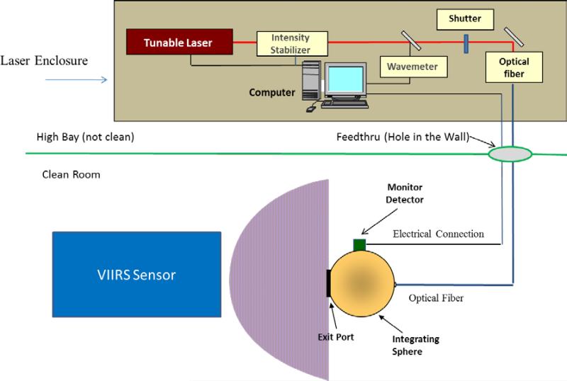
The SIRCUS facility at NIST has been described in detail previously (ref. 5); a similar configuration was used during VIIRS sensor testing at BATC, shown schematically in Fig. 1. The SIRCUS setup provided monochromatic radiance from a 76.2 cm diameter SIS equipped with a 25.4 cm diameter aperture. Two calibrated Gershun-tube radiance meters were used at BATC to provide a calibration of two silicon photodiodes mounted on the SIS wall. The calibration related the monitor signal from the photodiodes to the sphere radiance. The sphere-mounted photodiodes were calibrated pre- and post-VIIRS measurements using the NIST working standard radiance meters in the BATC high bay outside the clean room. During VIIRS measurements of the sphere, the radiance was determined solely by the monitor detectors. Before and after the measurement program at BATC, the Gershun-tube radiance meters were calibrated at NIST.
Figure 1.
Schematic diagram of the Traveling SIRCUS facility.
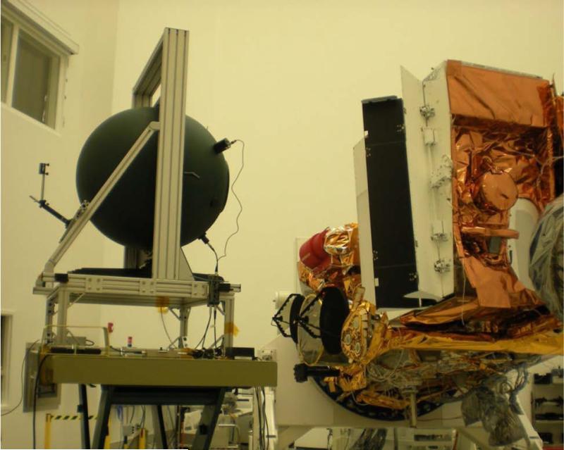
The integrating sphere was aligned to the VIIRS sensor nadir (Earth-view) port in the BATC clean room (Fig. 2). The tunable laser system remained in the high bay area outside the clean room. Radiant flux from the laser sources was coupled to the SIS using steel-jacketed 200 μm core diameter silica-silica optical fiber. A beamsplitter in the optical path sent a small portion of the laser radiation into a wavemeter that measured the wavelength of the radiation. An electronic shutter in the optical path could be remotely controlled, allowing ambient signal levels to be routinely acquired. Room lights were kept off during testing.
Figure 2.
Photograph of the Traveling SIRCUS SIS in front of the SNPP VIIRS sensor nadir doors
During testing, the VIIRS telescope was stationary (non-rotating) and VIIRS continuously acquired data at a fixed integration time. SIRCUS data sets, consisting of a timestamp, the laser wavelength, and the monitor signals, were obtained concurrently with VIIRS acquisitions. The shutter was closed while the wavelength was changed, providing a beginning and end of wavelength ambient signal in the data streams. These ambient signals combined with timestamps in the data sets facilitated the proper merging of SIRCUS and VIIRS data sets. Because the VIIRS integration time was constant, the instrument output is recorded as a digital numbers (DN) rather than a DN/unit time. The DNs from the dark periods were subtracted to provide the net DNs for each radiance level from the sphere. For each measurement, the radiance from the SIRCUS sphere, in W m−2 sr−1, and the VIIRS net DNs are combined to give an absolute spectral response (ASR), in DN/(W m−2 sr−1), at the laser wavelength.
3. HISTORICAL APPROACH TO RESPONSIVITY CALCULATIONS
The instrument manufacturer's calibration technique for VIIRS follows an approach that has been in use for several decades. First, the relative spectral responses of the instrument bands are determined. Then the instrument views a source with a known radiance spectrum such as a lamp-illuminated integrating sphere and the instrument readings for that view are recorded. Finally, for each band, the spectral response and the sphere radiance are combined to form a band-averaged spectral radiance, which is combined with the instrument reading for the band to provide a calibration coefficient. Additional quantities of interest include the band-center wavelength and bandwidth.
3.1. Relative Spectral Response Determination
For the laboratory calibration by the instrument manufacturer, the spectral responses for the VIIRS visible and near infrared bands (M1 through M7) were measured using the SpMA in ambient prior to TVAC testing (ref. 6). The SpMA consists of two MS257 quarter-meter monochromators used in the subtractive mode, a tungsten source or ceramic source (depending on wavelength), and collimating optics. The exit beam is collimated by a 30 cm off-axis spheroid with an effective focal length (EFL) of 125 cm. The exit slit is at tangential focus to give the sharpest image in the scan direction. This piece of equipment requires both spectral calibration and relative spectral output (RSO) characterization to minimize measurement uncertainties. The SpMA produces quasi- monochromatic light, and the band pass at a particular wavelength setting is 2 nm. For measurements of the radiant flux from the SpMA by VIIRS, there is a set of transition optics to focus the output of the SpMA onto the instrument's detectors. The focused output of the slit covers one band's detectors in width and one half of that band's detectors in length. Consequently, for the characterization of a single band, more than one measurement is required with a repositioning and refocusing of the SpMA output.
In the VIS and NIR, the source of light for the SpMA is an incandescent (tungsten) lamp. It has a peak radiance near 1000 nm with decreasing radiance on either side of the peak. This causes a spectrally dependent shape in the output from the SpMA's monochromator. To correct for this effect, a reference detector with known quantum efficiency also views the flux from the SpMA. This is done before and after the VIIRS spectral response measurements. The reference detector does not share the transition optics used in the measurements by VIIRS, so the detector monitors the relative output of the SpMA with wavelength but not the absolute value of that output. The SpMA-based spectral responses for each VIIRS band, after correction for the spectral shape of the flux from the source, is normalized to the peak value for that band's response to give an RSR.
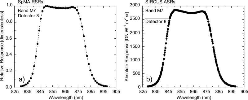
A representative RSR spectrum (for VIIRS band 7, detector 8) is shown in Fig. 3a. The RSRs are the individual points in the figure. The figure includes the wavelength region between the band's 1 % responses relative to the maximum RSR, and the band is the compilation of the RSRs. Historically, this wavelength region is defined to be the In-Band (IB) region, incorporating the bulk of the total integrated band response. Other definitions of the IB wavelength region are possible, based for example on the area under the curve formed by the individual RSRs in which the IB area incorporates a large, fixed percentage of the total area. Each definition is used to separate the response to flux with wavelengths away from the central response, called the Out-of-Band response (OOB), from the IB response. The response from the OOB component of the total instrument response can be treated as a contamination to the response in the IB response region. The Total-Band (TB) response is the summation of the IB response and the OOB response.
Figure 3.
Spectral Response Measurements for VIIRS band M7, detector 8. Measurements are shown over the In-Band response region, where the responses are 1 % of full scale and greater.
a) SpMA-based RSR and b) Tunable laser-based ASR.
A number of quantities are typically used to describe the radiometric properties of a particular band. The basic properties of a filter band are often described in terms of its center wavelength and spectral width, often called the bandwidth. Combined, these terms provide an estimate of the functional wavelength region for the band. For quantities such as spectral radiance, spectral irradiance, or the band's center wavelength, the technique of band averaging is commonly employed. Band-averaging is defined in Section 3.3 while Section 3.2 defines the bandwidth. Both the center wavelength and bandwidth can be calculated using the RSRs and their associated wavelengths.
3.2. Bandwidth
As the area under the curve, the SpMA-based bandwidth BWSpMA can be calculated via trapezoidal integration as
| (1) |
where RSR(n) is the relative spectral response for measurement n, n max is the number of measurements, and λ is the wavelength (in nm) for measurement n. For the SpMA-based RSR measurements, individual values in the IB region are separated by a constant wavelength (∆λ) and the slit widths of the monochromator are adjusted to fill that wavelength region at the VIIRS focal plane. Because the wavelength spacing ∆λ is constant, it can be pulled out of the summation. Nominal center wavelengths and bandwidths for the VIIRS bands studied in this work are given in Table 1; SpMA-derived bandwidths are given in Table 2.
Table 2.
Bandwidths and band-center wavelengths for the IB wavelength ranges of VIIRS bands M1 through M7. The values for the laboratory measurements come from the SpMA. The comparisons show the differences from SIRCUS.
| VIIRS Band | SpMA Bandwidth (nm) | SIRCUS Bandwidth (nm) | Bandwidth Difference SpMA-SIRCUS (nm) | SpMA Band-Center Wavelength (nm) | SIRCUS Band-Center Wavelength (nm) | Band-Center Wavelength Difference SpMA-SIRCUS (nm) |
|---|---|---|---|---|---|---|
| M1 | 18.53 | 19.15 | −0.62 | 410.84 | 410.75 | 0.09 |
| M2 | 14.02 | 14.08 | −0.06 | 443.63 | 443.69 | −0.06 |
| M3 | 18.87 | 18.80 | 0.07 | 486.13 | 486.34 | −0.21 |
| M4 | 19.82 | 20.04 | −0.22 | 550.94 | 550.78 | 0.16 |
| M5 | 19.61 | 19.44 | 0.17 | 671.49 | 671.59 | −0.10 |
| M6 | 14.45 | 14.36 | 0.09 | 745.41 | 745.59 | −0.18 |
| M7 | 38.74 | 38.46 | 0.28 | 862.00 | 862.10 | −0.10 |
3.3. Band-Averaged Center Wavelength and Spectral Radiance for the Band
Band-averaging uses the shape of the band to create a weighted mean of a particular quantity. For a set of measurements, the band average of quantity XBA is calculated as
| (2) |
where XBA is the quantity after averaging, and X(n) is the quantity for measurement n at wavelength λ (n). In this application, X(n) represents either wavelength or sphere radiance. Any constant multiplier for these terms can be moved outside the summations and cancelled out in the ratio if they are in both the numerator and the denominator. The RSR has been measured with a constant wavelength spacing. The calibration source radiance is known and is often interpolated to the same wavelength spacing. Equation 2 can then be expressed as
| (3) |
For the SpMA-based band-averaged center wavelength λBA (SpMA), λ(n) is substituted for X(n) in Eq. 3,
| (4) |
and for the calibration source band-averaged spectral radiance the spectral radiance of the source, LCal (n), is substituted for X(n) in Eq. 3,
| (5) |
The summation extends over the full wavelength range where there is measurable response from the band. Note that these band-averaged quantities are TB quantities, as opposed to IB quantities, where the summation is restricted to a defined spectral range corresponding to the ±1 % relative response wavelengths.
3.4. Band Responsivity Calculations
For traditional responsivity calculations, the spectral radiance value at individual wavelengths comes from the radiance spectrum of a calibrated lamp-illuminated integrating sphere and its weighted mean is the band-averaged spectral radiance. Because the summation is over the full spectral response region, the resulting quantity is the TB Band-Averaged Responsivity. The band-averaged responsivity RBA is defined to be the instrument output DN acquired while measuring the calibration source divided by the calculated band-averaged spectral radiance ,
| (6) |
Since the radiance source for the instrument manufacturer's calibration, the SIS100, is calibrated in VIIRS units, (W m−2 sr−1 μm−1), RBA has units of DN/(W m−2 sr−1 μm−1).
For this approach, there are two principal uncertainty components in the calibration of the VIIRS bands: the uncertainty in the RSRs from the SpMA measurements and the uncertainty in the spectral radiance from the calibration source, in this case the SIS100.
4. TUNABLE LASER (SIRCUS) APPROACH TO RESPONSIVITY CALCULATIONS
The laser-based measurements give an ASR at each measurement wavelength. A representative ASR spectrum (for VIIRS band M7, detector 8) is shown in Fig. 3b. Measurements over the IB response are shown, corresponding to the spectral range shown in Fig. 3a for the SpMA-based RSR measurements. The laser sources used in the calibration of the VIIRS bands are essentially delta functions and the spacing of the wavelengths in the ASR measurements can be arbitrarily small, as opposed to the SpMA approach where the step size is matched to the monochromator bandpass. As shown in Fig. 3b, the spacing of the laser-based ASR measurements near the central peak is sufficiently small to show any structure within the band response and to allow for high accuracy band integration. For direct comparison with the SpMA-based results, an ASR can be converted to a normalized RSR via division by the maximum ASR, α:
| (7) |
where α has units of DN/(W m−2 sr−1). For the ASR spectrum in Fig. 3b, for example, the maximum ASR occurs at 850.3 nm and α has a value of 2860.5 DN/(W m−2 sr−1). In the discussion in Sections 4.1 to 4.3, it is understood that ASRs and RSRs refer to SIRCUS-based measurements.
4.1. Laser-based Bandwidth Derivation
A combination of Eqs. 1 and 7 provides the SIRCUS-based bandwidth BWSIRCUS:
| (8) |
where (1/α) is applied to each ASR in the equation, maintaining the units from Eq. 1.
4.2. Calculated Band-Integrated Responsivity and Band-Averaged Center Wavelength
With the laser-based approach, there is no broad-band calibration source and the band-integrated responsivity RBI is often calculated in place of the band-averaged responsivity RBA. RBI can be obtained through trapezoidal summation,
| (9) |
where ASR(n), the ordinate, is the monochromatic ASR for measurement n, and λ(n), the abscissa, is the wavelength for that measurement.
The combination of Eqs. 3 and 7 provides the SIRCUS-based band-averaged center wavelength λBA (SIRCUS),
| (10) |
Eqs. 8 and 10 allow a direct comparison of bandwidths and band-center wavelengths derived from SIRCUS-based laboratory measurements with those quantities derived from SpMA measurements.
4.3. Spectral Radiance from a Known Source
For the traditional instrument calibration, the known spectral radiance spectrum from a lamp-illuminated integrating sphere LCal is combined with the VIIRS instrument band's ASR to provide a calibration band-averaged spectral radiance, . A combination of Eqns. 4 and 7 allows the calculation of , again assuming constant wavelength spacing:
| (11) |
5. CONVERSION FROM TOTAL-BAND TO IN-BAND VALUES
The band-averaged quantities derived in Sections 3 and 4 are all TB quantities because the summations run over the full measurement range, which should coincide with the spectral range of finite response of the instrument band. The desired values from instrument bands are most often those near the central peak of each band's response, or from the IB region. For IB quantities (band-averaged center wavelength, band-averaged radiance, band-averaged responsivity), the summation is over a finite spectral region. For VIIRS, the IB region is defined to be the spectral region between the ±1 % relative responsivity values. A measured response in the OOB region contributes a spectrally dependent error to IB quantities. To eliminate OOB biases in TB quantities, often the TB quantities are converted to give their IB counterparts by subtracting the OOB contribution from the TB quantity.
For the SIRCUS-based band-integrated responsivities, which are calculated as the sum of individual ASRs, the process is the same for calculating as for with reduced limits on the summation. The SpMA-based calculation of the Total-Band band-averaged responsivity (SpMA) in Eq. 6 includes the laboratory calculation of the instrument output in DNs. For the SpMA-based quantities, there is no simple conversion from a TB value to an IB value. The solution involves the derivation of the RSR-to-ASR scaling factor α based on measurements of a source with known spectral radiance, in this case the SIS100. The measurement equation for a VIIRS band-measurement of a calibration source is:
| (12) |
and
| (13) |
Once α is known, (SpMA) can be calculated the same way that (SIRCUS) is calculated.
6. COMPARISONS
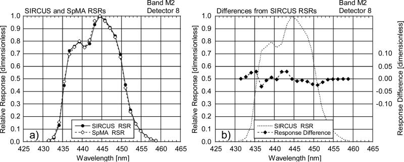
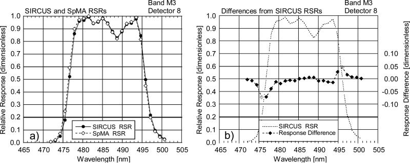
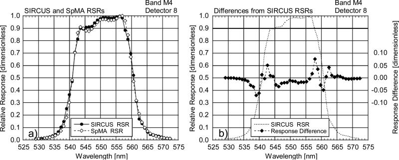
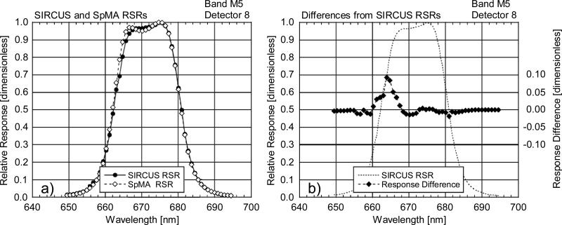
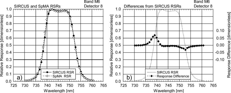
The basic values in the instrument characterization, bandwidth and band-averaged center wavelength are described in Sections 3 along with the band-averaged responsivity, the basic quantity in the instrument calibration. A comparison of instrument characterization results using the two methodologies is presented here. RSR comparisons are made at individual wavelengths; for these comparisons, the SIRCUS ASRs are converted to RSRs using Eq. 6 and then linearly interpolated to the SpMA RSR wavelengths.
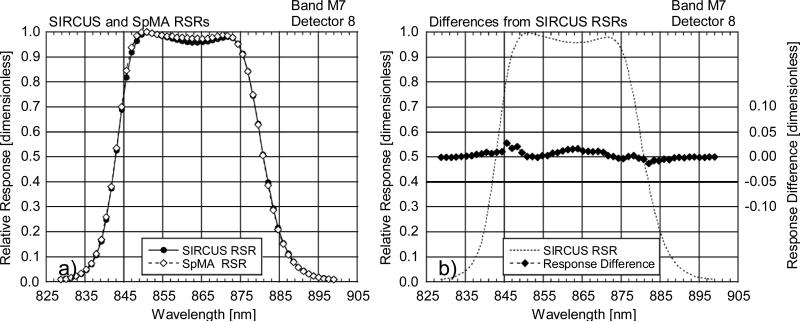
6.1. Comparison of IB RSRs
Comparisons of the IB RSR between the SpMA-based and the SIRCUS-based derivations are shown in Figs. 4-10. In these figures, the SpMA and interpolated SIRCUS RSRs are shown in the a) panels while the differences (SpMA from SIRCUS) are shown in the b) panels. The b) panels also provide an outline of the SIRCUS RSRs as a visual reference for the locations of the band edges. The features in the response differences at the band edges exhibiting a rapid change in in response in these panels could arise from wavelength mismatches between the measurements by SIRCUS and by the SpMA; the differences could also be a reflection of the finite 2 nm bandpass in the SpMA monochromator. There is a 0.5 nm uncertainty in the wavelength characterization of the VIIRS bands using the SpMA, determined from views of atomic emission line spectra. For the wavelengths in SIRCUS, the uncertainties are less than 0.01 nm for the VIIRS measurements, except for wavelengths near 500 nm where the uncertainty is 0.2 nm and the laser power is low.
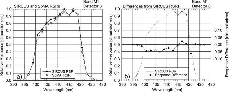
Figure 4.
Comparison of RSRs from the SpMA and SIRCUS for VIIRS band M1, detector 8. This comparison shows differences (SpMA from SIRCUS) at the SpMA wavelengths. The SIRCUS ASRs have been normalized to unity and interpolated to the SpMA wavelengths. Since SIRCUS provides a greater number of measurements per unit wavelength, the interpolation has removed details from the set of SIRCUS RSRs.
a) SIRCUS and SpMA RSRs.
b) Response Differences (SpMA from SIRCUS). The scale for the differences is given at the right-hand ordinate. The units for the differences are the same as those for the responses, themselves. An outline of the SIRCUS RSR is provided as a visual reference for the locations of the band edges.
Figure 10.
Comparison of RSRs from the SpMA and SIRCUS for VIIRS band M7, detector 8. This comparison shows differences (SpMA from SIRCUS) at the SpMA wavelengths. The SIRCUS ASRs have been normalized to unity and interpolated to the SpMA wavelengths. Since SIRCUS provides a greater number of measurements per unit wavelength, the interpolation has removed details from the set of SIRCUS RSRs.
a) SIRCUS and SpMA RSRs.
b) Response Differences (SpMA from SIRCUS). The scale for the differences is given at the right-hand ordinate. The units for the differences are the same as those for the responses, themselves. An outline of the SIRCUS RSR is provided as a visual reference for the locations of the band edges.
For band M1 in Fig. 4a the SIRCUS-measured response has a peak near 413 nm, and the SpMA peak is near 417 nm. This may result from a downward drift in the output of the SpMA lamp in the blue during the interval between the lamp's characterization (as described in Section 3.1) and the measurement of the band's RSR. Instabilities in the SpMA lamps were problems for the laboratory characterization of VIIRS. During some RSR measurements, the SpMA lamps experienced failures, and some failed before their second relative spectral output (RSO) characterization following the RSR measurements. Although it is not known with certainty, output instability might apply to the lamp used for band M1. In general, the effects of SpMA lamp instabilities remain difficult to quantify.
6.2. Bandwidth, Center Wavelength, and Responsivity Comparisons
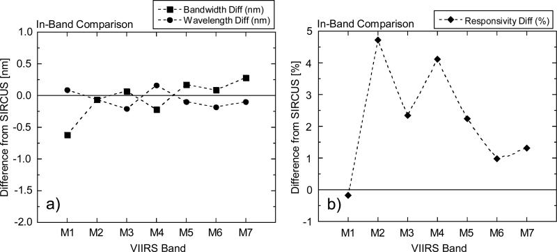
The IB bandwidths and band-center wavelengths for the SpMA and SIRCUS data sets are listed in Table 2 and the band responsivities in Table 3. The summations for the SIRCUS calculations for these comparisons use the full set of laboratory measurements and are not interpolated to the SpMA wavelengths as in the individual wavelength comparisons above. For bandwidth and band-averaged center wavelength, the differences from SIRCUS (in nm) are also listed in Table 2, and for responsivity, the percent differences from SIRCUS are listed in Table 3 and are displayed in Fig. 11. For the center wavelengths, the average differences are well within the 0.5 nm wavelength characterization uncertainty for the SpMA. For the In-Band responsivities, the differences (SpMA from SIRCUS) average 2.2 % (±1.7 %, 1 σ). This is a measure of the agreement in the calibrations from the two techniques.
Table 3.
Band responsivities for the IB wavelength ranges of VIIRS bands M1 through M7. The responsivities for the laboratory measurements come from the SpMA and the SIS100. The comparisons show the differences from SIRCUS.
| VIIRS Band | SpMA Band Responsivity1 | SIRCUS Band Responsivity1 | Responsivity Difference SpMA-SIRCUS (%) |
|---|---|---|---|
| M1 | 19.392 | 19.427 | −0.18 |
| M2 | 24.421 | 23.321 | 4.72 |
| M3 | 27.286 | 26.660 | 2.35 |
| M4 | 36.855 | 35.399 | 4.11 |
| M5 | 50.815 | 49.701 | 2.24 |
| M6 | 84.892 | 84.068 | 0.98 |
| M7 | 111.470 | 110.028 | 1.31 |
Units: DN/(W m−2 sr−1 μm−1)
Figure 11.
Differences from SIRCUS of the In-Band bandwidths, center wavelengths, and responsivities of the laboratory-based calibration by the instrument manufacturer.
a) Differences of the SpMA-based bandwidths and center wavelengths from SIRCUS (in nm).
b) Differences of the SpMA-based responsivities from SIRCUS (in percent).
6.3. Comparisons for the Total-Band Response Regions
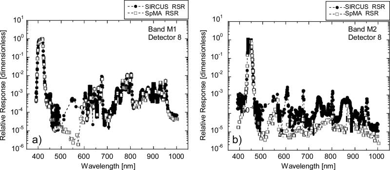
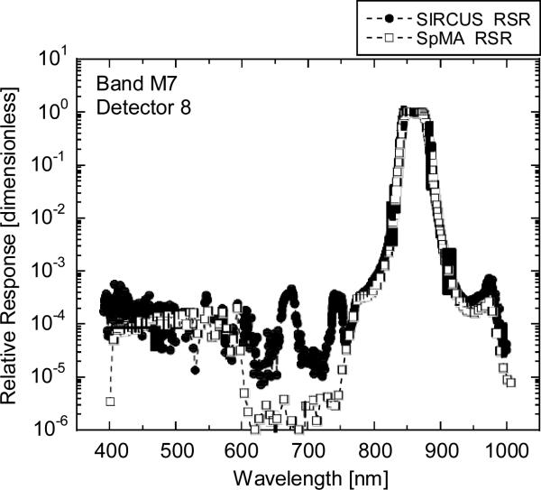
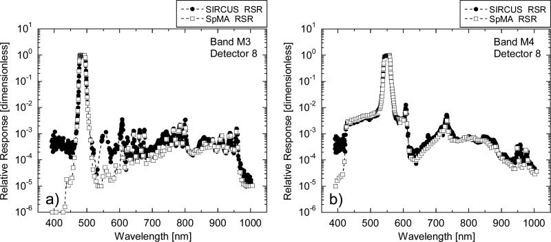
For the seven VIIRS bands, the SpMA and SIRCUS RSRs are shown over their entire sets of measurement wavelengths in Figs. 12-15. The ordinates are logarithmic, covering six orders of magnitude to improve visualization of the OOB response. For SIRCUS, the RSRs are calculated from the ASR measurements via division by α. The full data set is shown with individual data points at their measured wavelengths. Gaps in the SIRCUS measurements near 550 nm (Fig. 12 in particular) stem from low output power from the SIRCUS laser in this wavelength range.
Figure 12.
Total-Band RSRs for bands M1 and M2. The open squares come from SpMA measurements; the closed circles from SIRCUS.
a) RSRs for VIIRS band M1.
b) RSRs for VIIRS band M2.
Figure 15.
Total-Band RSRs for band M7. The open squares come from SpMA measurements; the closed circles from SIRCUS.
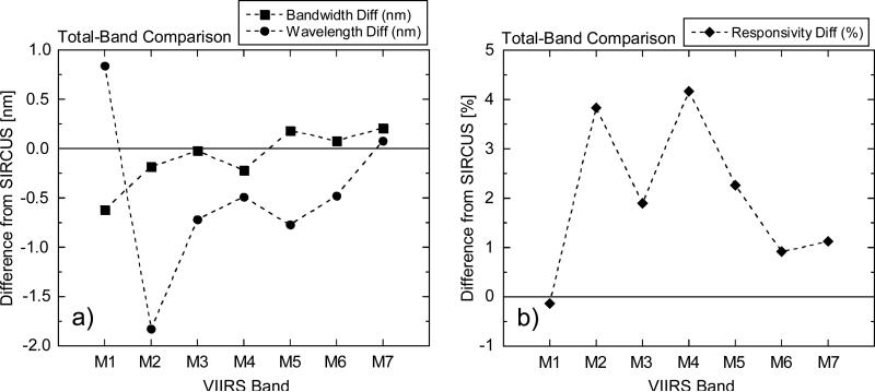
The TB values for these figures are calculated in the same manner as the IB values in Section 6.1. The bandwidths and center wavelengths for the two data sets are listed in Table 4, and the responsivities are listed in Table 5. The sets of differences are displayed in Fig. 16. There is considerably more scatter in the TB wavelength differences (Fig. 16a) relative to the IB differences (Fig. 11a). This is due in part to the limited widths of the In-Band responses relative to the overall wavelength range of the measurements (Fig 12, for example). As a result, the differences in the OOB regions become significant. In addition, the center wavelengths are calculated using weighted means, with the wavelengths as the weighting factors (see Eq. 2). For bands M1 and M2, in particular, the wavelengths in the red and near-infrared are a factor of two greater than those for the In-Band responses, amplifying the contribution of the Out-of-Band differences. For the bandwidths, on the other hand, the TB differences are in much closer agreement with their IB counterparts. For the TB responsivities, the differences (SpMA from SIRCUS) average 2.0 % (±1.6 %, 1 σ), in close agreement with the IB differences.
Table 4.
Bandwidths and center wavelengths for the TB wavelength ranges of VIIRS bands Ml through M7. The values for the laboratory measurements come from the SpMA. The comparisons show the differences from SIRCUS.
| VIIRS Band | SpMA Bandwidth | SIRCUS Bandwidth | Bandwidth Difference | SpMA Wavelength | SIRCUS Wavelength | Wavelength Difference |
|---|---|---|---|---|---|---|
| M1 | 19.08 | 19.70 | −0.62 | 421.49 | 420.65 | 0.84 |
| M2 | 14.07 | 14.25 | −0.18 | 443.92 | 445.75 | −1.83 |
| M3 | 19.06 | 19.08 | −0.02 | 488.74 | 489.46 | −0.72 |
| M4 | 20.67 | 20.89 | −0.22 | 551.58 | 552.07 | −0.49 |
| M5 | 20.18 | 20.00 | 0.18 | 670.24 | 671.01 | −0.77 |
| M6 | 14.67 | 14.59 | 0.08 | 744.62 | 745.10 | −0.48 |
| M7 | 38.89 | 38.68 | 0.21 | 861.82 | 861.74 | 0.08 |
Table 5.
Responsivities for the TB wavelength ranges of VIIRS bands M1 through M7. The responsivities for the laboratory measurements come from the SpMA and the SIS100 The comparisons show the differences from SIRCUS.
| VIIRS Band | SpMA/SIS Responsivity1 | SIRCUS Responsivity1 | Responsivity Difference (%) |
|---|---|---|---|
| M1 | 19.966 | 19.993 | −0.14 |
| M2 | 24.505 | 23.600 | 3.83 |
| M3 | 27.568 | 27.053 | 1.90 |
| M4 | 38.427 | 36.888 | 4.17 |
| M5 | 52.283 | 51.129 | 2.26 |
| M6 | 86.195 | 85.410 | 0.92 |
| M7 | 111.892 | 110.639 | 1.13 |
Units: DN/(W m−2 sr−1 μm−1)
Figure 16.
Differences from SIRCUS of the Total-Band bandwidths, center wavelengths, and responsivities of the laboratory-based calibration by the instrument manufacturer.
a) Differences of the SpMA-based bandwidths, and center wavelengths from SIRCUS (in nm).
b) Differences of the SpMA/SIS100-based responsivities from SIRCUS (in percent).
The maximum band responses (α's) are listed in Table 6. For SIRCUS, these values are determined from each set of measurements by inspection. For the manufacturer's measurements, the maximum ASRs come from the division of the responsivities by the bandwidths via Eq. 13. For the maximum ASRs, the differences (SpMA from SIRCUS) average 2.6 % (±2.0 %, 1 σ), in agreement with both the IB and the TB responsivity differences.
Table 6.
Maximum Absolute Spectral Responses (ASRs) for the Total-Band wavelength ranges of VIIRS bands M1 through M7. For SIRCUS, the maximum ASR is determined from the set of measurements by inspection. For the laboratory measurements, the maximum ASR is calculated via Eq. 13. Since the maximum ASR lies within the central response peak for each band, it is also the maximum for the In-Band wavelength ranges.
| VIIRS Band | SpMA/SIS Maximum ASR1 | SIRCUS Maximum ASR1 | Difference (%) |
|---|---|---|---|
| M1 | 1046.5 | 1014.7 | 3.13 |
| M2 | 1741.8 | 1656.2 | 5.17 |
| M3 | 1446.2 | 1418.0 | 1.99 |
| M4 | 1859.3 | 1766.1 | 5.28 |
| M5 | 2591.1 | 2556.5 | 1.35 |
Units: DN/(W m−2 sr−1)
6.4. Conversions from Total-Band to In-Band Responses
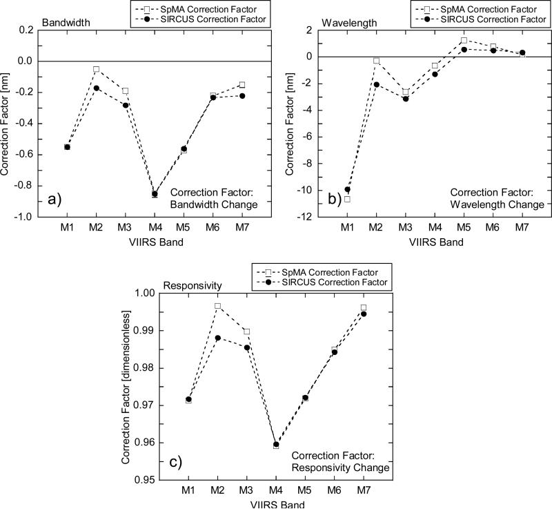
The desired values from the instrument are those near the central peak of each band's response, that is, within the In-Band wavelength region. To obtain them, it is necessary to convert the Total-Band values into their In-Band counterparts. For bandwidth and center wavelength responsivity, this can be done with the difference (in nm) of the In-Band values from their Total-Band counterparts. The corrections for bandwidth are listed in Table 7 and those for center wavelength in Table 8. The corrections are plotted in the a) and b) panels of Fig. 17, respectively.
Table 7.
TB and IB bandwidths from the instrument manufacturer's calibration and from SIRCUS. For both, the conversion factors are Total-Band bandwidths minus the In-Band values.
| VIIRS Band | SpMA In-Band Bandwidth (nm) | SpMA Total-Band Bandwidth (nm) | Bandwidth Conversion Factor (nm) | SIRCUS In-Band Bandwidth (nm) | SIRCUS Total-Band Bandwidth (nm) | Bandwidth Conversion Factor (nm) |
|---|---|---|---|---|---|---|
| M1 | 18.53 | 19.08 | −0.55 | 19.15 | 19.70 | −0.55 |
| M2 | 14.02 | 14.07 | −0.05 | 14.08 | 14.25 | −0.17 |
| M3 | 18.87 | 19.06 | −0.19 | 18.80 | 19.08 | −0.28 |
| M4 | 19.82 | 20.67 | −0.85 | 20.04 | 20.89 | −0.85 |
| M5 | 19.61 | 20.18 | −0.57 | 19.44 | 20.00 | −0.56 |
| M6 | 14.45 | 14.67 | −0.22 | 14.36 | 14.59 | −0.23 |
| M7 | 38.74 | 38.89 | −0.15 | 38.46 | 38.68 | −0.22 |
Table 8.
TB and IB center wavelengths from the instrument manufacturer's calibration and from SIRCUS. For both, the conversion factors are TB center wavelengths minus the In-Band values.
| VIIRS Band | SpMA In-Band Wavelength (nm) | SpMA Total-Band Wavelength (nm) | Wavelength Conversion Factor (nm) | SIRCUS In-Band Wavelength (nm) | SIRCUS Total-Band Wavelength (nm) | Wavelength Conversion Factor (nm) |
|---|---|---|---|---|---|---|
| M1 | 410.84 | 421.49 | −10.65 | 410.75 | 420.65 | −9.90 |
| M2 | 443.63 | 443.92 | −0.29 | 443.69 | 445.75 | −2.06 |
| M3 | 486.13 | 488.74 | −2.61 | 486.34 | 489.46 | −3.12 |
| M4 | 550.94 | 551.58 | −0.64 | 550.78 | 552.07 | −1.29 |
| M5 | 671.49 | 670.24 | 1.25 | 671.59 | 671.01 | 0.58 |
| M6 | 745.41 | 744.62 | 0.79 | 745.59 | 745.10 | 0.49 |
| M7 | 862.00 | 861.82 | 0.18 | 862.10 | 861.74 | 0.36 |
Figure 17.
Correction factors changing Total-Band bandwidths and responsivities to their In-Band counterparts.
a) Correction factors for bandwidth.
b) Correction factors for band-center center wavelength.
c) Correction factors for responsivity.
The nominal center wavelength for band M1 is 410 nm (see Table 1). The In-Band values are within 1 nm of nominal (see Table 2). However, the Total-Band center wavelengths have values near 421 nm (see Table 3). These differences come from the relatively large Out-of-Band response for the band (Fig. 12a), plus the sensitivities in the wavelength calculation described in Section 6.2. In a similar manner, there are corrections close to 2 nm for bands M2 and M3. The relative differences in the SpMA and SIRCUS wavelength corrections for band M2 in Fig 17b can also be seen in the Total-Band wavelength differences in Fig. 16a. They result from the greater Out-of-Band response from SIRCUS in Fig. 12b. A possible explanation for this difference is discussed in the Crosstalk section below.
The bandwidth corrections (Fig. 17a) are less than 1 nm in all cases. The corrections are always negative, since the bandwidth calculation is a summation (see Eq. 1), and the Total-Band RSRs have more terms than the In-Band. For band M4, the bandwidth correction has the greatest magnitude. For this band, the RSRs have values greater than 0.003 for a wavelength range of about 100 nm (see Fig. 13b). It has the greatest accumulated Out-of-Band response for the VIIRS bands.
Figure 13.
Total-Band RSRs for bands M3 and M4. The open squares come from SpMA measurements; the closed circles from SIRCUS.
a) RSRs for VIIRS band M3.
b) RSRs for VIIRS band M4.
For responsivity, the correction factor (Table 9) is multiplicative, that is, the In-Band value divided by the Total-Band value. This conversion factor is dimensionless. The factors for the bands are shown in Fig. 17c. The pattern in this panel is similar to the pattern for bandwidth in panel a) of the same figure. The RSRs and the ASRs for each band are related by the maximum ASR (α, see Eq. 7), which is constant for the band. As a result, for each band the conversion factors for bandwidth and responsivity are identical in multiplicative terms. In other words, the multiplicative corrections in Table 9 can be applied to the bandwidths in Table 7 as well.
Table 9.
TB and IB responsivities from the instrument manufacturer's calibration and from SIRCUS. For both, the conversion factors are the In-Band responsivities divided by the TB values.
| VIIRS Band |
SpMA/SIS In-Band Responsivity1 |
SpMA/SIS Total-Band Responsivity1 |
Responsivity Conversion Factor (dimensionless) |
SIRCUS In-Band Responsivity1 |
SIRCUS Total-Band Responsivity1 |
Responsivity Conversion Factor (dimensionless) |
|---|---|---|---|---|---|---|
| M1 | 19.392 | 19.966 | 0.9713 | 19.427 | 19.993 | 0.9717 |
| M2 | 24.421 | 24.505 | 0.9966 | 23.321 | 23.600 | 0.9881 |
| M3 | 27.286 | 27.568 | 0.9898 | 26.660 | 27.053 | 0.9855 |
| M4 | 36.855 | 38.427 | 0.9591 | 35.399 | 36.888 | 0.9596 |
| M5 | 50.815 | 52.283 | 0.9719 | 49.701 | 51.129 | 0.9721 |
| M6 | 84.892 | 86.195 | 0.9849 | 84.068 | 85.410 | 0.9843 |
| M7 | 111.470 | 111.892 | 0.9962 | 110.028 | 110.639 | 0.9945 |
Units: DN/(W m−2 sr−1 μm−1)
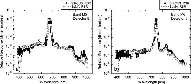
The difference between the Total-Band and In-Band responsivity responses comes from the Out-of-Band. For example, the conversion factor for the band M1 SpMA responsivities in Table 9 is 0.9713. For this band, the In-Band portion is 97.13 % of the Total-Band and the Out-of-Band is the other 2.87 %. For the band M1 SIRCUS responsivities, the partitioning of the Total-Band response is 97.17 % In-Band and 2.83 % Out-of-Band (see Table 9). For band M1, the Out-of-Band contributions for the SpMA and for SIRCUS differ by 0.04 %, a practically insignificant amount. For bands M4, M5, and M6, the differences between the SpMA and SIRCUS Out-of-Band contributions to the Total-Band are equally small, 0.05 %, 0.02 % and 0.06 %, respectively (see Table 9). In other words, the Out-of-Band differences between their SpMA and SIRCUS responses are practically insignificant for these bands as well. Thus, for band M1, the SpMA/SIRCUS differences from 450 nm to 600 nm that appear substantial in the logarithmic plot have almost no effect on the conversion from the Total-Band to the In-Band. These differences have been attributed to very weak or to missing monochromatic radiances caused by problems with the lasers used for the SIRCUS measurements. For bands M4, M5, and M6, the noise floor in the SIRCUS measurements for wavelengths below about 440 nm (see Figs. 13b, 14a, and 14b) is not a significant contributor to the Total-Band/In-Band conversion either.
Figure 14.
Total-Band RSRs for bands M5 and M6. The open squares come from SpMA measurements; the closed circles from SIRCUS.
a) RSRs for VIIRS band M5.
b) RSRs for VIIRS band M5.
For bands M2, M3, and, M7, the SpMA and SIRCUS conversion factors for responsivity differ by more significant amounts (see Table 9 and Fig. 17c). For each of these conversion factors, the SpMA value is closer to unity than its SIRCUS counterpart, indicating that the SpMA Out-of-Band contributions are smaller (Table 9). For band M2, the difference is 0.85 %, and for bands M3 and M7, the differences are 0.43 % and 0.17 %, respectively. As explained in the following section, these differences are attributed to crosstalk between bands in the instrument, an effect that the SpMA under-represents.
7. CROSSTALK
Unexpected features were observed in the VIIRS sensor response during spatial response testing of the Engineering Design Unit (EDU). Examination of the phenomenon led to its identification as crosstalk, or communication between bands. Multiple types of crosstalk were identified, each with its own pathway for band-to-band communication. The two main types crosstalk were called dynamic and static crosstalk.
Dynamic crosstalk is an electronic effect where a change in the photo-current in one band invokes a response in another band. Although this was initially the strongest effect observed, it was the easiest to mitigate by application of bonding wires to reduce a higher than expected sheet resistance in the common bias electrode of the detector array. Subsequently, dynamic crosstalk became small relative to static crosstalk.
Two types of static crosstalk were identified the VIIRS focal plane, electrical and optical. Electric crosstalk generally occurred systematically from point to point across the detector array. This phenomenon was also significant in the EDU and led to re-working of the electronics to minimize the effect. Electrical static crosstalk was found to be small in the flight instrument relative to other static effects. Optical static crosstalk, or simply optical crosstalk, occurs between a source of the scattered light (sending band) and a recipient (receiving band). In the VIIRS EDU, optical crosstalk stemmed from incident light in one band scattered at the surface or within the integrated filter array falling on a different band. It was noted that, in most cases, the sending sources were predominant over many narrow windows in the NIR region. The effects of optical crosstalk in the VIIRS flight unit during bench testing were smaller than expected based on earlier experiments with the EDU. Still, this type of crosstalk was greater for the SNPP VIIRS flight instrument than either type of electrical crosstalk. The more significant effects of optical crosstalk were limited to adjacent bands on the focal plane.
Since the spectral response measurements using the SpMA illuminated a single band at a time, crosstalk in the derived RSRs is minimal. For SIRCUS, the input radiances flooded the entire focal plane in the same manner as measurements of upwelling light from the Earth on-orbit. For VIIRS bands M2, M5, and M7, the SIRCUS-derived RSRs show responses from wavelengths greater than about 600 nm not found in the SpMA-derived RSRs. These differences were attributed to optical crosstalk. Figures 14a and 14b show a crosstalk effect near 860 nm for bands M5 and M6, respectively, while Fig. 15 show effects near 680 nm and 745 nm. For band M2 (Fig. 12b), there are several crosstalk contributions in the SIRCUS RSRs at wavelengths in the red and near infrared.
8. DETECTOR-TO-DETECTOR DIFFERENCES
The calculations in the previous sections have involved a single detector, detector 8, of each band in the focal plane. On orbit, each scan of the VIIRS mirror sweeps out 16 detectors in the along-track direction so there are 15 additional detectors per band in the focal plane. Detector 16 in the first scan is adjacent to detector 1 in the second scan, and so forth for succeeding scans. Striping occurs in the processed imagery if the differences in detector responsivities are not accounted for while differences in band-center wavelengths will impact data products if not considered. This section gives the detector-to-detector band-center wavelength and band-averaged responsivity differences for the set of band M1 detectors in the focal plane as a representative example of effects seen in all bands.
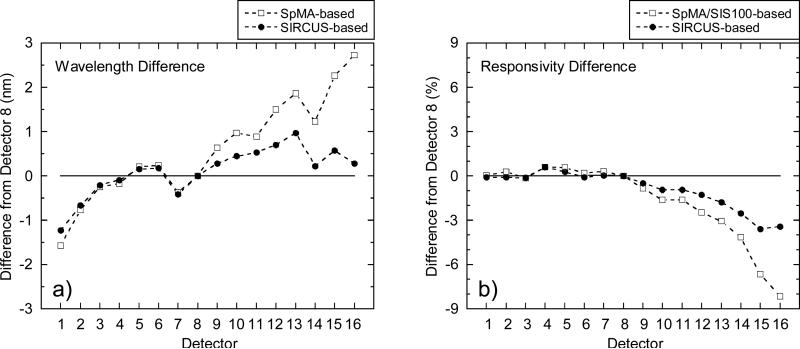
Spectral distortion in an imaging spectrograph is called smile. We keep the same terminology to refer to detector-to-detector band-center wavelength differences in the focal plane. The band-center wavelengths are calculated using Eq. 4 for the set of 16 SpMA-based RSRs and Eq. 10 for the set of 16 SIRCUS-based RSRs. The relative band-center wavelength change across the focal plane is derived relative to detector 8 by subtracting each detector's band center wavelength from detector 8's band center wavelength. For both sets of RSRs, the results are shown in Fig. 18a. For the SpMA-based band-center wavelengths, the wavelength differences increase in a roughly linear fashion from about –1.5 nm for detector 1 to almost 3 nm for detector 16. The SIRCUS-based wavelength differences agree well with the SpMA values for detectors 1 to 8. However, for detectors 9 to 16, the SIRCUS-based band-center wavelength differences flatten, with the wavelength for detector 16 about 0.3 nm greater than detector 8.
Figure 18.
Detector-to-detector differences for VIIRS band M1. The differences are normalized to detector 8. The SpMA-based differences are shown as open squares; the SIRCUS-based differences as solid circles.
a) Center wavelength differences in nm.
b) Responsivity differences in percent.
For responsivity, the individual SpMA-based responsivities are calculated using Eq. 6 and the SIRCUS-based responsivities via Eq. 9. The detector-to-detector responsivity differences for band M1 are shown in Fig. 18b as the percent difference of each detector from detector 8. Similar to the band-center wavelength smile, the SpMA- and SIRCUS-based differences in Fig. 18b agree well with each other from detector 1 to 7. However, from detector 9 to 16 they diverge. For detector 16, the SpMA-based responsivity differences from detector 8 are 8.2 % while the SIRCUS-based differences are 3.4 %.
If the relative responsivities for the 16 detectors in band M1 are correctly determined by the SIRCUS-based smile, then the detector 16 to detector 1 transitions on orbit have a step function in the measured radiance equivalent to the difference in responsivity between detector 16 and detector 1 of 3.4 %. However, if the SpMA-based smile is correct, then each detector 16 to detector 1 transition on orbit has a step function in radiance of almost 9 %. This step in radiance would result in a significant striping in the on-orbit data set in the along-track direction. From the start of SNPP VIIRS on-orbit operations, striping has been present for band M1, including a change in radiance of 5 % from detector 16 to detector 1. Striping is ameliorated on orbit by using the solar-illuminated VIIRS diffuser as a source of uniform radiance and normalizing the individual detector responsivities to give the same measured radiance from the diffuser. Consequently, to date, there has been no use of the SIRCUS-based detector-to-detector responsivities or spectral smile as part of a striping reduction process.
9. LABORATORY CALIBRATION UNCERTAINTIES
The uncertainties in the wavelength characterizations from the two techniques were given in Section 6.1. The uncertainties for the calibration coefficients (responsivities−1) are provided in this section. For the historical calibration approach used by the VIIRS instrument manufacturer, the calibration coefficients are calculated from the RSRs and the SIS100 radiance spectrum (see Eq. 6). For SIRCUS, the calibration coefficients are calculated from the set of individual ASRs (see Eq. 9).
9.1. Uncertainty in the Historical Calibration Approach
No known uncertainty budget was developed for the manufacturer's radiance calibration of SNPP VIIRS because it was designed to operate in reflectance-mode. However, as shown in Eq. 5, the uncertainties of the derived band responsivities are principally a function of the uncertainty in the derivation of each band's RSR and the uncertainty in the spectral radiance from the SIS100. To establish the industry-wide uncertainty in the radiance from lamp-illuminated SISs, NASA's Earth Observing System (EOS) Project Science Office supported a set of 7 validation campaigns to satellite sensor calibration facilities vicarious calibration laboratories and measured the radiance of lamp-illuminated SISs at those facilities using a set of independently calibrated transfer radiometers (ref. 11). The validation campaign ran from 1995 through 2001. From an analysis of the resultant data set, the industry-wide mean uncertainty in the radiance from lamp-illuminated SISs was ±3 % in the visible to near infrared spectral region. The lamp-illuminated SIS calibration and disseminated scale validation techniques have remained the over the intervening years, so we believe the 3 % standard (k = 1) uncertainty from NASA EOSs validation campaign applies to the current uncertainty in the SIS radiances and, thus, to the manufacturer's calibration of SNPP VIIRS. This is a minimal uncertainty in the historical SpMA/SIS100 calibration approach because there are additional sources of uncertainty in the approach, including the SpMA-based wavelength uncertainty and finite bandpass.
9.2. Uncertainty in the Tunable Laser (SIRCUS) Approach
The uncertainty budget for SIRCUS measurements of SNPP VIIRS is given in Table 10. The uncertainty budget applies to the In-Band portion of the VIIRS responses, not to the Out-of-Band regions where the ASRs can be five orders of magnitude or lower below a band's peak response. Individual elements are listed, and their uncertainty values for SNPP VIIRS are listed in the third column. The table is accurate for the spectral range covered with the exception of the region around 550 nm, where the wavelength uncertainty increased to 0.2 nm. The final column in Table 10, Future Target, illustrates potential SIRCUS calibration uncertainties going forward.
Table 10.
NIST T-SIRCUS uncertainty budget for SNPP VIIRS.
| Uncertainty (k=1) [%] | |||
|---|---|---|---|
| Element | SNPP VIIRS | Future Target | |
| 1 | Reference detector calibration | 0.05 | 0.05 |
| 2 | Reference Detector Stability (change/year) | 0.02 | 0.02 |
| 3 | Interpolation | 0.1 | 0.05 |
| 4 | ISS Uniformity | 0.25 | 0.05 |
| 5 | Temperature dependence | 0 | 0 |
| 6 | Wavelength uncertainty | 0.02 | 0.01 |
| 7 | Signal-to-noise | 0.025 | 0.01 |
| Combined Standard Uncertainty | 0.28 | 0.09 | |
| Expanded Uncertainty (k=2) | 0.56 | 0.18 | |
The dominant uncertainty component in the SNPP VIIRS measurements is the uncertainty arising from the spatial non-uniformity in the SIRCUS SIS radiance. It was set to reflect the two different calibration coefficients for the monitor photodiodes on the SIS wall and was set to an upper limit to be conservative in the uncertainty component's magnitude. The interpolation error arises from the low density of points in the calibration of the NIST reference detector, not the VIIRS sensor responsivity. The combined standard uncertainty in the SNPP VIIRS calibration by the SIRCUS is estimated to be 0.28 %; the expanded (k = 2) uncertainty is 0.56 %.
With enhancements to the T-SIRCUS laser system (eliminating the lower power and larger wavelength uncertainty in the 500 nm to 550 nm spectral range), and mapping the SIS spatial radiometric uniformity, the potential expanded uncertainties in the SIRCUS calibration of a VIIRS instrument in the silicon range can be reduced to less than 0.2 % (k = 2). Validation of the SIRCUS facility's ability to achieve its estimated uncertainty is given measurements of a primary standard gold-point blackbody by an optical pyrometer that had been calibrated in SIRCUS with an expanded (k = 2) uncertainty less than 0.1 % (ref 7).
10. DISCUSSION
The SNPP VIIRS instrument doesn't have a radiance responsivity uncertainty requirement. SNPP VIIRS is a follow-on instrument to the MODIS instruments. Assume that the SNPP VIIRS sensor has a similar radiance responsivity uncertainty requirement as MODIS. For heritage MODIS sensors, the required laboratory calibration uncertainty for radiance responsivity was 5 % or less, k = 1. Both laboratory calibration approaches (SpMA/SIS-based and SIRCUS-based) meet the uncertainty requirement. Looking to the future, Decadal Survey missions (ref. 8) have increasingly stringent Top-of-the-Atmosphere (TOA) sensor responsivity uncertainty requirements. For example, the Ecosystems instrument on the Aerosol-Cloud-Ecosystems (ACE) mission (ref. 9), tasked with measuring organic material in near-surface ocean layers, has a full TOA uncertainty requirement for the Ocean color bands of 0.5 %, k = 1. The Climate Absolute Radiance and Refractivity Observatory (CLARREO) (ref. 10) is a climate-focused mission calibrated and planned to operate in reflectance mode; its foundation is the ability to produce highly accurate and trusted climate data records. The reflectance accuracy required to fulfill its mission requirements is 0.3 %, k = 2, in the visible/near-infrared spectral region.
On-orbit, vicarious calibration techniques can potentially achieve the required uncertainties. For example, the standard deviation of the sorted Sea-Viewing Wide Field-of-View Sensor (SeaWiFS) ocean color vicarious calibration data set (6 years of data), using only the subset of “good” data and employing the Marine Optical Buoy (MOBY) vicarious calibration data set coupled with sensor response trending using the United States Geological Survey (USGS) Lunar Model, is approximately 1 %. Extrapolating from the SeaWiFS example, it takes between 20 and 40 ‘“good” vicarious calibration data points for the mean vicarious gain to converge to within 0.1 % of the mission-averaged value (ref. 12). Given monthly lunar views, it takes a minimum of 2 years of data for the MOBY-based vicarious calibration to converge to within 0.1 % of its mean value. Reprocessing of the data set is required to apply the vicarious calibration-derived gain coefficients, unless the first 2 years of the mission data set is discarded. Vicarious calibration does not fit within the current VIIRS operational paradigm, which does not allow for reprocessing of data. Consequently, an alternate on-orbit approach, without the multi-year vicarious calibration latency and potential loss of data, is desirable.
Because the best estimate for the radiance uncertainty in lamp-illuminated integrating spheres is 3 %, k = 1, in the visible and near-infrared regions (ref. 11), there is no clear path forward using conventional lamp-based integrating sphere sources with current calibration and validation approaches to achieve the calibration uncertainty required by the ACE, CLARREO, and other future Decadal Survey missions. Potential reductions in the uncertainty in the SIS radiance could be achieved using transfer standard spectrographs (ref. 13), moving from a source-based radiance scale to a detector-based radiance scale. The expected reduction in the uncertainty in the source radiance is an order of magnitude, from ~ 3 % to ~ 0.3 % in the Vis/NIR spectral range.
The SIRCUS-based laboratory calibration presented here has an expanded uncertainty of 0.56 % (k = 2) for SNPP VIIRS with an estimated achievable uncertainty of 0.2 % (k = 2). The numbers are notable because they represent the first laboratory calibration of an instrument that can meet the on-orbit ocean color instrument uncertainty requirements. Whether it is worth the effort to achieve those uncertainties in the laboratory calibration of satellite sensors depends on the uncertainty in the transfer of the radiometric scale to orbit, the ability to trend the sensor response on-orbit, and the ability to account and correct for OOB biases arising from the spectral distributions in Earth scenes.
10.1. Transfer-to-Orbit and Sensor Temporal Changes in Responsivity
An initial attempt to determine the transfer of a satellite's laboratory calibration to orbit was performed by the SeaWiFS project (ref. 14). The effect of the transfer-to-orbit was estimated by measuring the instrument outputs while viewing the Sun at the instrument manufacturer's facility and again at the start of on-orbit operations. The ground-based measurements were used to predict the instrument's outputs on-orbit with an estimate combined standard uncertainty of 3 %. For the 8 bands, the results, extrapolated to Day 1, showed the measured outputs averaged 0.8 % greater than the predicted signals, with a standard deviation of 0.9 % (1σ). The maximum difference between the measured and predicted on-orbit signals was 2.1 % for SeaWiFS band 3; the minimum difference was –0.9 % for band 1. The uncertainty in the SeaWiFS transfer-to-orbit experiment is low enough to support current satellite sensors, including MODIS and VIIRS, but is much greater than required for future requirements. For example, the Climate Absolute Radiance and Refractivity Observatory (CLARREO) has expanded (k = 2) uncertainty requirements of 0.3 % in this spectral region. Clearly, an alternate strategy needs to be developed for uncertainties in the transfer-to-orbit commensurate with future on-orbit uncertainty requirements to justify a requirement for the lowest possible SIRCUS-based laboratory calibration uncertainty.
The USGS Lunar Model is based on 6 years of ground-based measurements of the Moon from Flagstaff, AZ. Combining monthly measurements of the Moon with the USGS Lunar Model, the SeaWiFS Project demonstrated the ability to measure sensor band temporal changes at the 0.1 % level (refs. 12, 15). While the USGS Lunar Model works extremely well as a relative source for trending, estimated uncertainties in the absolute lunar irradiance are between 5 % and 10 % in the Vis/NIR spectral region, much too large for a low uncertainty laboratory calibration requirement if lunar measurements were to be used in a low uncertainty transfer-to-orbit approach.
Recent hyperspectral lunar irradiance measurements from Mount Hopkins, AZ have an estimated uncertainty in the absolute lunar irradiance at the top of the atmosphere of 0.5 % over most of the instrument's spectral range, from 500 nm to 1000 nm (ref. 16). An examination of the uncertainty budget reveals that the dominant uncertainty component is the telescope/spectrograph calibration uncertainty and the second most important uncertainty component is the atmospheric correction for ozone and stratospheric aerosols. Recent measurements imply that moving to a detector-based spectrograph calibration could reduce that uncertainty component from approximately 0.4 % to approximately 0.1 % (k = 1) if the atmosphere is well-characterized.
Changing the lunar measurement site location from Flagstaff, AZ, to either a high-altitude platform such as an aircraft or a mountain site with atmospheric characterization capabilities like NOAA's Mauna Loa Observatory, HI, could potentially reduce the uncertainty in ozone and stratospheric aerosol concentrations to a minimal level. Ignoring biases due to sensor channel out-of-band response (see Section 10.2), allowing for a (k = 1) 0.1 % uncertainty in band responsivity, a 0.1 % uncertainty in the updated USGS Lunar Model, an additional 0.2 % uncertainty in the transfer-to-orbit and a 0.1 % uncertainty in the temporal trending of the instrument response, the combined standard uncertainty in an on-orbit system response is approximately 0.25 %. If achieved, the low uncertainty in the absolute lunar irradiance fosters a new paradigm for establishing the uncertainty in the transfer-to-orbit, namely measuring the absolute lunar irradiance on-orbit.
10.2. Effects of Source Spectral Shape
For the RSR of Band M1 (see Fig. 12a), there is a strong IB response peak around 410 nm and an additional weak OOB response between 700 nm and 1000 nm. The OOB contribution to a measured broadband signal reduces the spectral purity of the band and is treated as a measurement error. In practice, there is both a calibration spectral distribution and a measurement spectral distribution in the measurement equation – whether the instrument is used as a radiometer or a reflectometer. The OOB measurement error is proportional to the spectral difference between the calibration source and the measurement source weighted by the OOB instrument response. If the calibration source and the measured source have the same spectral distributions, the OOB measurement error cancels, independent of the magnitude of the sensor band's OOB response. Consequently, to minimize on-orbit measurement errors due to OOB response, it is desirable to have the calibration source spectral distribution approximate the measured source spectral distribution, to the extent the source measurement distribution is known.
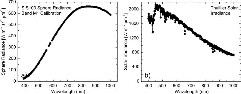
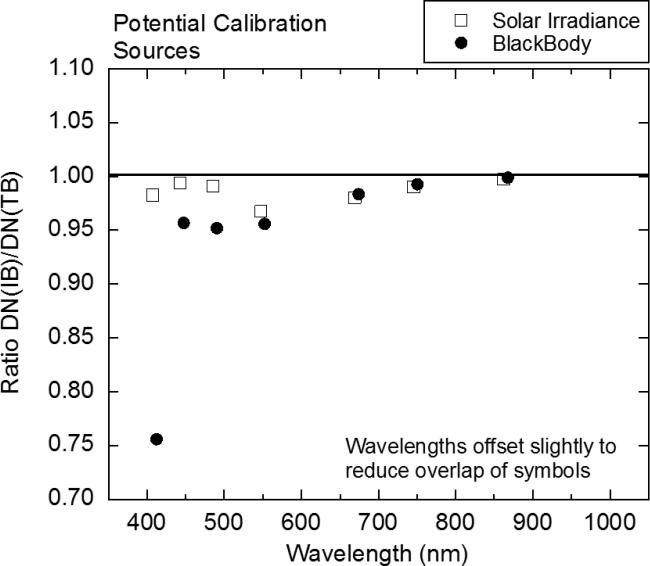
For the VIIRS bands in the visible and near infrared, the fundamental on-orbit measurement is reflectance, which is the ratio of the up-welling Earth radiance to the radiance from an on-board diffuser irradiated by the Sun. For measurements of radiance, the fundamental measurement is the ratio of the up-welling Earth radiance to the radiance of the calibration source. Instruments are calibrated in the laboratory for spectral radiance responsivity pre-launch against lamp-illuminated integrating sphere sources that have spectral distributions approximating a blackbody distribution within a range of temperatures from approximately 2700 K to 3100 K. The SIS100 radiance spectrum used in the historical radiance responsivity calibration of VIIRS is shown in Fig. 19a. Figure 19b shows the solar irradiance spectrum from the measurements of Thuillier et al. (ref. 17) used in VIIRS reflectance measurements. Figure 20 shows the IB to TB ratios calculated for VIIRS bands M1 through M7 for the two spectra shown in Fig. 19. The SpMA-based RSR was used for the IB and TB calculations. The effect of the red leak in the band M1 OOB combined with the red-rich SIS spectrum create a ratio of 0.76 for the 410 nm band in Fig. 20.
Figure 19.
Comparison of a laboratory and an on-orbit source .spectrum.
a) SIS100 radiance spectrum used in the laboratory to calibrate SNPP VIIRS band M1.
b) Solar irradiance spectrum from the Thuillier et al. (ref. 17) solar model.
Note the marked difference in their respective spectral distributions.
Figure 20.
The In-Band to Total-Band ratios (IB/TB) for bands M1 through M7 for a source with a solar distribution and a source with a 2856 K distribution. These are the errors arising from the Out-of-Band responses in the bands. The source spectra are shown in Fig. 19.
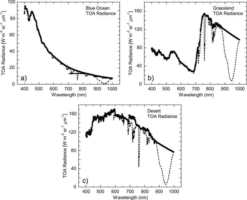
Depending on the approach, either the solar spectral irradiance or the lamp–illuminated SIS radiance may be the reference source spectral distribution. Neither of these spectral distributions approximates the spectral distributions of Earth scenes viewed on-orbit. Extending the discussion to consideration of Earth scenes, Figure 21 shows nominal on-orbit at-sensor radiance distributions for a blue ocean scene, a grassland scene, and a desert scene with and without trace gas absorption (ref. 18). The symbols give the radiances without effects of atmospheric trace gas absorption; the dashed lines include atmospheric absorption based on the nominal atmospheric absorption described in the reference. They provide reasonable first-order estimates for the range of at-sensor spectral radiance distributions to be measured on-orbit by SNPP VIIRS.
Figure 21.
Three nominal Top-of-the-Atmosphere (TOA) radiance spectra (ref. 18). The symbols give the model TOA radiances without trace gas absorption. The dashed lines give the radiances with trace gas absorption included. See the reference for details on the derivation of the spectra.
a) TOA radiances over a blue ocean.
b) TOA radiances over a grassland.
c) TOA radiances over a desert.
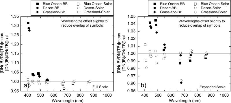
Figure 22 shows the ratios of the IB to TB responses for the three Earth scenes in Fig. 21 relative to those for a solar calibration spectrum and a 2856 K blackbody spectrum. SpMA-based RSR's were again used for the calculations. Results in Fig. 22 are presented as the ratio of the IB to TB measurement divided by the ratio of the IB to TB calibration:
| (14) |
where meas is the on-orbit measured spectrum (from Fig. 21) and cal is the calibration spectrum (from Fig. 19). Here the measured spectra from Fig. 21 are without trace gas absorption. Figure 22 shows the errors due to out-of-band response from using calibration sources with spectral distributions that are different from the at-sensor radiance spectra on-orbit. In general, using a solar calibration source distribution creates residual out-of-band errors equal to or smaller than a blackbody calibration distribution. The error from the red leak in the band M1 Out-of-Band combined with the red-rich blackbody source spectrum is particularly prominent in Fig. 22a. However, using the solar diffuser as the on-orbit calibration source, out-of-band errors for the 3 scenes examined are less than the reflectance calibration requirement of 2 %.
Figure 22.
IB/TB ratios for three Earth scenes relative to a solar calibration spectrum (open symbols) and a 2856 K blackbody spectrum (closed symbols). The ratios show the errors arising from the use of calibration spectra that are different from the spectra measured on orbit.
a) Full Scale.
b) Expanded scale.
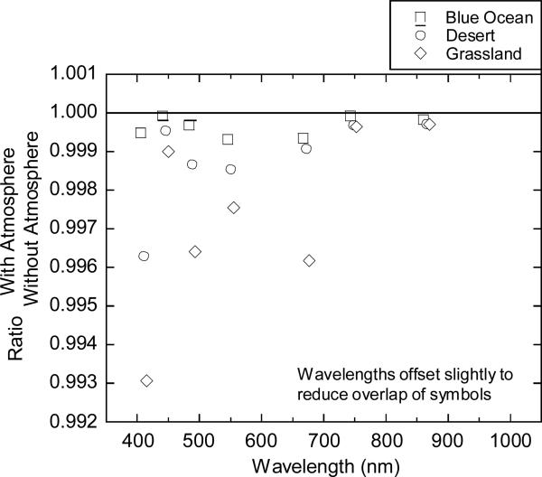
The VIIRS sensor bands have been chosen to view Earth-leaving radiances in atmospheric absorption windows, that is, in spectral regions where there is little absorption from trace gases. As a result, trace gas absorption mainly impacts the OOB measurement and uncertainties in the at-sensor spectral distribution from these absorptions are relatively small. Figure 23 shows the ratio in the calculated OOB error, both with and without absorbing gases in the atmospheric path. The additional error from trace gas absorption is as large as 0.7 % for measurements of grasslands at 410 nm. The maximum error for a desert scene is 0.4 %, also for band M1. The blue ocean scene is not sensitive to the atmospheric absorption in this example, with additional errors less than 0.1 % for all 7 bands.
Figure 23.
Effect of trace gas absorption on the measurements (ratio of with absorption to without). These are the errors due to trace gas absorption.
10.3. Ocean Color Example
Science requirements are strictest for measurements of ocean color, requiring an on-orbit radiance responsivity uncertainty of 0.5 %. One of the advantages of the SIRCUS ASR calibration is that any source distribution can be used as a proxy calibration source in Eq. 11 to develop a band-averaged radiance (SIRCUS) and band-averaged calibration coefficients RBA (SIRCUS) from Eq. 6. This is a user-defined spectral distribution (n); there is no uncertainty in the distribution. DNs are calculated from the summed product of the ASR and the user-defined calibration source distribution.
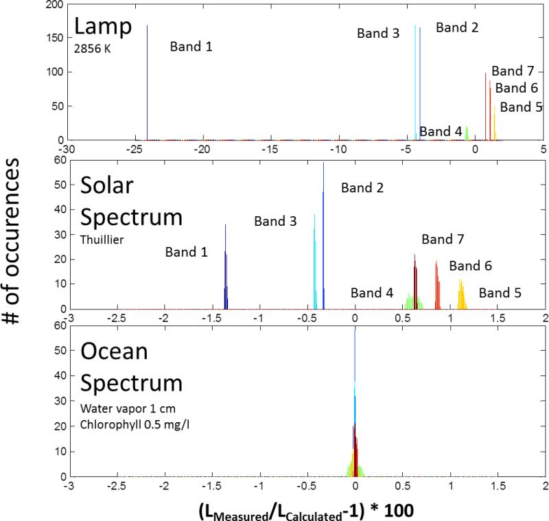
To evaluate the impact of finite OOB response from VIIRS bands, a matrix of at-sensor radiances (nadir view) was developed using MODTRAN (ref. 19) for a range of column water vapor concentrations (0 cm to 5 cm) and near-surface phytoplankton chlorophyll-a concentrations (0.05 mg/l to 3 mg/l) covering the range of values expected on-orbit. A standard marine aerosol, ozone at 300 Dobson Unit (DU), and a standard pressure were selected and not varied during the simulations. A set of 275 at-sensor radiances with differing atmospheric and oceanic radiometric properties was calculated for SNPP VIIRS focal plane detector 8 and bands M1 through M7. Results for 3 different calibration source spectral distributions were compared with ‘true’ radiances and histograms of out-of-band biases were generated.
In addition to the typical calibration sources, an incandescent lamp operating at 2856 K and a solar irradiance spectrum (ref. 17), a proxy calibration source spectrum consisting of the modeled at-sensor radiance for a water-leaving radiance spectrum with a near-surface phytoplankton chlorophyll-a concentration of 0.5 mg/l and a column water vapor concentration of 1 cm was used in the simulations.
Results of the simulations are shown in Fig. 24; the biases arising from OOB response are clearly shown for each calibration source. Each band shows a static bias and a width resulting from the different modeled at-sensor radiance distributions. It is noteworthy that using a nominal ocean/atmosphere calibration source spectral distribution, biases in VIIRS bands are essentially reduced to 0, with the distribution widths of all channels negligible with the exception of Band M4, which has a width < ± 0.05 %.
Figure 24.
Histograms of out-of-band measurement biases arising from different VIIRS calibration sources, shown in bold type on the top left hand side of each graph. A total of 275 spectra with different atmospheric and oceanic properties were used to develop the histograms.
Including any information about atmospheric absorption will reduce these residual errors further. Counting the medium resolution and imaging bands, there are a total of 10 visible and near-infrared bands on VIIRS and some a priori knowledge of the spectral distributions of Earth-reflected radiation. This information can be used to develop a nominal Earth at-sensor spectral distribution for each pixel and from there calculate band responsivities for that distribution. With even a simplistic algorithm, allowing flexibility in the distribution of a calibration source, the residual OOB errors may be reduced to a negligible level where OOB biases would not impact the SIRCUS-based radiometric uncertainties propagated to orbit.
11. CONCLUDING REMARKS
The traditional broadband source-based calibration of SNPP VIIRS is compared with the laser-based SIRCUS calibration of the sensor. For the radiance calibration coefficients (responsivities), the traditional coefficients average 2.2 % higher than SIRCUS (± 1.7 %, k = 1). The estimated uncertainty for the traditional method is 3 % while the uncertainty budget for SIRCUS is 0.56 % (k = 2); and the calibration coefficients agree within the combined uncertainties for the two methods. For the center wavelengths of the central peaks of the bands, the traditional values average 0.06 nm lower than SIRCUS (± 0.14 nm, k = 1), again within the combined uncertainties for the two methods.
The radiance uncertainty for the SIRCUS measurements of SNPP VIIRS is more than a factor 10 improved over the traditional method. In addition, the 3 % uncertainty for the traditionally measured responsivities represents the state-of-the-art for that method. An uncertainty analysis has shown the potential to reduce the SIRCUS-based expanded (k = 2) calibration uncertainty from 0.56 % to less than 0.2 %. The SIRCUS wavelength uncertainty is more than a factor of 5 improved over the traditional method.
The VIIRS instrument experienced crosstalk between the bands. Since the spectral response measurements for the traditional method illuminate a single band at a time, crosstalk in the derived RSRs is minimal and an extensive set of additional measurements were required to estimate the magnitude of this crosstalk. The SIRCUS technique floods the entire VIIRS focal plane for each laser wavelength as the Earth radiance scenes do on-orbit, and crosstalk is evident in the derived RSRs. The SIRCUS measurements of the crosstalk artifact confirmed that the magnitude of the artifact is small, and it has relieved concerns of the ocean color community over the potential impact of large optical cross-talk on VIIRS data products.
With respect to determining detector-to-detector responsivity differences within individual bands, the measurement of all detectors simultaneously by SIRCUS provides an improved characterization over the traditional method, which requires multiple measurements per band with repositioning of the test apparatus between them. The SIRCUS-determined detector-to-detector differences agree well with the effects seen on orbit.
The reduced uncertainties in the laboratory calibration of Earth-observing satellite instruments using SIRCUS will require additional improvements to on-orbit uncertainties to be effective. These include a reduction in the uncertainty of the transfer of the laboratory calibration to orbit as well as a minimization of errors due to OOB response for varying Earth scenes on orbit. Suggestions for both of these effects were discussed. The characterization of long-term instrument responsivity changes can be addressed by monthly measurements of the Moon (ref. 15) while the transfer-to-orbit uncertainty component may be based on measurements of the absolute lunar irradiance (ref. 16). With the resolution of these effects it may be possible to meet the calibration requirements for future instruments listed in the Decadal Survey (ref. 8), possibly including the proposed CLARREO mission.
Figure 5.
Comparison of RSRs from the SpMA and SIRCUS for VIIRS band M2, detector 8. This comparison shows differences (SpMA from SIRCUS) at the SpMA wavelengths. The SIRCUS ASRs have been normalized to unity and interpolated to the SpMA wavelengths. Since SIRCUS provides a greater number of measurements per unit wavelength, the interpolation has removed details from the set of SIRCUS RSRs.
a) SIRCUS and SpMA RSRs.
b) Response Differences (SpMA from SIRCUS). The scale for the differences is given at the right-hand ordinate. The units for the differences are the same as those for the responses, themselves. An outline of the SIRCUS RSR is provided as a visual reference for the locations of the band edges.
Figure 6.
Comparison of RSRs from the SpMA and SIRCUS for VIIRS band M3, detector 8. This comparison shows differences (SpMA from SIRCUS) at the SpMA wavelengths. The SIRCUS ASRs have been normalized to unity and interpolated to the SpMA wavelengths. Since SIRCUS provides a greater number of measurements per unit wavelength, the interpolation has removed details from the set of SIRCUS RSRs.
a) SIRCUS and SpMA RSRs.
b) Response Differences (SpMA from SIRCUS). The scale for the differences is given at the right-hand ordinate. The units for the differences are the same as those for the responses, themselves. An outline of the SIRCUS RSR is provided as a visual reference for the locations of the band edges.
Figure 7.
Comparison of RSRs from the SpMA and SIRCUS for VIIRS band M4, detector 8. This comparison shows differences (SpMA from SIRCUS) at the SpMA wavelengths. The SIRCUS ASRs have been normalized to unity and interpolated to the SpMA wavelengths. Since SIRCUS provides a greater number of measurements per unit wavelength, the interpolation has removed details from the set of SIRCUS RSRs.
a) SIRCUS and SpMA RSRs.
b) Response Differences (SpMA from SIRCUS). The scale for the differences is given at the right-hand ordinate. The units for the differences are the same as those for the responses, themselves. An outline of the SIRCUS RSR is provided as a visual reference for the locations of the band edges.
Figure 8.
Comparison of RSRs from the SpMA and SIRCUS for VIIRS band M5, detector 8. This comparison shows differences (SpMA from SIRCUS) at the SpMA wavelengths. The SIRCUS ASRs have been normalized to unity and interpolated to the SpMA wavelengths. Since SIRCUS provides a greater number of measurements per unit wavelength, the interpolation has removed details from the set of SIRCUS RSRs.
a) SIRCUS and SpMA RSRs.
b) Response Differences (SpMA from SIRCUS). The scale for the differences is given at the right-hand ordinate. The units for the differences are the same as those for the responses, themselves. An outline of the SIRCUS RSR is provided as a visual reference for the locations of the band edges.
Figure 9.
Comparison of RSRs from the SpMA and SIRCUS for VIIRS band M6, detector 8. This comparison shows differences (SpMA from SIRCUS) at the SpMA wavelengths. The SIRCUS ASRs have been normalized to unity and interpolated to the SpMA wavelengths. Since SIRCUS provides a greater number of measurements per unit wavelength, the interpolation has removed details from the set of SIRCUS RSRs.
a) SIRCUS and SpMA RSRs.
b) Response Differences (SpMA from SIRCUS). The scale for the differences is given at the right-hand ordinate. The units for the differences are the same as those for the responses, themselves. An outline of the SIRCUS RSR is provided as a visual reference for the locations of the band edges.
ACKNOWLDGEMENTS
We would like to thank members of Ball Aerospace & Technologies Corporation, Raytheon Space and Airborne Systems, and Northrup Grumman Electronic Systems who contributed greatly to the success of the measurements.
REFERENCES
- 1.Schueler C, Clement JE, Darnton L, DeLuccia F, Scalione T, Swenson H. VIIRS sensor performance. International Geosciences and Remote Sensing Symposium (IGSRSS) Proceedings. 2003 Jul; [Google Scholar]
- 2.Murphy R, Barnes W, Lyapustin A, Privette J, Welsch C, DeLuccia F, Swenson H, Schueler C, Ardanuy P, Kealy P. Using VIIRS to provide data continuity with MODIS. International Geosciences and Remote Sensing Symposium (IGARSS) Proceedings. 2001 Jul; [Google Scholar]
- 3.Schueler C, Clement JE, Ardanuy P, Welsch C, DeLuccia F, Swenson H. NPOESS VIIRS sensor design overview. Proc. SPIE. 2002;4483:11–23. [Google Scholar]
- 4.Butler JJ, Johnson BC, Brown SW, Saunders RD, Biggar SF, Zalweski EF, Markham BL, Gracey PN, Young JB, Barnes RA. Radiometric measurement comparison on the integrating sphere source used to calibrate the Moderate Imaging Spectroradiometer (MODIS) and the Landsat 7 Enhanced Thematic Mapper (ETM+) J. Res. Natl. Inst. Stand. Technol. 2003;108:199–228. doi: 10.6028/jres.108.020. [DOI] [PMC free article] [PubMed] [Google Scholar]
- 5.Brown SW, Eppeldauer GP, Lykke KR. Facility for spectral irradiance and radiance responsivity calibrations using uniform sources. Appl. Opt. 2006;45:8218–8237. doi: 10.1364/ao.45.008218. [DOI] [PubMed] [Google Scholar]
- 6.Scalione T, DeLuccia F, Cymerman J, Johnson E, McCarthy JK, Olejniczak D. VIIRS Initial performance Verification. International Geosciences and Remote Sensing Symposium (IGSRSS) Proceedings. 2005 Jul; [Google Scholar]
- 7.Yoon HW, Gibson CE, Eppeldauer GP, Smith AW, Brown SW, Lykke KR. Thermodynamic radiation thermometry using radiometers calibrated for radiance responsivity. Int. J. Thermophys. 2011;32:2217–2229. [Google Scholar]
- 8.Space Studies Board, National Research Council . Earth Science and Imperatives from Space: National Imperatives for the Next Decade and Beyond. National Academies Press; Washington, DC: 2007. [Google Scholar]
- 9.Pre-Aerosol, Clouds, and ocean Ecosystem (PACE) Mission Science Definition Team Report. :90. http://dsm.gsfc.nasa.gov/pace_documentation/PACE_SDT_Report_final.pdf.
- 10.Thome K, Gubbels T, Barnes R. Preliminary error budget for the reflected solar instrument for the Climate Absolute Radiance and Refractivity Observatory. Proc. SPIE. 2011;8513:8513R. [Google Scholar]
- 11.Butler JJ, Johnson BC, Rice JP, Brown SW, Barnes RA. Validation of radiometric standards for laboratory calibration of reflected-solar Earth observing satellite instruments. Proc. SPIE. 2007;6677:667707. [Google Scholar]
- 12.Franz BA, Bailey SW, Werdell PJ, McClain CR. Sensor-independent approach to the vicarious calibration of satellite ocean color radiometry. Appl. Opt. 2007;46:5068–5082. doi: 10.1364/ao.46.005068. [DOI] [PubMed] [Google Scholar]
- 13.Shaw Ping-Shine. NIST; personal communication. [Google Scholar]
- 14.Barnes RA, Eplee RE, Jr., Biggar SF, Thome KJ, Slater PN, Holmes AW. SeaWiFS transfer-to-orbit experiment. Appl. Opt. 2000;39:5620–5631. doi: 10.1364/ao.39.005620. [DOI] [PubMed] [Google Scholar]
- 15.Barnes RA, Eplee RE, Jr., Patt FS, Kieffer HH, Stone TC, Meister G, Butler JJ, McClain CR. Comparison of SeaWiFS measurements of the Moon with the USGS lunar model. Appl. Opt. 2004;43:5838–5842. doi: 10.1364/ao.43.005838. [DOI] [PubMed] [Google Scholar]
- 16.Cramer CE, Lykke KR, Woodward JT, Smith AW. Precise measurement of lunar spectral irradiance at visible wavelengths. J. Res. NIST. 2013;108:396–402. doi: 10.6028/jres.118.020. [DOI] [PMC free article] [PubMed] [Google Scholar]
- 17.Thuillier G, Hersé M, Labs D, Foujols T, Peetermans W, Gillotay D, Simon PC, Mandel H. The solar spectral irradiance from 200 to 2400 nm as measured by the Solspec spectrometer from the Atlas and Eureca missions. Solar Phys. 2003;214:1–22. [Google Scholar]
- 18.Barnes RA, Butler JJ. Modeling spectral effects in Earth-observing satellite instruments. Proc. SPIE. 2007;6744:64771K. [Google Scholar]
- 19.Berk A, Bernstein LS, Robertson DC. Tech. Report GL-TR-90-0122. Phillips Laboratory; Hanscom AFB, Ma.: 1989. MODTRAN: A Moderate Resolution Model for LOWTRAN7. [Google Scholar]


