Abstract.
Fluorescence microscopy is commonly used to investigate disease progression in biological tissues. Biological tissues, however, are strongly scattering in the visible wavelengths, limiting the application of fluorescence microscopy to superficial () regions. Optical clearing, which involves incubation of the tissue in a chemical bath, reduces the optical scattering in tissue, resulting in increased tissue transparency and optical imaging depth. The goal of this study was to determine the time- and wavelength-resolved dynamics of the optical scattering properties of rodent brain after optical clearing with FocusClear™. Light transmittance and reflectance of 1-mm mouse brain sections were measured using an integrating sphere before and after optical clearing and the inverse adding doubling algorithm used to determine tissue optical scattering. The degree of optical clearing was quantified by calculating the optical clearing potential (OCP), and the effects of differing OCP were demonstrated using the optical histology method, which combines tissue optical clearing with optical imaging to visualize the microvasculature. We observed increased tissue transparency with longer optical clearing time and an analogous increase in OCP. Furthermore, OCP did not vary substantially between 400 and 1000 nm for increasing optical clearing durations, suggesting that optical histology can improve ex vivo visualization of several fluorescent probes.
Keywords: optical clearing, tissue optics, optical properties, scattering
1. Introduction
Researchers commonly use fluorescence microscopy to investigate and study disease progression in biological tissues. Prior to imaging, researchers may incubate the tissue with exogenous biomarkers conjugated with fluorescent probes that bind to specific sites of interest, enabling precise localization and visualization of fine structural features. Since many biological tissues strongly scatter visible wavelengths, fluorescence microscopy applications often remain limited to superficial ( in depth) regions.
Recently, several research groups have developed protocols involving the use of chemical agents to reduce the degree of optical scattering in turbid tissues.1,2 These reports describe the use of various optical clearing agents, including glycerol,3 dimethylsulfoxide (DMSO),4 benzyl alcohol benzyl benzoate,5 tetrahydrafuran,6 FocusClear,7 Scale,8 CLARITY,9 and 3DISCO.10 In addition to chemical optical clearing, both the CLARITY and 3DISCO protocols involve complex tissue processing; CLARITY requires electrophoretic optical clearing to remove highly scattering lipids, while 3DISCO requires several tissue dehydration steps with toxic and flammable chemicals, which necessitate special chemical safety considerations. The result is that both techniques are more challenging to implement than simply immersing the tissue in an optical clearing agent. We recently described a method that we call optical histology,11,12 which involves applying optical clearing using FocusClear to thick () tissue sections and subsequent imaging with confocal fluorescence microscopy. With optical histology, we demonstrated high-resolution visualization of fluorescent structures up to depths of 500 to within each section.
The efficacy of optical clearing depends on multiple factors including tissue type and selected chemical agent. In general, researchers desire a substantial increase in tissue transparency, which is associated with a decrease in optical scattering. Previous studies related to optical clearing2,13 describe the use of measurements of optical transmittance of native and cleared tissues to assess changes in tissue optical properties after optical clearing. However, since transmittance depends on optical scattering, tissue thickness, and (to a lesser extent) optical absorption, transmittance alone does not enable quantification of optical scattering. Hence, additional measurements are required to fully characterize the optical clearing process.
Optical properties in ex vivo thick tissue can be quantified using the integrating sphere technique coupled with an appropriate model of light propagation.14 Measurements can involve either a single integrating sphere, which enables sequential measurement of diffuse reflectance and total transmittance, or a double integrating sphere,15 which consists of two adjoined integrating spheres that enable simultaneous measurement of diffuse reflectance and total transmittance. From measurements of total transmittance, diffuse reflectance, and sample thickness one can estimate the optical scattering and absorption of the tissue using a model based approach,16 such as diffusion theory,17 Monte Carlo simulation,18 or the inverse adding doubling (IAD) algorithm.19 We previously used an integrating sphere and the IAD algorithm to evaluate the efficacy of various optical clearing agents19 and introduced the metric of optical clearing potential (OCP). OCP is a ratio of the reduced optical scattering coefficient before optical clearing to the value after clearing, and quantitatively describes the change in optical scattering that occurs due to optical clearing. In this paper, we describe the use of integrating sphere-mediated optical spectroscopy and the IAD algorithm to quantify the reduced optical scattering coefficient, and to determine the time-resolved change in optical scattering associated with FocusClear-mediated optical clearing of ex vivo mouse brain samples.
2. Materials/Methods
2.1. Tissue Preparation
We used a tissue preparation method described previously.11 Briefly, we harvested the brain from male adult C3H mice (25 to 30 g). Immediately after sacrifice, we performed cardiac perfusion of 5 mL saline followed by 5 mL of 4% paraformaldehyde. We then harvested the brain and placed it in 4% paraformaldehyde for a minimum of three days. After fixation, we sliced the brain into coronal slices of thickness, for a total of 19 slices.
2.2. Tissue Holder
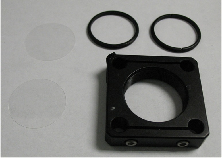
We placed each slice into a tissue holder consisting of a 30-mm SM1 threaded optic holder (CP08, Thor Labs, New Jersey), two 25-mm circular cover glasses (Fisherbrand Cover Glass No. 1, Fisher Scientific, Waltham, Massachusetts), and two 30-mm SM1 threaded retaining rings (SM30RR, Thor Labs, New Jersey; Fig. 1). We inserted the slice between the circular cover glasses and used the retaining rings to hold it in place. With this apparatus, the tissue remained fixed in position and its thickness was maintained during the optical measurements. We measured the sample thickness more precisely by measuring the thickness of the entire apparatus (with slice in place) and subtracting the measured thickness of the apparatus alone (i.e., without the slice).
Fig. 1.
Components of tissue holder, which is used to immobilize the tissue and keep the tissue thickness uniform during imaging. The tissue holder consists of a 30-mm threaded optic holder, two 25-mm circular glass slides, and two 30-mm threaded retaining rings used to evenly compress and sandwich the glass slides together against the tissue.
2.3. Optical Spectroscopy
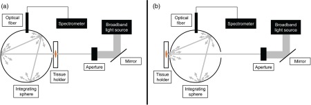
We used an integrating sphere setup to acquire optical transmittance and reflectance data from the brain slices both before and after optical clearing (Fig. 2). The setup consisted of an integrating sphere (Labsphere Inc., North Sutton, New Hampshire), a broadband halogen light source whose output was collimated to a diameter of 4 mm, and spectrometer (Prime-X, B&W Tek, Newark, Delaware). The range of the spectrometer was 400 to 1000 nm, with a spectral resolution of 4.8 nm (FWHM). We used a custom-written LabVIEW program (National Instruments, Austin, Texas) to communicate with the spectrometer, and a 99% reflectance standard (Spectralon, LabSphere Inc.) to calibrate the reflectance measurements.
Fig. 2.
Schematic of integrating sphere setup for (a) transmittance measurements and (b) reflectance measurements.
2.4. Optical Histology
The optical histology method was performed as previously described.11,12 Briefly, this method first involved cardiac perfusion of the lipophilic fluorescent dye DiI to label the mouse microvasculature, followed by tissue harvest and preparation similar to the procedure previously described. All procedures were approved by the Institutional Animal Care and Use Committee at University of California, Irvine. Slices with thickness of 1 mm were optically cleared with FocusClear (CelExplorer Labs, Hsinchu, Taiwan), a DMSO-based optical clearing agent. We then imaged the DiI-labeled microvessels with a commercial confocal fluorescence microscope (LSM 510 META, Zeiss, Oberkochen, Germany) using a 543 nm laser for excitation of DiI fluorescence and air objective.
Here we present the microscopy data as depth-encoded maximum intensity projection maps (MIP). MIP images are constructed by determining, for each lateral position, the maximum intensity over all depths from the image slices in a confocal microscopy image stack and projecting these pixels onto a two-dimensional (2-D) image. Each pixel is assigned a color corresponding to the originating slice in the image stack resulting in a depth-encoded MIP map that gives three-dimensional information in a 2-D image.
2.5. Experimental Procedure
The procedures used to perform integrating sphere measurements to quantify tissue optical properties are well documented.18–21 We first collected a standard reflectance measurement, which consisted of no sample in the beam path and the 99% diffuse reflectance standard at the reflectance port. We then mounted a brain slice in the tissue holder and measured the thickness of the glass-tissue preparation with a micrometer (Mitutoyo Corp., Kawasaki, Japan). We then placed the tissue holder at either the transmittance or reflectance port of the sphere and measured the corresponding transmitted or remitted light, respectively. We carefully positioned the tissue holder to achieve uniform illumination of the slice. To account for potential heterogeneities in the optical properties of each slice, we collected measurements from three locations of each slice. After we collected measurements from each slice, we again performed the standard reflectance measurement to account for the drift in the power of the optical excitation. We collected calibration measurements at every sample measurement time point to correct for any long-term drift from the light source. Under these conditions, measurement drift was at each measurement time point. Similar to our previously published study,11 we immersed each slice in 1 mL of FocusClear, allowing exchange of tissue water with FocusClear. We collected data during four periods of increasing optical clearing time: 1 h (), 3 h (), 6 h (), and 24 h () in order to assess the effects of increasing optical clearing duration.
2.6. Data Processing
Similar to our previous work,22 we analyzed the wavelength-dependent reflectance and transmittance data using the IAD algorithm described by Prahl et al.19 IAD enables estimation of tissue optical properties based on measurements of diffuse reflectance, total transmittance, and sample thickness. At each measurement location and time point, we applied the IAD algorithm to calculate the reduced scattering coefficient () at specific wavelengths over the spectral range of 400 to 1000 nm. We then determined the average based on the individual wavelength-resolved values of calculated at each of the three measurement locations and at each time point to achieve . We then calculated the OCP22 for each slice, defined as
Finally, at each measurement wavelength and time point, we calculated the mean OCP and standard deviation of the mean.
3. Results
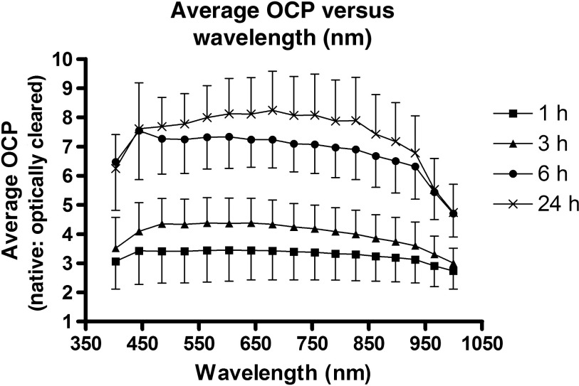
Figure 3 is a time course set of images of different brain slices optically cleared with FocusClear for different optical clearing incubation times. Under visual inspection, the tissues appeared to become more transparent with longer optical clearing time, which was an expected result. Table 1 summarizes the baseline values at the interrogated wavelengths, which are averaged over all samples and all time points. We observed an expected monotonic decrease in with an increase in wavelength. Tissue slice thickness before optical clearing ranged from 0.7 to 1.4 mm for the different optical clearing time points. Figure 4 is a plot of OCP versus wavelength for each of the different optical clearing times. At each wavelength, OCP increased with increasing optical clearing time, though we observed that the amount of OCP increase was lower between 6 and 24 h of optical clearing time than between 3 and 6 h optical clearing times. However, for a given optical clearing time, the OCP spectrum is relatively flat over the visible-NIR wavelength range.
Fig. 3.
Color images of representative brain slices (a) before and (b–e) after optical clearing with FocusClear for (b) 1 h, (c) 3 h, (d) 6 h, and (e) 24 h. .
Table 1.
Baseline reduced optical scattering coefficient values of the mouse brain slices used in this study. SD = standard deviation.
| Wavelength (nm) | Mean (SD) () |
|---|---|
| 403 | 2.33 (0.51) |
| 444 | 2.71 (0.60) |
| 485 | 2.62 (0.60) |
| 525 | 2.40 (0.56) |
| 565 | 2.22 (0.52) |
| 604 | 2.06 (0.49) |
| 642 | 1.93 (0.46) |
| 680 | 1.80 (0.43) |
| 718 | 1.68 (0.40) |
| 755 | 1.58 (0.38) |
| 791 | 1.49 (0.36) |
| 827 | 1.42 (0.34) |
| 863 | 1.35 (0.32) |
| 898 | 1.29 (0.31) |
| 932 | 1.23 (0.29) |
| 966 | 1.21 (0.28) |
| 999 | 1.19 (0.28) |
Fig. 4.
Line plot of average optical clearing potential versus wavelength for all time points (1, 3, 6, and 24 h).
4. Discussion
We immersed samples in FocusClear for different periods of time. We observed that an increase in immersion time induced an increase in sample transparency (Fig. 3). We quantified this increased transparency as an increase in mean OCP at all wavelengths between 400 and 1000 nm (Fig. 4).
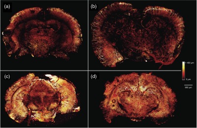
To illustrate the effects of different levels of OCP achieved, we used methodology described previously,11 to image four 1-mm thick coronal slices of mouse brain with microvasculature labeled with DiI (Fig. 5). We optically cleared brain slices with the same four optical clearing times used in the integrating sphere measurements. An immersion time did not further increase the depth that vessels could be visualized, as we visualized vessels at similar tissue depths in the 3, 6, and 24 h time points. However, there was a clear effect on the microvascular density that could be visualized at all depths, as the brain slices cleared for 6 and 24 h showed a higher density of vasculature as compared to the brain slices cleared for 1 and 3 h. This is consistent with the trends seen in OCP (Fig. 4), as OCP increased between 1 and 3 h of optical clearing, increased further between 3 and 6 h, and increased slightly between 6 and 24 h of optical clearing. Interestingly, the mean OCP did not exhibit a dependence on wavelength (Fig. 4). The generic shape of an optical scattering spectrum is23
where is the scattering amplitude and is a term that takes into account the scatterer size. The relative independence of OCP on optical wavelength (Fig. 4) suggests that FocusClear induces a reduction only in and no significant change in the distribution of scatterer sizes. Based on this assessment, we propose that FocusClear reduces the scattering properties of the fixed brain sections due primarily to improvement in refractive index matching between white and gray matter in the brain as opposed to alterations in tissue structure as demonstrated previously in collagenous tissues.24
Fig. 5.
Maximum intensity projection (MIP) maps of tissue microvasculature in 1-mm brain slices optically cleared for (a) 1 h, (b) 3 h, (c) 6 h, and (d) 24 h showing the increased density of vasculature that can be visualized with increasing optical clearing time. MIP images are constructed by determining the maximum intensity pixel at each pixel location from all of the image slices in a confocal microscopy image stack and projecting these pixels onto a two-dimensional (2-D) image. Each pixel is assigned a color corresponding to the originating slice in the image stack resulting in a depth-encoded MIP map that gives three-dimensional information in a 2-D image.
Furthermore, since FocusClear is associated with an OCP that is relatively constant with wavelength, we propose that optical histology with FocusClear is conducive to optical imaging of a wide range of fluorescent molecular probes that emit over the visible and near-infrared wavelength range. Hence, with optical histology using FocusClear, researchers have flexibility in selection of an exogenous probe that best matches their specific application.
The exact mechanism by which FocusClear achieves enhanced optical transparency of brain tissue is unclear. In optical clearing of skin with glycerol, a factor contributing to reduced scattering is the matching of refractive index between collagen () and glycerol ().25 Interestingly, the refractive index of FocusClear () is relatively high compared with native brain tissues ( to 1.40).26 Hence, alternate factors may play a contributing or major role in the optical clearing properties of FocusClear on mouse brain—further study is warranted, as a complete understanding of the mechanism of action of clearing will lead to more rational optimization of protocols based on FocusClear.
In summary, our measurements suggest that optical clearing of fixed brain slices with FocusClear achieves a substantial increase in OCP at immersion times as short as 6 h. Furthermore, because the wavelength dependence of the OCP is flat over the range from 400 to 1000 nm, these results suggest that this optical histology approach can improve ex vivo visualization of a wide range of fluorescent molecular probes.
Acknowledgments
This work was supported in part by the Arnold and Mabel Beckman Foundation, the National Institutes of Health grant award R01 HD065536, and the National Institutes of Health Laser Microbeam and Medical Program (LAMMP, a P41 Technology Research Resource, grant number EB015890).
Biographies
Austin J. Moy is currently a postdoctoral fellow in the Department of Biomedical Engineering at The University of Texas at Austin. He received his PhD in biomedical engineering from the University of California, Irvine.
Bernard V. Capulong received his BS degree in biomedical engineering from the University of California, Irvine.
Rolf B. Saager is currently a project scientist at the Beckman Laser Institute, University of California, Irvine. He received his PhD in optics at the University of Rochester.
Matthew P. Wiersma received his BS degree in biomedical engineering from the University of California, Irvine.
Patrick C. Lo received his BS degree in biomedical engineering from the University of California, Irvine. He is currently in the MS program at the University of Southern California and maintains a junior specialist appointment at the University of California, Irvine.
Anthony J. Durkin is currently an associate professor in the Departments of Biomedical Engineering and Surgery at the University of California, Irvine, with a primary appointment in the Beckman Laser Institute. He received his PhD in biomedical engineering from The University of Texas at Austin.
Bernard Choi is currently an associate professor in the Departments of Biomedical Engineering and Surgery at the University of California, Irvine, with appointments in the Beckman Laser Institute and the Edwards Lifescience Center for Advanced Cardiovascular Technology. He received his PhD in biomedical engineering from The University of Texas at Austin.
References
- 1.Tuchin V., “Optical clearing of tissues and blood using the immersion method,” J. Phys. Appl. Phys. 38(9), 2497–2518 (2005). 10.1088/0022-3727/38/15/001 [DOI] [Google Scholar]
- 2.Vargas G., et al. , “Use of osmotically active agents to alter optical properties of tissue: effects on the detected fluorescence signal measured through skin,” Lasers Surg. Med. 29(3), 213–220 (2001). 10.1002/lsm.1110 [DOI] [PubMed] [Google Scholar]
- 3.Xu X., Wang R. K., “Synergistic effect of hyperosmotic agents of dimethyl sulfoxide and glycerol on optical clearing of gastric tissue studied with near infrared spectroscopy,” Phys. Med. Biol. 49(3), 457–468 (2004). 10.1088/0031-9155/49/3/008 [DOI] [PubMed] [Google Scholar]
- 4.Bui A. K., et al. , “Revisiting optical clearing with dimethyl sulfoxide (DMSO),” Lasers Surg. Med. 41(2), 142–148 (2009) 10.1002/lsm.20742 [DOI] [PMC free article] [PubMed] [Google Scholar]
- 5.Parra S. G., et al. , “Multiphoton microscopy of cleared mouse organs,” J. Biomed. Opt. 15(3), 036017 (2010) 10.1117/1.3454391 [DOI] [PubMed] [Google Scholar]
- 6.Ertürk A., et al. , “Three-dimensional imaging of the unsectioned adult spinal cord to assess axon regeneration and glial responses after injury,” Nat. Med. 18(1), 166–171 (2012). 10.1038/nm.2600 [DOI] [PubMed] [Google Scholar]
- 7.Fu Y. Y., Tang S. C., “Optical clearing facilitates integrated 3D visualization of mouse ileal microstructure and vascular network with high definition,” Microvasc. Res. 80(3), 512–521 (2010). 10.1016/j.mvr.2010.06.003 [DOI] [PubMed] [Google Scholar]
- 8.Hama H., et al. , “Scale: a chemical approach for fluorescence imaging and reconstruction of transparent mouse brain,” Nat. Neurosci. 14, 1481–1488 (2011). 10.1038/nn.2928 [DOI] [PubMed] [Google Scholar]
- 9.Chung K., et al. , “Structural and molecular interrogation of intact biological systems,” Nature 497, 332–337 (2013). 10.1038/nature12107 [DOI] [PMC free article] [PubMed] [Google Scholar]
- 10.Ertürk A., et al. , “Three-dimensional imaging of solvent-cleared organs using 3DISCO,” Nat. Protoc. 7(11), 1983–1995 (2012) 10.1038/nprot.2012.119 [DOI] [PubMed] [Google Scholar]
- 11.Moy A. J., Wiersma M. P., Choi B., “Optical histology: a method to visualize microvasculature in thick tissue sections of mouse brain,” PLoS One 8(1), e53753 (2013). 10.1371/journal.pone.0053753 [DOI] [PMC free article] [PubMed] [Google Scholar]
- 12.Moy A. J., Lo P. C., Choi B., “High-resolution visualization of mouse cardiac microvasculature using optical histology,” Biomed. Opt. Express 5(1), 69–77 (2013). 10.1364/BOE.5.000069 [DOI] [PMC free article] [PubMed] [Google Scholar]
- 13.Rylander C. G., et al. , “Dehydration mechanism of optical clearing in tissue,” J. Biomed. Opt. 11(4), 041117 (2006) 10.1117/1.2343208 [DOI] [PubMed] [Google Scholar]
- 14.Kim A., Wilson B. C., “Measurement of ex vivo and in vivo tissue optical properties: methods and theories,” in Optical-Thermal Response of Laser-Irradiated Tissues, Welch A. J., van Gemert M. J. C., pp. 267–319, Springer, Netherlands: (2011). [Google Scholar]
- 15.Pickering J. W., et al. , “Double-integrating-sphere system for measuring the optical properties of tissue,” Appl. Opt. 32(4), 399–410 (1993). 10.1364/AO.32.000399 [DOI] [PubMed] [Google Scholar]
- 16.Cheong W.-F., Prahl S. A., Welch A. J., “A review of the optical properties of biological tissues,” IEEE J. Quantum Electron. 26(12), 2166–2185 (1990). 10.1109/3.64354 [DOI] [Google Scholar]
- 17.Star W. M., “The relationship between integrating sphere and diffusion theory calculations of fluence rate at the wall of a spherical cavity,” Phys. Med. Biol. 40(1), 1–8 (1995). 10.1088/0031-9155/40/1/001 [DOI] [PubMed] [Google Scholar]
- 18.Simpson C. R., et al. , “Near-infrared optical properties of ex vivo human skin and subcutaneous tissues measured using the Monte Carlo inversion technique,” Phys. Med. Biol. 43(9), 2465–2478 (1998). 10.1088/0031-9155/43/9/003 [DOI] [PubMed] [Google Scholar]
- 19.Prahl S. A., van Gemert M. J., Welch A. J., “Determining the optical properties of turbid media by using the adding-doubling method,” Appl. Opt. 32(4), 559–568 (1993). 10.1364/AO.32.000559 [DOI] [PubMed] [Google Scholar]
- 20.Yuzhakov A. V., et al. , “Optical characteristics of the cornea and sclera and their alterations under the effect of nondestructive laser radiation,” J. Biomed. Opt. 18(5), 058003 (2013). 10.1117/1.JBO.18.5.058003 [DOI] [PubMed] [Google Scholar]
- 21.Honda N., et al. , “Determination of the tumor tissue optical properties during and after photodynamic therapy using inverse Monte Carlo method and double integrating sphere between 350 and 1000 nm,” J. Biomed. Opt. 16(5), 058003 (2011). 10.1117/1.3581111 [DOI] [PubMed] [Google Scholar]
- 22.Choi B., et al. , “Determination of chemical agent optical clearing potential using in vitro human skin,” Lasers Surg. Med. 36(2), 72–75 (2005). 10.1002/lsm.20116 [DOI] [PubMed] [Google Scholar]
- 23.Jacques S. L., “Optical properties of biological tissues: a review,” Phys. Med. Biol. 58(11), R37–R61 (2013). 10.1088/0031-9155/58/11/R37 [DOI] [PubMed] [Google Scholar]
- 24.Yeh A. T., et al. , “Reversible dissociation of collagen in tissues,” J. Invest. Dermatol. 121(6), 1332–1335 (2003). 10.1046/j.1523-1747.2003.12634.x [DOI] [PubMed] [Google Scholar]
- 25.Vargas G., et al. , “Use of an agent to reduce scattering in skin,” Lasers Surg. Med. 24(2), 133–141 (1999). [DOI] [PubMed] [Google Scholar]
- 26.Sun J., et al. , “Refractive index measurement of acute rat brain tissue slices using optical coherence tomography,” Opt. Express 20(2), 1084 (2012). 10.1364/OE.20.001084 [DOI] [PMC free article] [PubMed] [Google Scholar]


