Abstract
Si has been considered as a promising alternative anode for next-generation Li-ion batteries (LIBs) because of its high theoretical energy density, relatively low working potential, and abundance in nature. However, Si anodes exhibit rapid capacity decay and an increase in the internal resistance, which are caused by the large volume changes upon Li insertion and extraction. This unfortunately limits their practical applications. Therefore, managing the total volume change remains a critical challenge for effectively alleviating the mechanical fractures and instability of solid-electrolyte-interphase products. In this regard, we review the recent progress in volume-change-accommodating Si electrodes and investigate their ingenious structures with significant improvements in the battery performance, including size-controlled materials, patterned thin films, porous structures, shape-preserving shell designs, and graphene composites. These representative approaches potentially overcome the large morphologic changes in the volume of Si anodes by securing the strain relaxation and structural integrity in the entire electrode. Finally, we propose perspectives and future challenges to realize the practical application of Si anodes in LIB systems.
Keywords: elastic electrodes, electrode engineering, Si nanostructures, silicon anodes, volume change accommodation
1. Introduction
In the last two decades, Li-ion batteries (LIBs) have occupied the portable-electronics market as a primary power supplier with a higher gravimetric and volumetric capacity than other rechargeable-battery systems (e.g., Ni–Cd, lead–acid, redox-flow, and metal-ion batteries). However, current LIB technologies cannot satisfy the energy and power requirements of a wide range of applications, from portable electronic devices to all-electric vehicles and smart grids.[1] In this regard, battery roadmaps from the Department of Energy (DOE, USA)[2] and the New Energy and Industrial Technology Development Organization (NEDO, Japan)[3] indicate that successful development of progressive LIBs will become a top priority for nations around the world. Hence, there are significant research challenges regarding all kinds of battery components, including cathodes, anodes, current collectors, electrolytes, and separators.
Regarding anodes in particular, substituting graphite with high-capacity alternative materials has been highlighted as a crucial challenge in practice. Although conventional graphite anodes exhibit excellent electrochemical performance, such as a long cycle life, low irreversible capacity loss, and low volumetric expansion (<17 %) during charging and discharging,[4] they cannot satisfy the fast-growing demands for high energy storage owing to their low theoretical capacity of 372 mAh g−1 and the safety problems of Li deposition. Considering these issues, Li alloys have great potential as alternative anodes owing to their high charge density and moderate operation potential compared with Li/Li+.[5] Among these alloys, Si has attracted interest as the most outstanding candidate material for next-generation LIB anodes, exhibiting the following remarkable advantages: 1) extremely high gravimetric (3579 mAh g−1) and volumetric capacities (2190 mAh cm−3) with the fully lithiated alloy state (Li15Si4) at room temperature;[6] 2) a low operation potential (∼370 mV vs. Li/Li+),[7] which is profitable for the implementation of high-power and high-energy cells in accordance with the high theoretical capacity of Si; 3) eco-friendliness, abundance,[8] and inexpensiveness comparable to those of graphite.[5,9] However, despite these merits of Si, its intrinsic drawbacks yield difficult challenges in the practical application of Si anodes. First, alongside its low conductivity (∼10−3 S cm−1)[10] and Li diffusion coefficient (between 10−14 and 10−13 cm2 s−1),[11] Si suffers an extremely large volume variation (∼400 %) during the Li insertion and extraction reactions.[12] The induced stress and strain due to this volume variation cause a severe material collapse and electrical isolation, resulting in a low coulombic efficiency (CE) and rapidly declining capacity.[13] Repeated volume expansion and contraction yields an unstable solid electrolyte interphase (SEI) between the re-exposed Si surface and electrolyte during cycling, which leads to an increase in the internal impedance and a deleterious effect on the electrochemical reactivity due to the accumulation of the insulated SEI products. These extreme volume changes present a crucial challenge for overcoming the failure mechanism of Si anodes and must be addressed in order to secure the stability of the entire electrode and thereby improve the battery performance.
Unlike previous reports regarding the comprehensive engineering of Si anodes to improve the battery performance,[14] this review focuses on the representative strategies for accommodating the volume change of Si anodes, including size-controlled materials and sophisticated structures such as a patterned thin film, porous structure, shape-preserving shell design, and graphene composite (Scheme 1). We summarize the battery-performance improvements and propose perspectives and future challenges for realizing the application of Si anodes in practical LIB systems.
Figure 1.
Thin-film strategies for volume-change-accommodating electrode. a) Relationship between the critical crack spacing (Lcr) in the Si film and critical size of Si patches (L) against interfacial delamination. Plastic localization inside Si patches induces interfacial delamination when L is larger than Lcr which is calculated as 5.1–8.9 μm with 100 nm of thickness.[20] b) Behavior of honeycomb patterns during lithiation/delithiation.[21] c) SEM images of alumina coated patterns before and after 1st lithiation in top view.[22] Reprinted with permission from Refs. [20,22]]. Copyright 2011 Elsevier B.V; Copyright, 2011 John Wiley & Sons, Inc.; Copyright, 2011 John Wiley & Sons, Inc.
Scheme 1.
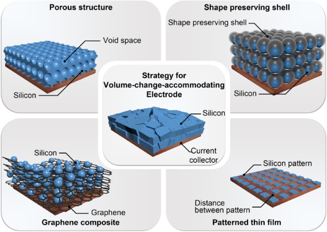
Representative strategies for volume-change-accommodating electrode.
2. Strategy for Designing Volume-Change- Accommodating Electrodes
2.1. Size-Controlled Materials
Generally, researchers agree that moving from bulk to nanoscale engineering is the most effective strategy to significantly impact the electrochemical performance by addressing the intrinsic problems of the Si anode.[14,15] Nanosized Si can successfully relieve a severe lithiation-induced strain and even resist fractures and pulverization when the size is below the critical limits, that is, 150 nm for crystalline Si and >870 nm for amorphous Si.12b,[16] The behavior of nanosized Si during cycling were demonstrated by in situ transmission electron microscopy (TEM) and mathematical modeling.12a Kim et al. investigated the effect of the size of the Si on electrochemical reactions, reporting elastic volume change as the size approached 10 nm.[17] In addition, a high specific surface area between the electrolytes and nanostructured electrodes stimulates the charge transfer across the electrode/electrolyte interface.[18] Furthermore, the rate of Li alloying/dealloying reactions can be improved significantly with nanomaterials having small dimensions, owing to the reduced characteristic time constant (t) in the diffusion, which is given by t=L2D−1 (L: diffusion length, D: diffusion coefficient).[18] These merits enable the nanosized Si not only to help in accommodating severe volume changes with its improved mechanical properties but also to provide improved electrochemical properties. In light of the improved battery performance of the nanosized Si particle,[19] one-dimensional (1D) nanowires and nanotubes have attracted attention for retaining structural integrity and efficient charge transport. For example, Si nanowires that were directly grown on stainless steel exhibited a high battery performance owing to the prior benefits of the nanosize effects and the 1D electronic path of the wire structure.[20] Si nanotubes, which retain suitable voids in the wire structure, can also efficiently accommodate volume changes and provide good electrochemical properties.[21] Thus, reducing the material size and applying it to some kind of structure comprise an essential preliminary approach for increasing the electrochemical properties and handling the large volume change during cycling.
2.2. Patterned Thin Films
In past decades, thin-film electrodes have been studied to elucidate the fundamental properties of Si owing to their simple model for both simulations and experiments, including their mechanical behavior during cycling and their phase evolutions.[19] Regarding the strategies for resolving the volume-change problem, thin-film engineering has played an important role in clarifying the stress evolution of Si anodes during cycling.19e,19f Based on the mechanical estimation of the behavior of the thin-film electrodes, their architecture has advanced with patterns that can accommodate the volume change of Si. Xiao et al.[20] and Soni et al.19f successfully fabricated a Si-patterned thin-film electrode and calculated the critical size (5.1–8.9 μm) of the pattern for preventing cracks in the electrode (Figure 1 a). Sophisticated honeycomb patterns that enabled the elastic behavior of the Si during cycling were reported by Baggetto et al.[21] (Figure 1 b); an alumina-coated patterned amorphous Si electrode that protected the side reactions and enhanced the fracture resistance of the Si was designed by He et al.[22] (Figure 1 c). As representative models for a volume-change-accommodating electrode design, Si-patterned thin films can effectively relieve the mechanical stress via suitable voids between the patterns upon volume expansion and exhibit superior electrode stability with material integrity upon cycling. Therefore, Si-patterned thin-film anodes, which provide a high specific capacity, superior rate capability, and cycling stability, remain a candidate for fundamental study and application in new battery systems such as microbatteries[23] and flexible batteries.[24]
2.3. Porous structures
Si architectures incorporating pores and voids are considered effective for alleviating the volume variation of the Si electrode during the electrochemical cycling.[25] Recently, Li et al. reported the mesoporous Si sponge (Figure 2 a)—which is synthesized from an Si wafer through electrochemical etching—as an anti-pulverization structure, performing a theoretical estimation and an in situ TEM analysis (Figure 2 b).[26] They calculated the structural changes of their material, reporting a correlation between the expansion rate and the pore radius after full lithiation, as well as the range of volume change upon lithiation. The calculation corroborated an in situ TEM analysis, indicating that the volume change of the Si particle was greatly reduced. This porous structure for anti-pulverization—with a porosity of 80 %, surface area of ∼494.7 m2 g−1, pore size of 50 nm, and Si wall thickness of 10 nm—achieved>81 % capacity retention over 1000 cycles (Figure 2 c). Moreover, even with an increasing area-specific capacity (>3 mAh cm−2), the bulk electrode provided great cycling behavior. Similarly, Ge et al. reported porous doped Si nanowires synthesized from P-doped Si wafer using a mathematical model.[27] In their model, a higher maximum stress is generated after lithiation as the ratio of the initial pore radius (r) to the pore-to-pore distance (l), that is, the porosity, decreases. Using this model, they fabricated a porous nanowire with a pore diameter and wall thickness of 8 nm (Figure 2 d), which exhibited extremely stable cycling behavior over 2000 cycles (Figure 2 e). These two studies verified that managing the porosity can certainly improve the capacity retention by providing a marginal volume for the Si expansion and maintaining the structural integrity of the Si anodes.
Figure 2.
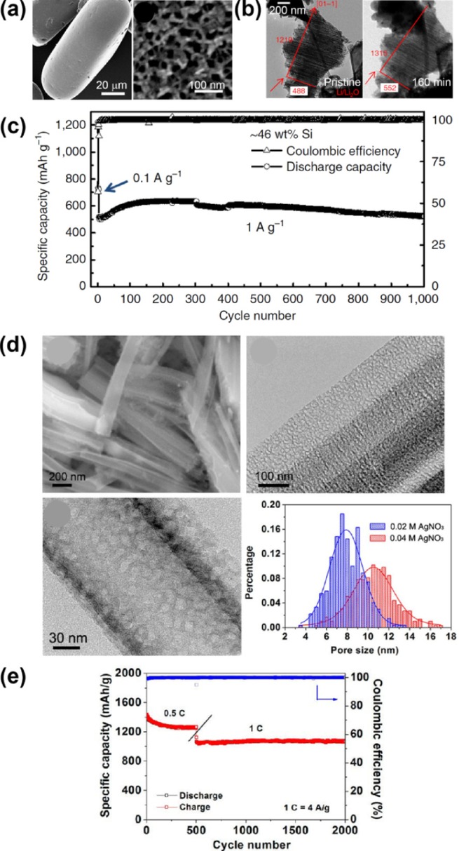
Mesoporous silicon sponge (MSS) (a–c)[26] and porous boron-doped silicon nanowires (d,e).[27] a) SEM images of MSS in low magnification and high magnification. b) In situ TEM images of MSS before lithiation (left) and after 160 min of lithiation (right). c) Cycle performance of MSS for 1000 cycles. d) Morphological investigation of porous boron-doped silicon nanowires with SEM (upper left), TEM analysis and pore-size distribution. e) Cycle performance of the porous boron-doped silicon nanowire. Reprinted with permission from Refs. [26,27]]. Copyright 2014, Macmillan Publishers Ltd; Copyright 2012, American Chemical Society.
Porous Si has also attracted considerable attention for industrial applications owing to the demonstration of scalable top-down processes such as wet etching in almost all studies covering porous Si.25b,[28] Recently, Ge et al. reported the large-scale fabrication of porous Si from cheap metallurgical Si through simple stain etching with HF and Fe(NO3)3 (Figure 3 a).[29] The resulting porous Si had an exposed surface area of 70 m2 g−1; a pore volume of 0.133 cm3 g−1 with nanopores; and a porosity of 22±3 %, which was estimated by 3D tomography. This porous Si exhibited an enhanced cycling performance for 160 cycles compared with non-etched metallurgical Si, retaining a capacity of >1,400 mAh g−1 at 0.2 C. Zhang et al. suggested another scalable synthesis method for porous Si/C composites that employs the Rochow reaction, which is the most economical way to produce organosilane monomers (Figures 3 b,c).[30] They utilized unreacted waste comprising Si, metal compounds, and deposited C and synthesized porous Si/C composites by acid washing, carbonization at 900 °C, and wet etching. The resulting porous Si/C composite was 2–60 μm in size and contained micropores of 2–5 μm in size with a coated C layer and an interfacial space between the Si and C layer, which enables the average capacity-fading rate to be as low as 0.15 % per cycle for 100 cycles. Although top-down method can be considered wasteful, the economic production of porous Si is possible when cheap reactants are utilized, as in the aforementioned examples.
Figure 3.
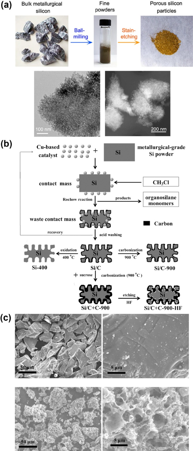
Scalable porous silicon (a)[29] and porous silicon/carbon composite (b,c).[30] a) Synthesis of porous silicon particles and morphological characterization with TEM analysis. b) Synthesis of porous silicon/carbon composites through the Rochow reaction. c) SEM images of bulk Si powder (top) and the porous silicon/carbon composite (bottom). Reprinted with permission from Refs. [29,30]]. Copyright 2014, American Chemical Society; Copyright 2014, John Wiley & Sons, Inc.
2.4. Shape-Preserving Shell
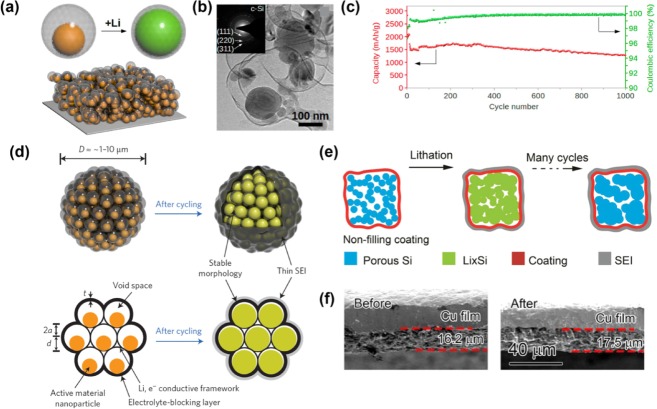
Since the first report of the design of Si with a shape-preserving C shell in 2010,[31] this architecture has attracted attention as an effective model for volume-change-accommodating electrodes. Hertzberg et al. developed an ingenious Si deformation model with a suitable nanospace (Figure 4 a) and then fabricated a thin Si tube confined by a Li-ion permeable C-shell layer (Figure 4 b). In this design, the rigid C shell allows the Si–Li alloy to expand inward rather than outward, preventing the entire electrode from undergoing Si volume expansion. This distinctive behavior yields stable SEI formation upon cycling because the continued growth of the SEI layer is restricted owing to the prevention of the morphologic changes in the external surface area. Thus, stable cycling performances for over 250 cycles demonstrated that this design effectively improved the electrode stability, exhibiting an average CE greater than 99.6 % after the first cycle (Figure 4 c). Similarly, Cui's group designed a series of analogous concepts: a double-walled Si nanotube[32] (Figure 4 d); a yolk–shell design[33] (Figure 5 a); a pomegranate-inspired design[34] (Figure 5 d); and, most recently, a micrometer-sized porous Si particle with a nonfilling C coating[35] (Figure 5 e). Wu et al. suggested a double-walled Si nanotube comprising inner Si and outer Si oxide as a mechanical clamping layer. Although the electrochemical test was performed with a small mass loading (0.02–0.1 mg cm−2), this architecture set the world record for the stable cycling of a Si anode with 6000 cycles at 12 C (Figure 4 e). To develop the industrially scalable fabrication of Si anodes, a yolk–shell design comprising a commercial Si nanoparticle yolk and a 5–10 nm-thick C shell was developed by Liu et al. (Figure 5 b).[33] The electric and ionic conducting C shell and empty space between the yolk and shell allowed the Si to be lithiated and delithiated steadily for 1000 cycles (Figure 5 c). Recently, inspired by the yolk–shell structure, a pomegranate-inspired structure wherein the primary particles (yolk–shell) formed the secondary particles (pomegranate) through bottom-up micro emulsion was developed, exhibiting an increase in the tap density and a high mass loading with a stable, long cycle life.[34] On the other hand, a micrometer-sized porous Si particle with a nonfilling C coating was designed for practical applications by reducing the cost and improving volumetric capacity with a high mass loading.[35] The cross-sectional scanning-electron-microscopy (SEM) analysis supported the effectiveness of the volume-change accommodation for the structure (Figure 5 f).[35] In conclusion, taking a panoramic view of the research on the shape-preserving shell design, these strategies clearly prevent side reactions due to electrolyte decomposition and mechanical fractures, thereby realizing the stable cycling of the Si anode.
Figure 4.
Silicon tubes with shape-preserving shell of carbon (a–c)[31] and SiOx (d,e).[32] a) Schematic of silicon tube with a carbon shell. b) SEM (left) and TEM (right) images of the silicon tube with carbon shell. c) Cycle stability of the silicon tube with carbon shell. d) Schematic of double-walled silicon nanotube showing stable SEI layer during cycling. e) Long-term cycle performance of double-walled silicon nanotube. Reprinted with permission from Refs. [31,32]. Copyright 2010, American Chemical Society; Copyright 2012, Macmillan Publishers Ltd.
Figure 5.
Yolk–shell structures (a–c)[33] and recent studies with shape-preserving carbon shells (d–f).[34,35] a) Schematic of yolk–shell-type design. b) TEM images of yolk–shell-type Si. c) Cycle stability of yolk-shell type Si. d) Schematic of pomegranate-structured silicon describing snug void spaces for volume expansion and stable SEI layer after cycling. e) Schematic of nonfilling carbon coating of porous micrometer-sized silicon particles. f) Investigation of thickness change of the electrode after 100th cycle with SEM images. Reprinted with permission from Refs. [33–35]. Copyright 2012, American Chemical Society; Copyright 2014, Macmillan publishers Ltd.; Copyright 2015, American Chemical Society.
2.5. Graphene Composites
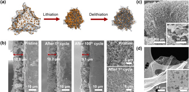
Graphene has received great attention for many years as an ideal matrix of composite materials for high-performance LIB anodes owing to their excellent electronic and mechanical properties.[36] In this regard, the impressive beneficial properties of graphene, such as a great electrical conductivity and high flexibility, can be utilized on Si composites to provide an electrical network throughout the whole electrode and accommodate the volume changes of Si during the electrochemical cycling. Recently, remarkable behavior of a graphene-based Si nanocomposite was reported by Ko et al. (Figures 6 a,b).[37] They succeeded in the facile fabrication of an idealized composite structure by a modified Hummers method and the thermal decomposition of silane gas (SiH4). The composite exhibited island-shaped amorphous Si nanoparticles (a-SiNPs) <10 nm in size that were strongly anchored on the graphene backbone and very well distributed over the entire graphene surface (Figures 6 c,d). The a-Si characteristic and island morphology effectively relieved the induced strain and stress and prevented the interference between adjacent particles during the volume expansion. In addition, the highly flexible graphene yielded a synergetic effect with a critical size of a-SiNPs for elastic behavior, providing an unprecedented decrease in electrode thickness after cycling as a result of self-compacting. This indicates that the fabricated electrode with loosely interconnected composite sheets self-compacted until reaching the rational electrode thickness with the proper agglomeration during cycling without any cracks on its surface. Hence, this sample exhibited outstanding performance in mitigating the detrimental effects of the volume expansion/contraction and improving electronic conductivity, charge transfer, and Li-ion diffusion. As a result, a high specific reversible capacity, excellent power capability, and good cycling stability during 1000 cycles were achieved. Furthermore, a full cell test demonstrated remarkable capacity retention at fast charge/discharge rates. Hence, continuous investment and research for applying graphene to Si anodes are required for the development of next-generation anode materials.
Figure 6.
Amorphous silicon/graphene composite. a) Schematic of Si/Graphene composite exhibiting self-compacting behavior during cycling. b) Electrode thickness decrease of the composite after 100th cycle and top view SEM images of the electrode before and after 1st cycle. c) Low-magnification and high-magnification (inset) SEM images of highly porous graphene sheets. d) High-resolution TEM images of amorphous silicon/graphene composite in low and high magnification (inset). Reprinted with permission from Ref. [37]. Copyright 2014, American Chemical Society.
3. Conclusions and Outlook
Severe volume change during cycling, which has a deleterious effect on battery performance, is the most critical challenge to be resolved in Si anodes. We discussed outstanding strategies for realizing a volume-change-accommodating electrode with a sophisticated architecture of Si anodes. Developing a porous nanosized Si structure is an essential preliminary approach for alleviating the induced stress and stimulating the electrochemical properties. A patterned thin-film structure allows a high rate capability and cycle stability with elastic behavior during the Li insertion/extraction process. Besides, a porous structure can yield a marginal volume when Si becomes lithiated and also provides large active sites, incorporating the increased specific surface area of numerous pores. However, the high specific area generally creates serious side reactions with electrolyte decomposition, yielding a low CE and an increase in the internal resistance due to by-products.[18] To cope with the side reactions and the volume-change problem, a shape-preserving shell design was devised that not only maintains the integrity of the Si via confined voids in its composites but also enables the stable formation of the SEI layer. The graphene composite presents impressive potential for accommodating volume changes, together with excellent electrical and mechanical properties and flexibility, resulting in self-compacting behavior.
These efforts regarding the volume-change problem have certainly yielded progress toward the practical application of Si anodes. However, several challenges remain to be resolved. First, the development of novel surface-coating methods and stable electrolytes to reduce the side reactions is an impressive challenge, especially for nanostructured Si. In addition, reducing the HF derived from fluoroethylene carbonate (FEC), which is widely used in Si anodes to stabilize the SEI layer, is required because substantial capacity fading occurs as the HF attacks both the cathodes[38] and Si.[39] Second, the relatively low density of nano- and porous structures can decrease the volumetric energy density.15b Therefore, the elaborate tailoring of the porosity in the electrode is necessary to prevent an undesirable decrease in the volumetric energy density. Finally, in order to apply the Si anode to commercial LIBs and achieve a high energy density, the change in the electrode thickness after tens of cycles should be examined in calendered Si anodes having an electrode density greater than 1.6 g cc−1, as an industrial standard.
Acknowledgments
This work was supported by the IT R&D program of the Ministry of Trade, Industry & Energy/Korea Evaluation Institute of Industrial Technology (MOTIE/KEIT) (Development of Li-rich Cathode and Carbon-free Anode Materials for High Capacity/High Rate Lithium Secondary Batteries, 10046309).
References
- 1a.Kim TH, Park JS, Chang SK, Choi S, Ryu JH, Song HK. Adv. Energy Mater. 2012;2:860. [Google Scholar]
- 1b.Choi NS, Chen ZH, Freunberger SA, Ji XL, Sun YK, Amine K, Yushin G, Nazar LF, Cho J, Bruce PG. Angew. Chem. Int. Ed. 2012;51:9994. doi: 10.1002/anie.201201429. [DOI] [PubMed] [Google Scholar]
- Angew. Chem. 2012;124:10134. [Google Scholar]
- 1c.Etacheri V, Marom R, Elazari R, Salitra G, Aurbach D. Energy Environ. Sci. 2011;4:3243. [Google Scholar]
- 2. Electrochemical Energy Storage Technical Team Roadmap, U. S. Drive 2013.
- 3. Secondary Battery Technology Development Roadmap, NEDO, 2013.
- 4.Obrovac MN, Chevrier VL. Chem. Rev. 2014;114:11444–11502. doi: 10.1021/cr500207g. [DOI] [PubMed] [Google Scholar]
- 5.Nitta N, Yushin G. Part. Part. Syst. Charact. 2014;31:317. [Google Scholar]
- 6a.Obrovac MN, Christensen L. Electrochem. Solid-State Lett. 2004;7:A93. [Google Scholar]
- 6b.Obrovac MN, Krause LJ. J. Electrochem. Soc. 2007;154:A103. [Google Scholar]
- 7.Jung HJ, Park M, Yoon YG, Kim GB, Joo SK. J. Power Sources. 2003;115:346. [Google Scholar]
- 8.Reece SY, Hamel JA, Sung K, Jarvi TD, Esswein AJ, Pijpers JJH, Nocera DG. Science. 2011;334:645. doi: 10.1126/science.1209816. [DOI] [PubMed] [Google Scholar]
- 9.Ghadbeigi L, Harada JK, Lettiere BR, Sparks TD. Energy Environ. Sci. 2015;8:1640. [Google Scholar]
- 10.Pollak E, Salitra G, Baranchugov V, Aurbach D. J. Phys. Chem. C. 2007;111:11437. [Google Scholar]
- 11a.Pharr M, Zhao K, Wang X, Suo Z, Vlassak JJ. Nano Lett. 2012;12:5039. doi: 10.1021/nl302841y. [DOI] [PubMed] [Google Scholar]
- 11b.Cui Z, Gao F, Qu J. J. Mech. Phys. Solids. 2012;60:1280. [Google Scholar]
- 11c.Gao YF, Zhou M. J. Appl. Phys. 2011;109:014310. [Google Scholar]
- 12a.McDowell MT, Lee SW, Nix WD, Cui Y. Adv. Mater. 2013;25:4966. doi: 10.1002/adma.201301795. [DOI] [PubMed] [Google Scholar]
- 12b.McDowell MT, Lee SW, Harris JT, Korgel BA, Wang CM, Nix WD, Cui Y. Nano Lett. 2013;13:758. doi: 10.1021/nl3044508. [DOI] [PubMed] [Google Scholar]
- 13.Zhao H, Yuan W, Liu G. Nano Today. 2015;10:193–212. [Google Scholar]
- 14a.Kasavajjula U, Wang CS, Appleby AJ. J. Power Sources. 2007;163:1003. [Google Scholar]
- 14b.Teki R, Datta MK, Krishnan R, Parker TC, Lu TM, Kumta PN, Koratkar N. Small. 2009;5:2236. doi: 10.1002/smll.200900382. [DOI] [PubMed] [Google Scholar]
- 14c.Szczech JR, Jin S. Energy Environ. Sci. 2011;4:56. [Google Scholar]
- 14d.Wu H, Cui Y. Nano Today. 2012;7:414. [Google Scholar]
- 14e.Su X, Wu QL, Li JC, Xiao XC, Lott A, Lu WQ, Sheldon BW, Wu J. Adv. Energy Mater. 2014;4:1300882. [Google Scholar]
- 15a.Lee KT, Cho J. Nano Today. 2011;6:28. [Google Scholar]
- 15b.Bruce PG, Scrosati B, Tarascon JM. Angew. Chem. Int. Ed. 2008;47:2930. doi: 10.1002/anie.200702505. [DOI] [PubMed] [Google Scholar]
- Angew. Chem. 2008;120:2972. [Google Scholar]
- 15c.Mahmood N, Hou Y. Adv. Sci. 2014;1:140012. doi: 10.1002/advs.201400012. [DOI] [PMC free article] [PubMed] [Google Scholar]
- 16.Liu XH, Zhong L, Huang S, Mao SX, Zhu T, Huang JY. ACS Nano. 2012;6:1522. doi: 10.1021/nn204476h. [DOI] [PubMed] [Google Scholar]
- 17.Kim H, Seo M, Park MH, Cho J. Angew. Chem. Int. Ed. 2010;49:2146. doi: 10.1002/anie.200906287. [DOI] [PubMed] [Google Scholar]
- Angew. Chem. 2010;122:2192. [Google Scholar]
- 18.Aricò AS, Bruce P, Scrosati B, Tarascon J-M, van Schalkwijk W. Nat. Mater. 2005;4:366. doi: 10.1038/nmat1368. [DOI] [PubMed] [Google Scholar]
- 19a.Hatchard TD, Dahn JR. J. Electrochem. Soc. 2004;151:A838. [Google Scholar]
- 19b.Kulova TL, Skundin AM, Pleskov YV, Kon′Kov OI, Terukov EI, Trapeznikova IN. Chem. Biochem. Eng. Q. 2007;21:83–92. [Google Scholar]
- 19c.Kulova TL, Skundin AM, Pleskov YV, Terukov EI, Kon′kov OI. J. Electroanal. Chem. 2007;600:217. [Google Scholar]
- 19d.Peng B, Cheng FY, Tao ZL, Chen J. J. Chem. Phys. 2010;133:034701. doi: 10.1063/1.3462998. [DOI] [PubMed] [Google Scholar]
- 19e.Sethuraman VA, Chon MJ, Shimshak M, Srinivasan V, Guduru PR. J. Power Sources. 2010;195:5062. [Google Scholar]
- 19f.Soni SK, Sheldon BW, Xiao X, Verbrugge MW, Ahn D, Haftbaradaran H, Gao H. J. Electrochem. Soc. 2012;159:A38. [Google Scholar]
- 20.Xiao X, Liu P, Verbrugge MW, Haftbaradaran H, Gao H. J. Power Sources. 2011;196:1409. [Google Scholar]
- 21.Baggetto L, Danilov D, Notten PH. Adv. Mater. 2011;23:1563. doi: 10.1002/adma.201003665. [DOI] [PubMed] [Google Scholar]
- 22.He Y, Yu X, Wang Y, Li H, Huang X. Adv. Mater. 2011;23:4938. doi: 10.1002/adma.201102568. [DOI] [PubMed] [Google Scholar]
- 23.Park MS, Wang GX, Liu HK, Dou SX. Electrochim. Acta. 2006;51:5246. [Google Scholar]
- 24.Kim SW, Yun JH, Son B, Lee YG, Kim KM, Lee YM, Cho KY. Adv. Mater. 2014;26:2977. doi: 10.1002/adma.201305600. [DOI] [PubMed] [Google Scholar]
- 25a.Cho J. J. Mater. Chem. 2010;20:4009. [Google Scholar]
- 25b.Ge M, Fang X, Rong J, Zhou C. Nanotechnology. 2013;24:422001. doi: 10.1088/0957-4484/24/42/422001. [DOI] [PubMed] [Google Scholar]
- 25c.Vu A, Qian YQ, Stein A. Adv. Energy Mater. 2012;2:1056. [Google Scholar]
- 26.Li XL, Gu M, Hu SY, Kennard R, Yan PF, Chen XL, Wang CM, Sailor MJ, Zhang JG, Liu J. Nat. Commun. 2014;5:4105. doi: 10.1038/ncomms5105. [DOI] [PubMed] [Google Scholar]
- 27.Ge MY, Rong JP, Fang X, Zhou CW. Nano Lett. 2012;12:2318. doi: 10.1021/nl300206e. [DOI] [PubMed] [Google Scholar]
- 28a.Bang BM, Kim H, Song HK, Cho J, Park S. Energy Environ. Sci. 2011;4:5013. [Google Scholar]
- 28b.Bang BM, Lee JI, Kim H, Cho J, Park S. Adv. Energy Mater. 2012;2:878. [Google Scholar]
- 29.Ge MY, Lu YH, Ercius P, Rong JP, Fang X, Mecklenburg M, Zhou CW. Nano Lett. 2014;14:261. doi: 10.1021/nl403923s. [DOI] [PubMed] [Google Scholar]
- 30.Zhang ZL, Wang YH, Ren WF, Tan QQ, Chen YF, Li H, Zhong ZY, Su FB. Angew. Chem. Int. Ed. 2014;53:5165–5169. doi: 10.1002/anie.201310412. [DOI] [PubMed] [Google Scholar]
- Angew. Chem. 2014;126:5265–5269. [Google Scholar]
- 31.Hertzberg B, Alexeev A, Yushin G. J. Am. Chem. Soc. 2010;132:8548. doi: 10.1021/ja1031997. [DOI] [PubMed] [Google Scholar]
- 32.Wu H, Chan G, Choi JW, Ryu I, Yao Y, McDowell MT, Lee SW, Jackson A, Yang Y, Hu LB, Cui Y. Nat. Nanotechnol. 2012;7:309–314. doi: 10.1038/nnano.2012.35. [DOI] [PubMed] [Google Scholar]
- 33.Liu N, Wu H, McDowell MT, Yao Y, Wang CM, Cui Y. Nano Lett. 2012;12:3315. doi: 10.1021/nl3014814. [DOI] [PubMed] [Google Scholar]
- 34.Liu N, Lu ZD, Zhao J, McDowell MT, Lee HW, Zhao WT, Cui Y. Nat. Nanotechnol. 2014;9:187. doi: 10.1038/nnano.2014.6. [DOI] [PubMed] [Google Scholar]
- 35.Lu Z, Liu N, Lee H-W, Zhao J, Li W, Li Y, Cui Y. ACS Nano. 2015;9:2540. doi: 10.1021/nn505410q. [DOI] [PubMed] [Google Scholar]
- 36a.Bonaccorso F, Colombo L, Yu G, Stoller M, Tozzini V, Ferrari AC, Ruoff RS, Pellegrini V. Science. 2015;347:1246501. doi: 10.1126/science.1246501. [DOI] [PubMed] [Google Scholar]
- 36b.Raccichini R, Varzi A, Passerini S, Scrosati B. Nat. Mater. 2015;14:271. doi: 10.1038/nmat4170. [DOI] [PubMed] [Google Scholar]
- 37.Ko M, Chae S, Jeong S, Oh P, Cho J. ACS Nano. 2014;8:8591. doi: 10.1021/nn503294z. [DOI] [PubMed] [Google Scholar]
- 38.Aurbach D, Markovsky B, Rodkin A, Levi E, Cohen YS, Kim HJ, Schmidt M. Electrochim. Acta. 2002;47:4291. [Google Scholar]
- 39.Blumberg AA, Stavrinou SC. The Journal of Physical Chemistry. 1960;64:1438. [Google Scholar]


