

Abstract
This paper presents a new method, called multi-cycle Q-modulation, which can be used in wireless power transmission (WPT) to modulate the quality factor (Q) of the receiver (Rx) coil and dynamically optimize the load impedance to maximize the power transfer efficiency (PTE) in two-coil links. A key advantage of the proposed method is that it can be easily implemented using off-the-shelf components without requiring fast switching at or above the carrier frequency, which is more suitable for integrated circuit design. Moreover, the proposed technique does not need any sophisticated synchronization between the power carrier and Q-modulation switching pulses. The multi-cycle Q-modulation is analyzed theoretically by a lumped circuit model, and verified in simulation and measurement using an off-the-shelf prototype. Automatic resonance tuning (ART) in the Rx, combined with multi-cycle Q-modulation helped maximizing PTE of the inductive link dynamically in the presence of environmental and loading variations, which can otherwise significantly degrade the PTE in multi-coil settings. In the prototype conventional 2-coil link, the proposed method increased the power amplifier (PA) plus inductive link efficiency from 4.8% to 16.5% at (RL = 1 kΩ, d23 = 3 cm), and from 23% to 28.2% at (RL = 100 Ω, d23 = 3 cm) after 11% change in the resonance capacitance, while delivering 168.1 mW to the load (PDL).
Index Terms: Inductive link, impedance matching, power management, load modulation, Q-modulation, wireless power transmission
I. Introduction
Near-field wireless power transmission (WPT) has been utilized for contactless powering in a wide variety of applications. Charging mobile devices and electric vehicles are the leading applications for WPT by significantly improving the user experience, ease of use, and convenience [1]–[9]. Implantable microelectronic devices (IMDs) form another key category of devices that is significantly benefiting from advancements in WPT. Because eliminating the transcutaneous interconnects and large batteries that would otherwise be needed to operate IMDs over extended periods is necessary to reduce their invasiveness and improve patient safety [10]–[16].
Most IMDs have strict power restrictions to limit heat dissipation in the coils/tissue, exposure to electromagnetic field, and interference with other devices [17]–[21]. Such WPT systems need to have sufficient power delivered to the load (PDL), while maintaining high power transfer efficiency (PTE) [18]. Considerable attention has been paid to maximizing PTE in 2-, 3-, and 4-coil inductive links by optimizing the geometry of the coils [18], [22]–[27]. The PTE between the conventional 2-coil links degrades with load variation because the PTE is affected by the loaded quality factor (Q) of the receiver (Rx) LC-tank [28]. On the other hand, the 3- and 4-coil inductive links offer additional degrees of freedom to transform any given load to the optimal loading condition that maximizes the PTE, at the cost of increased size and complexity of the Rx. Furthermore, dynamic optimization during system operation is difficult, if not impossible, because the load matching in the 3-and 4-coil links require adjusting the geometry and mutual coupling of the coils. Other methods for the load transformation using L, π, and T-match networks have been presented also [29], [30]. While any load can be transformed to the optimal value, the limitations of size, complexity, additional power loss, and inability to react dynamically still remain.
More recently, there have been efforts to modulate the load using DC-DC converters in order to increase the Q-factor of the Rx coil in the 2-coil links [31], [32]. However, these systems cannot automatically find the optimal matching conditions to maximize the PTE and only compensate load variations in a limited range due to inherent limitations of the DC-DC converters. The Q-modulation technique, which was first introduced in [33], adaptively transforms the Rx loading to dynamically maximize the PTE in 2-coil inductive links during operation. While the fully-integrated Q-modulation power management application-specific integrated circuit (ASIC) in [33] successfully improved the PTE for a wide range of load variations, implementation of that method using commercial off-the-shelf (COTS) components would be difficult. Because in the Q-modulation technique in [33], the Rx LC-tank is chopped very rapidly, twice for every power carrier period, requiring sophisticated synchronization between the current in the Rx LC-tank and the timing of chopping switch.
Digital control of the duty cycle in [33] needs a clock rate much faster than the power carrier frequency, e.g. 100 times faster for 2% resolution in duty cycle control. Alternatively, analog control of the duty cycle would require accurate charge pump with adjustable output to set the duty cycle of the switching pulses, which adds to the complexity of the circuit needed to generate the switching pulses. This would limit the use of higher power carrier frequencies in the inductive links that utilize Q-modulation technique. If the timing of chopping switch is not properly synchronized with the carrier, the Q-modulation in [33] could degrade the PTE, while the method presented in this paper is considerably more robust.
In addition to the load variation in the Rx LC-tank, the PTE is also highly dependent on how well the transmitter (Tx) and Rx tank circuits are tuned at the operating frequency, fp, because the inductive link is often adversely affected by the parasitic capacitance of the surrounding tissue environment or the process variations, which can significantly degrade the PTE, particularly when the Q-factor is high [28], [34]. Several adaptive tuning methods for the Rx LC-tank have been proposed by employing a variable LC-tank to compensate for variations in the Rx resonance capacitance [35]–[39]. Such adaptive Rx LC-tank tuning techniques would be important in Q-modulation because chopping the Rx LC-tank can affect its resonance frequency, and it needs to be continuously compensated along with matching the load impedance with that of the inductive link to maximize the PTE.
In this paper, we demonstrate a new Q-modulation method that can span across multiple carrier cycles without requiring complex circuits and sophisticated synchronization between the current in the receiver LC-tank and the timing of coil switching. As such, the new multi-cycle Q-modulation technique is easy to implement in either COTS or ASIC platforms, regardless of the power carrier frequency. We have combined the proposed multi-cycle Q-modulation with automatic resonance tuning (ART), for the first time, in a prototype utilizing COTS components, such as a rectifier, regulator, analog switch, capacitor bank, and microcontroller (MCU), as shown in Fig. 1. The series Rx LC-tank is composed of L3 and C3+ΔCART with its parasitic resistance, R3, and it is assumed that the Rx LC-tank is always resonant at fp because ΔCART is adaptively adjusted to maintain the resonant condition via ART operation. The power amplifier (PA) can be modeled with a sinusoidal voltage source, VS, plus its output impedance, RS. The Tx LC-tank is composed of L2, C2, and the series resistance, R2. The mutual inductance, M23, is decided by the coupling coefficient, k23, and the Tx and Rx coil inductances, L2 and L3. We have also derived the governing equations over the new multi-cycle Q-modulation technique using a lumped circuit model, and verified them via simulation and measurements. The ART combined with multi-cycle Q-modulation keeps the PTE of the inductive link at its peak dynamically by simultaneously matching the load and tuning the Rx LC-tank at the carrier frequency, fp. In section II, the lumped model and analysis of the proposed multi-cycle Q-modulation method are introduced in a 2-coil inductive link. The theoretical calculation, simulation, and measurement results of the multi-cycle Q-modulation inductive link are depicted in section III. The control algorithm for the multi-cycle Q-modulation and ART combination are presented in section IV. Implementation and experimental results are described in section V, followed by concluding remarks.
Fig. 1.
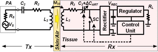
Block diagram of a multi-cycle Q-modulation with automatic resonance tuning (ART), which adaptively transforms any arbitrary load to the optimal loading and tunes the Rx LC-tank at the carrier frequency for continuous operation at the highest PTE.
II. Modeling and Analysis of Multi-Cycle Q-Modulation
Fig. 2a shows a lumped model of the proposed multi-cycle Q-modulation inductive link along with its switching waveforms in Fig. 2b. The parasitic components are not considered in the lumped model of the proposed Q-modulation inductive link in Fig.2 to avoid the complex analysis. In the conventional 2-coil inductive link, the PTE can be derived as [25],
| (1) |
where k23 = M23/(L2L3)0.5, Q2 = ωL2/R2, and Q3L = Q3QL/(Q3+QL), in which ω=2πfp, Q3 = ωL3/R3 and QL = RL / ωL3. The high quality factors of Q2, Q3, and Q3L are desirable to achieve high PTE in a 2-coil inductive link. During coil optimization, Q2 and Q3 are decided by their geometrical limitation and carrier frequency, and Q3L is limited by the load resistance. The Q-modulation technique proposed in this paper modulates the loaded Q-factor, Q3L, in the Rx coil by the switched L3C3-tank to transform RL into optimal equivalent load, Ropt, for optimization of the 2-coil inductive link. Two control parameters are employed to achieve the highest PTE in the multi-cycle Q-modulation technique: 1) the switching time, Ton, and 2) the switching period, Tnp, both of which are multiple times longer than the carrier period, Tp = 1/fp. The SC signal closes or opens a switch with its ON resistance of RSW to modulate the load, RL, and maximize the voltage across the load, VL, and consequently the received power.
Fig. 2.
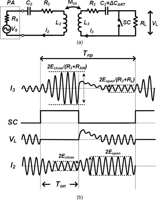
(a) The circuit model of the proposed multi-cycle Q-modulation with ART inductive link. (b) Voltage and current waveforms, controlled by Ton and Tnp.
The equivalent circuit of Fig. 2a is shown in Fig. 3a, in which ω = 2πfp, R22 = RS + R2, VS(t)=E0cos(ωt), and C3′ = C3 + ΔCART. The equivalent resistance, R33, is R3 + RSW for 0 ≤ t < Ton, and R3+RL for Ton ≤ t < Tnp where RSW is the ON resistance of the SC switch (RSW ≪ RL). V23 and V32 in the equivalent circuit can be found from,
| (2) |
| (3) |
The reflected impedance onto the primary side, Zref, can be derived from,
| (4) |
Fig. 3.
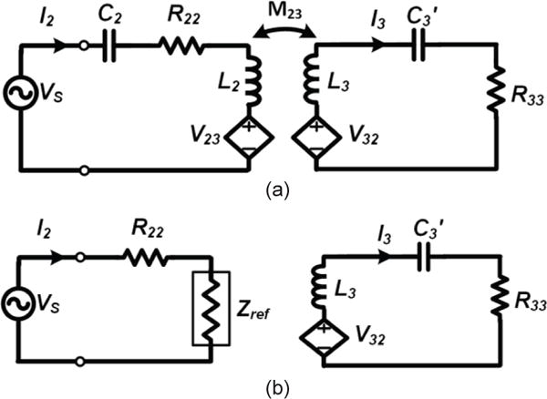
(a) Equivalent circuit of lumped model in Fig. 2a. (b) Simplified equivalent circuit seen from the primary (Tx) side at resonance. The secondary (Rx) side is maintained because of its effect on the transient mode calculations.
Assuming that L2 and C2 on the primary (Tx) side are tuned at fp, the equivalent circuit seen from the primary and secondary sides can be simplified to what is shown in Fig. 3b. When L3C3-tank is also tuned at fp, the primary current, I2, and the secondary reflected voltage, V32, in the steady-state condition can be calculated as,
| (5) |
| (6) |
Therefore, the steady-state current in the Rx, I3(t), can be derived by Kirchhoff’s voltage law (KVL),
| (7) |
| (8) |
Since R33 is either R3+RSW or R3+RL during Q-modulation we substitute E1 with Eclose and Eopen, which imply the steady-state amplitudes of I2(t) for 0 ≤ t < Ton and Ton ≤ t< Tnp, respectively. When SC is closed, the Rx circuit would be underdamped due to its small parasitic resistance and (7) can be solved by summing the particular integral (9) and the complementary function (10),
| (9) |
| (10) |
| (11) |
where α = (R3+RSW)/2L3. Considering the initial condition from t = 0−, where SC is opened, the secondary steady-state current during 0 ≤ t < Ton can be found from,
| (12) |
When SC is open at t = Ton+, the energy stored in the L3C3-tank is transferred to RL. Since the load has a relatively large resistance compared to RSW, the circuit condition is normally over-damped and the solution for (7) takes the form of,
| (13) |
where,
| (14) |
| (15) |
| (16) |
The two initial conditions, I3,close(Ton−) = 0 and VC(Ton−), which is the voltage across C3′ at t = Ton−, that are needed to solve (13) can be iteratively calculated from (12) by utilizing the new initial condition from (13) in the transient state.
Although the transient waveforms of I3,close(t) and I3,open(t) can be derived from (11) and (13), the transient voltages reflected onto the secondary side, Eclose(t) and Eopen(t), are also affected by the LCR components on both primary and secondary sides while both L2C2- and L3C3-tanks are tuned at fP. It is necessary to solve the overall transient equation derived from Fig. 3a to extract the exact waveforms for Eclose(t) and Eopen(t),
| (17) |
| (18) |
Since (17) and (18) create a 4th order differential equation, we estimate the transient voltage for Eclose(t) and Eopen(t) in this paper, when the overall system is in the over-damped condition,
| (19) |
| (20) |
where α = (RS+R2)/2L2.
Assuming that the Tx and Rx LC-tanks are fully resonated, VS and I2 are in-phase because the reflected load in (4) has only the real part. The estimated transient voltage for Eclose(t) and Eopen(t) are used to calculate VS output power in the transient state. Since power is only delivered to the load when SC is open Ton ≤ t < Tnp, the PDL and VS (source) output power for the multi-cycle Q-modulation can be derived from,
| (21) |
| (22) |
| (23) |
| (24) |
where PL,Qmod,average is the PDL, PVs,close,rms is the power drained from VS for 0 ≤ t < Ton, PVs,open,rms is the power drained from VS for Ton ≤ t< Tnp, and PVs,Qmod,average is the average power drained from VS. Moreover, the PA + link efficiency can be calculated as,
| (25) |
The proposed Q-modulation boosted Q3L equal to Q3 during t < Ton, and the boosted energy is stored in the Rx LC-tank although the power is not transferred to the load compared to the conventional 2-coil inductive link without the Q-modulation, which transfer the continuous inductive power to the load with relatively low Q3L due to low QL. The stored energy in the Rx LC-tank is transferred to the load during Tnp−Ton, to achieve the modulated loaded quality factor, Q3L,eq, which can be found from Q3L,eq = Q3QL,eq/(Q3+QL,eq), where QL,eq = ωL3/Ropt, and Ropt = (1−Ton/Tnp)RL.
III. Verification of Theoretical Model of Multi-Cycle Q-Modulation
The key parameters used in calculation, simulation, and proof-of-concept prototype measurement setup of the multi-cycle Q-modulation method are summarized in the Table I. The carrier frequency was chosen at 13.56 MHz in the industrial-scientific and medical (ISM) band. The Tx planar spiral coil (PSC) and Rx wire-wound coil are designed for a nominal distance of 3 cm and have a measured k23 = 0.044. The class-E PA used in the measurement setup had an output impedance of 3.1 Ω, and the switching resistance of the MOSFET pair (DMN5L06K) used for Q-modulation in the prototype Rx was 2 × 2 Ω.
TABLE I.
Prototype Multi-Cycle Q-Modulation Inductive Link Specifications
| Parameters | Value |
|---|---|
| PSC primary coil (L2) | Inductance = 5.8 μH Outer diameter = 4 cm Line width = 0.4 mm Line spacing = 0.2 mm Number of turns = 9 Quality factor = 187 |
| Wire-wound secondary coil (L3) | Inductance = 3.85 μH Outer diameter = 2.2 cm Wire diameter = 0.2 mm Number of turns = 10 Quality factor = 93.7 |
| Resonance Capacitance | C2 = 23.8 pF, C3 = 36.0 pF |
| L2-L3 nominal distance (d23) | 3 cm |
| Coupling coefficient (k23) | 0.044 |
| Switch Resistance (RSW) | 4 Ω |
| PA output resistance (RS) | 3.1 Ω |
| Carrier frequency (fp) | 13.56 MHz |
| Loading (RL) | 500 Ω |
Using Table I parameters in (21)–(25), and sweeping Ton and Tnp from 1 to 10 power carrier cycles, result in Fig. 4a, which shows how the inductive link PTE changes with multi-cycle Q-modulation. Fig. 4a also shows the optimal values for Ton and Tnp that would maximize the PA + link efficiency, ηQmod.
Fig. 4.
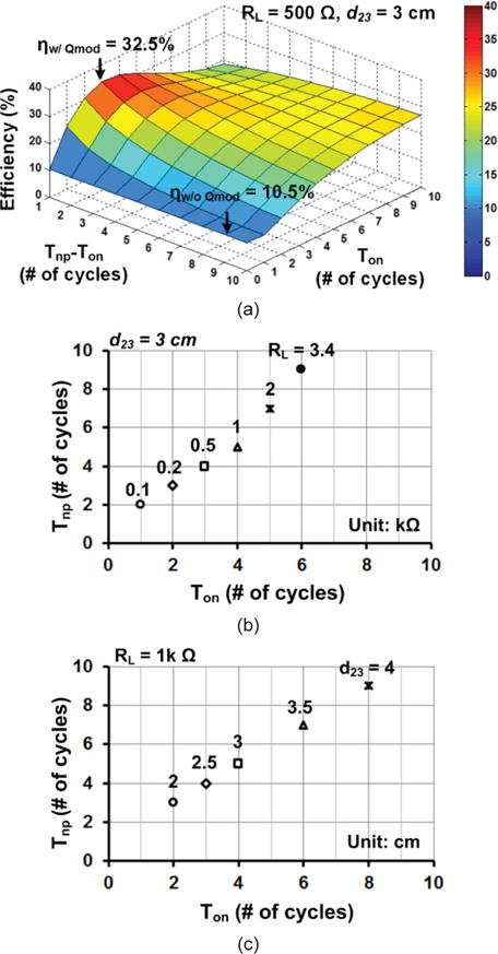
Calculated optimal Ton and Tnp to maximize the PA + link efficiency in 2-coil inductive link using parameters in Table I. (a) Ton = 3TP, Tnp = 4TP at RL = 500 Ω and d23 = 3 cm. (b) Optimal Ton and Tnp vs. load variations at d23 = 3cm. (c) Optimal Ton and Tnp vs. coil distance variations at RL = 1 kΩ.
According to Fig. 4a, with RL = 500 Ω and d23 = 3 cm, the 2-coil inductive link in Table I provides ηw/o Qmod = 10.5% at d23 = 3 cm. Using multi-cycle Q-modulation with Ton = 3Tp, Tnp = 4Tp, the peak efficiency increases to 32.5%, which represents 182% improvement. Moreover, using the same theoretical analysis in section II, we can find how Ton and Tnp should be changed in response to changes in RL and d23, which are the two parameters that often change during operation of the system. These results, which are shown in Figs. 4b and 4c, respectively, indicate that more load modulation is necessary to achieve the maximum ηQmod when RL increases or k23 decreases.
To compare the theoretical model in section II with circuit simulation, we used the Simulink (Mathworks, Natick, MA) environment and parameters in Table I. The calculated and simulated transient waveforms, with Ton = 3Tp, Tnp = 4Tp, RL = 500 Ω, and d23 = 3 cm, using (12) for closed switch, (13) for open switch, and Simulink are presented in Fig. 5a, and show a very good agreement. Fig. 5b shows the calculated, simulated, and measured PA + link efficiency over a wide range of RL, from 100 Ω to 3.4 kΩ. Since the inductive link is designed by the series LC-tank, the measurement result shows higher PA + link efficiency for the smaller RL without the Q-modulation while the efficiency dramatically decreases as RL increases. The external SC pulse (external Q-modulation) generated by the signal generator opens or closes the MOSFET pair in order to verify the effect of the proposed multi-cycle Q-modulation. Because of the approximations in calculating the transient voltage between Eclose(t) and Eopen(t) in (19) and (20) followed by (22) and (23), the calculated and simulated PA + link efficiencies are not perfectly matched in a wide range of RL. Parasitic components in the actual circuit further affect the PA + link efficiency by degrading it in the measurement results with externally applied Q-modulation switching pulse. Nonetheless, the calculated, simulated, and measured efficiencies show similar trends, and the multi-cycle Q-modulation in each case significantly increases ηQmod over a wide range of RL and k23 variations thanks to the dynamic impedance matching capability of the Rx.
Fig. 5.
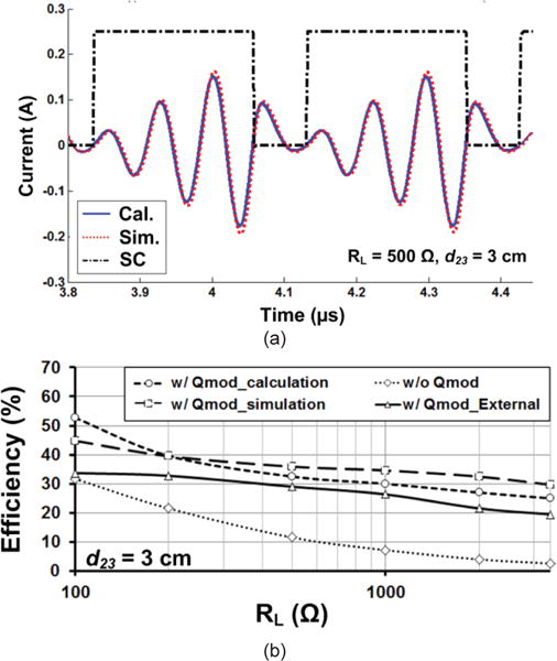
(a) Calculated vs. Simulated transient waveform for l3(t) at RL = 500 Ω and d23 = 3 cm, and other parameters in Table I. (b) PA + link efficiency vs. loading variations from 100 Ω to 3.4 kΩ with and without multi-cycle Q-modulation.
A key advantage of the multi-cycle Q-modulation is that it does not need delicate synchronization between the current in the Rx L3C3-tank and the SC pulse, which might be difficult to achieve when the carrier frequency is high. Although we constructed the lumped circuit model and its waveforms in section II based on the synchronized condition between the switching pulse and the power carrier, adding delay to the SC signal does not affect the circuit performance because in the steady state the energy stored in the L3C3-tank is independent of the delay of the SC signal, but dependent on Ton that spans over multiple periods of TP. Fig. 6 shows the measured ηQmod with fixed Ton and variable delays between the power carrier and SC pulse. The optimal SC pulse periods for several RL and d34 combinations are found from Fig. 4 and the SC signal was generated externally with 0 to 80 ns delay with respect to the power carrier (TP = 73.74 ns). It can be seen that ηQmod is almost independent of the delay of the SC pulse.
Fig. 6.
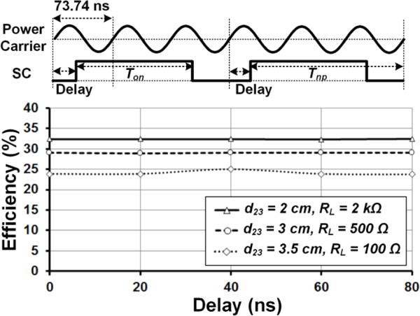
Measured ηQmod for variable delay between the power carrier at 13.56 MHz and the optimal SC pulses for three cases of (d23 = 2 cm, RL = 2 kΩ), (d23 = 3 cm and RL = 500 Ω), and (d23 = 3.5 cm, RL = 100 Ω).
IV. Automatic Resonance Tuning in Multi-Cycle Q-Modulation
It is important to ensure that the Tx and Rx LC-tanks are tuned at the carrier frequency, fp, to achieve the best PTE against changes in the parasitic capacitance of the surrounding environment or various objects around the inductive link. The inductive link in the IMD is often adversely affected by the parasitic capacitance of the surrounding tissue environment, which can significantly degrade the PTE, particularly when the Q-factor is high [34]. Proper tuning of the Rx LC-tank becomes even more important when Q-modulation is employed because of the impact of this technique on boosting the Q of Rx to improve the overall PTE. Moreover, small deviation in C3 due to Q-modulation results in reduction of the stored energy in L3C3-tank, leading to degradation in the PTE more severely than a conventional 2-coil inductive link. Fig. 7 shows the simulated ηQmod vs. variations in C3′ for conventional and Q-modulated 2-coil inductive links at RL = 200 Ω and d23 = 3 cm. A 11.4% variation in C3′ results in 7.5% degradation in the ηQmod of the Q-modulated inductive link, while the same change results in only 2% degradation in the ηw/o Qmod of the conventional 2-coil.
Fig. 7.
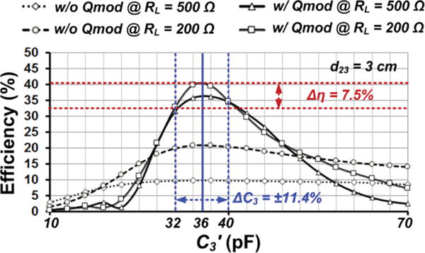
Simulated ηQmod vs. C3′ variations with and without multi-cycle Q-modulation when RL = 200 Ω and d23 = 3 cm. With 11.4% change in C3′, ηQmod decreases by 7.5% in the Q-modulated 2-coil link, while it only decreases by 2% in the conventional 2-coil link.
To resonate the L3C3-tank at fp, a mechanism similar to the ART used in the power management integrated circuit (PMIC) in [37] was adopted, but implemented with COTS components only. Details of the ART design and operation, and its impact on the inductive link are discussed in [37]. The ART constantly tries to find the maximum ηQmod in a closed loop to oppose any capacitance or inductance changes imposed by the surrounding environment, parasitic components, process, or duty-cycle variations. In the current prototype, CART is implemented as a 5-bit binary capacitor bank, swept from 0.15 pF to 11.7 pF by the MCU on the Rx side. Considering the parasitic capacitance of the NMOS switches (~5.9 pF), the implemented ART can compensate the L3C3-tank variations to resonate at fp = 13.56 MHz.
The implemented algorithm in the MCU, shown in Fig. 8, seeks maximum PDL by sweeping Ton and Tnp for the multi-cycle Q-modulation and CART for the ART, while monitoring VREC. Since k12 between the coils in this prototype is small, as shown in Table I, the optimal RL for PTE and PDL is almost the same [25], and the proposed algorithm to monitor VREC in the multi-cycle Q-modulation optimizes the PTE as well. In Fig. 9, the measured PA + link efficiency (PTE) and PDL are shown in the 2-coil inductive link at d23 = 3 cm vs. loading variations from 100 Ω to 3.4 kΩ without multi-cycle Q-modulation. These curves show that the PDL and PTE follow the same trend and their optimization within PTE < 40% lead to the same result. VREC is sampled and digitized before and after stepping Ton to decide the optimal pulse width of the SC signal, during which resonating power builds up in the Rx LC-tank. Then, the optimal Tnp−Ton is decided for transferring the stored energy to RL through the same procedure, while Ton is fixed. In the last step, the optimal CART is decided based on the optimal Ton and Tnp values (see Fig. 8). The optimization order of Ton, Tnp−Ton, and CART is not very important because they are repeatedly optimized during the operation. Since these parameters effects on the PTE independently, they can be optimized individually unless the Rx can’t receive the enough power from the inductive link. This simple iterative process, which has been implemented in an ultra low power MCU (MSP430), can dynamically search for and reach/track the highest available PDL and PTE for any given inductive link combination, unless the PTE distribution in Fig. 4a, which is decided by Ton and Tnp−Ton, has more than one peak.
Fig. 8.
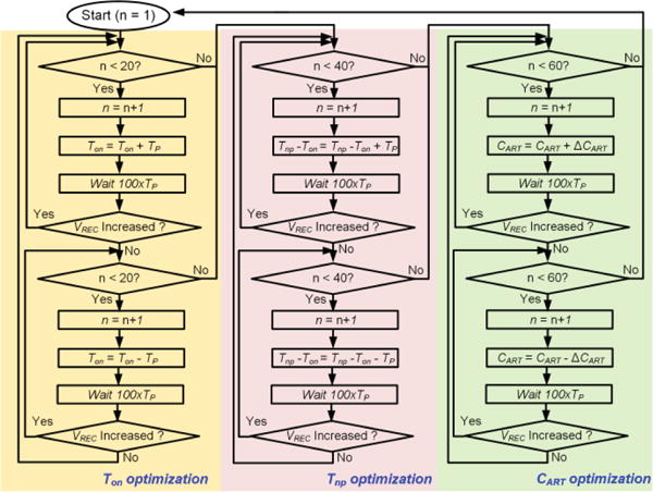
Flowchart of the control algorithm for multi-cycle Q-modulation with ART, which is implemented in the MCU of the current proof-of-concept prototype Rx module.
Fig. 9.
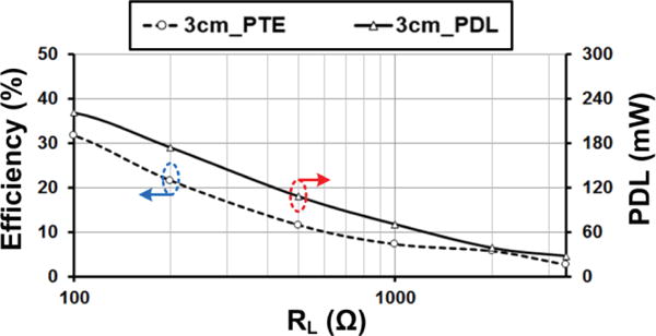
Measured PA + link efficiency and PDL in the 2-coil inductive link at d23 = 3 cm vs. loading variations from 100 Ω to 3.4 kΩ without multi-cycle Q-modulation.
V. Measurement Results
The proposed multi-cycle Q-modulation + ART techniques were verified by a small (1.5 × 1.8 cm2) proof-of-concept prototype Rx module made of COTS components for the experimental setup show in Fig. 10. The 5-bit capacitor bank, controlled by 5 NMOSs and an MSP430 MCU running the algorithm in Fig. 8, provides fine-tuning in parallel with the Rx series LC-tank, which can be considered as part of the resonance capacitor, C3 [40]. For instance, when SC is closed, the parallel capacitor bank and C3 are connected to the DC ground, and resonate at fp. The SC is controlled by the MCU to reduce the current from the L3C3-tank to the rectifier down to zero. This has the same effect as directly shorting the load in the theoretical model of Fig. 2 because the loading, RL, is defined as the resistive equivalent of all the power consumption following the rectifier.
Fig. 10.
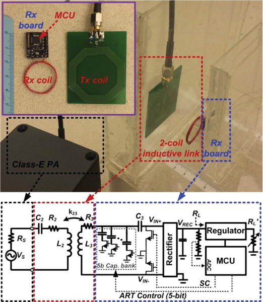
Experimental setup and block diagram of a simple proof-of-concept multi-cycle Q-modulation Rx prototype with ART (enclosed in the blue box).
Rectification following the LC-tank is provided by a full-wave low dropout Schottky diode bridge (BAS4002A). VREC is sampled and digitized by the MSP430 built in ADC through a resistive attenuator. To demonstrate the PA + link efficiency dependence on the load with and without multi-cycle Q-modulation, the 7.4 mW power consumption of in the MCU is excluded from this measurement. As shown in Fig. 10 schematic, RL in these measurements is the equivalent resistance following the rectifier, calculated from VREC / IREC, where IREC is the average current out of the full-wave rectifier. In order to set RL at a desired value, besides the MCU and regulator internal power consumption, which are relatively constant, an additional variable resistance, RL′, was added to the Rx board and its value was swept from 110 Ω to 27 kΩ.
Fig. 11 shows the measured transient waveforms of VREC, VIN+, VIN−, and SC in Fig. 10 with and without the proposed multi-cycle Q-modulation algorithm in Fig. 8, when RL = 500 Ω and d23 = 3 cm. It can be seen that the rectifier input voltages, VIN+ and VIN−, are boosted by Q-modulation, and VREC has increased significantly from an average of 2.61 V to 4.15 V with the same RF input source, VS, coil separation, and RL.
Fig. 11.
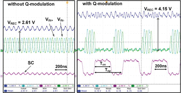
Measured transient waveforms of VREC, VIN+, VIN−, and SC in Fig. 8 without and with automatic multi-cycle Q-modulation at PVs,rms = 151 mW, fp = 13.56 MHz, RL = 500 Ω, and d23 = 3 cm.
To evaluate the performance of the multi-cycle Q-modulation and ART in terms of PA + link efficiency, ηQmod, six conditions were tested in Fig. 10 setup: 1) manual tuning without Q-modulation, 2) deliberate 4 pF detuning of C3′ without Q-modulation, 3) ART without Q-modulation, 4) manual tuning with Q-modulation, 5) automatic Q-modulation, and 6) ART + automatic Q-modulation, using the algorithm in Fig. 8. Figs. 12a and 12b show the results of these measurements vs. RL at d23 = 3 cm and vs. d23 at RL = 500 Ω, respectively. The PA + link efficiency was calculated by measuring the input power from the source and input power before the rectifier, considering the rectifier efficiency from the datasheet. The results show that the proposed multi-cycle Q-modulation has significantly increased ηQmod over a wide range of RL and d23, which are two parameters that often change during WPT in operation. For instance, in Fig. 12a, the multi-cycle Q-modulation with manual tuning has increased ηQmod from 7.2% to 18.1% at RL = 1 kΩ and d23 = 3 cm. Similarly, in Fig. 12b, the multi-cycle Q-modulation has improved ηQmod from 20.4% to 34.0% at d23 = 2.5 cm and RL = 500 Ω.
Fig. 12.
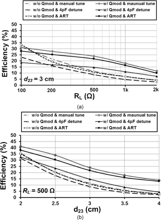
Measured results of PA + link efficiency in 6 different conditions: with and without Q-modulation and manual tuning, with and without Q-modulation and 4 pF detuning of the Rx LC-tank, without Q modulation but with ART, and with both automatic Q-modulation and ART. (a) ηQmod vs. load at d23 = 3 cm, and (b) ηQmod vs. distance at RL = 500 Ω.
The fully automated multi-cycle Q-modulation and ART show a slightly lower efficiency than the externally controlled Q-modulation, because Ton, Tnp−Ton, and CART fluctuate due to their continuous up/down search around their optimal values, according to the algorithm in Fig. 8. The 4 pF detuning degrades ηQmod with Q-modulation more than a conventional 2-coil link, as discussed in Fig. 7, because of the higher Q-factor in the former link. However, the ART can successfully compensate for detuning of C3′ to achieve the highest ηQmod close to manual tuning. Figs. 12a and 12b also show that the ART operation with and without the multi-cycle Q-modulation at RL = 500 Ω and d23 = 3 cm improves the efficiency by 1.9 % and 7.1 % for a 4 pF detuning of C3′, respectively. The measurement results demonstrate that the effect of the ART operation with the multi-cycle Q-modulation in the 2-coil inductive link is advantageous compared to the same condition without multi-cycle Q-modulation, which can also be seen in Fig. 7. In this experiment, the maximum PDL was 168.1 mW at RL = 100 Ω when VREC = 4.1 V.
Fig. 13 shows the measured transient waveforms of VREC, VIN+, VIN−, and SC with automatic multi-cycle Q-modulation and ART when the load suddenly changes from RL = 500 Ω to RL = 250 Ω at d23 = 3 cm. VREC suddenly drop from 4.22 V to 3.33 V due to higher current demand. Fig. 8 algorithm in the MSP430 tries to find a new optimal Ton and Tnp combination that would be a batter match for the new loading, and as a result, recovers part of VREC drop to stabilize at 3.78 V. The zoomed-in segments at the bottom of Fig. 13 shows that at steady state, Ton and Tnp have changed from 258 ns and 437 ns for RL = 500 Ω to 191 ns and 371 ns for RL = 250 Ω, respectively.
Fig. 13.
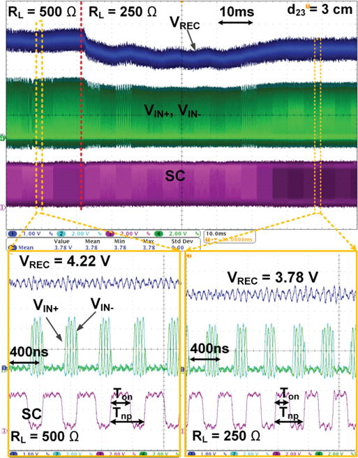
Measured transient waveforms of VREC, VIN+, VIN−, and SC with automatic multi-cycle Q-modulation and ART for sudden load variation from RL = 500 Ω to 250 Ω at d23 = 3 cm. The algorithm in Fig. 8 finds new optimal Ton and Tnp to maximize ηQmod for the new load condition, and as a result Ton and Tnp change from 258 ns and 437 ns to 191 ns and 371 ns, respectively.
VI. Conclusions
We have presented a new multi-cycle Q-modulation method, which can maintain the high PTE in wirelessly powered applications that operate in dynamic environments with motion and variable loading, such as implantable medical devices. The proposed multi-cycle Q-modulation circuit can be easily implemented on the Rx side of conventional 2-coil links either in the form of an ASIC or using COTS components, without any complex circuity or fast switching operation, needed in the conventional Q-modulation technique. Moreover, the proposed technique does not need sophisticated synchronization between the power carrier and Q-modulation switching signals, which facilitate its applicability to wireless links with higher power carrier frequencies. We have also demonstrated usage of the ART along with the new multi-cycle Q-modulation to dynamically maintain the PTE of the inductive link at its peak in the presence of disturbance in the surrounding environment or manufacturing process variations, which can otherwise significantly degrade the PTE by detuning the Rx LC-tank. Thanks to their simplicity, these methods can be extended to a wide variety of applications, utilizing the 2-coil inductive links in wide ranges of loading, separation, misalignment, and environmental variations.
Acknowledgments
This work was supported in part by the National Institutes of Health awards 5R21EB009437, R42NS055430, and the National Science Foundation awards ECCS-1408318 and IIP-1346416.
Biographies

Byunghun Lee (S’11) received the B.S. degree from Korea University, Seoul, South Korea, and the M.S. degree from Korea Advanced Institute of Technology (KAIST), Daejeon, South Korea, in 2008 and 2010, respectively.
From 2010 to 2011, he worked on wireless power transfer systems at KAIST as a design engineer. He is currently pursuing his Ph.D. degree in Electrical and Computer Engineering at Georgia Institute of Technology. His research interests include analog/mixed-signal IC design and wireless power/data transfer systems for biomedical applications.

Pyungwoo Yeon (S’14) received the B.Sc. degree in electrical and computer engineering from Seoul National University, Seoul, Korea, in 2010, and the M.S. degree in electrical engineering and information systems from the University of Tokyo, Tokyo, Japan, in 2012.
From February 2012 to May 2014, he worked as an analog IC designer at Samsung Electronics, Yongin, Korea, designing wireless power receiver IC for mobile devices. He is now pursuing his doctoral degree in the electrical and computer engineering at Georgia Institute of Technology and working on developing wirelessly powered implantable biomedical system at the GT-Bionics Lab. His research interests include analog/mixed-signal integrated circuit design, wireless power/data transfer, energy harvesting, and biomedical/implantable system design.

Maysam Ghovanloo (S’00–M’04–SM’10) received the B.S. degree in electrical engineering from the University of Tehran in 1994, the M.S. degree in biomedical engineering from the Amirkabir University of Technology in 1997, and the M.S. and Ph.D. degrees in electrical engineering from the University of Michigan in 2003 and 2004, respectively. From 2004 to 2007, he was an Assistant Professor at NC-State University, Raleigh, NC. He joined Georgia Institute of Technology, Atlanta, GA in 2007, where he is an Associate Professor and the Founding Director of the GT-Bionics Lab. He has authored or coauthored more than 200 peer-reviewed publications.
Dr. Ghovanloo is an Associate Editor of the IEEE TRANSACTIONS ON BIOMEDICAL ENGINEERING and IEEE TRANSACTIONS ON BIOMEDICAL CIRCUITS AND SYSTEMS. He was the chair of the 2015 IEEE Biomedical Circuits and Systems Conference in Atlanta, GA, and a member of the IEEE CAS Distinguished Lecture Program in 2015–16.
Contributor Information
Byunghun Lee, GT-Bionics lab, School of Electrical and Computer Engineering at the Georgia Institute of Technology, Atlanta, GA 30308, USA.
Pyungwoo Yeon, GT-Bionics lab, School of Electrical and Computer Engineering at the Georgia Institute of Technology, Atlanta, GA 30308, USA.
Maysam Ghovanloo, GT-Bionics lab, School of Electrical and Computer Engineering at the Georgia Institute of Technology, Atlanta, GA 30308, USA.
References
- 1.Finkenzeller K. RFID-Handbook. 2nd. Hoboken, NJ: Wiley; 2003. [Google Scholar]
- 2.Chwei-Sen Wang, Stielau Oskar H, Covic Grant A. Design considerations for a contactless electric vehicle battery charger. IEEE Trans Ind Electron. 2005 Oct;52(5):1308–1314. [Google Scholar]
- 3.Huh J, Lee SW, Lee WY, Cho GH, Rim CT. Narrow-width inductive power transfer system for online electrical vehicles. IEEE Trans Power Electron. 2011 Dec;26(12):3666–3679. [Google Scholar]
- 4.Zhang W, White JC, Mi CC. Loosely coupled transformer structure and iteroperability study for EV wireless charging systems. IEEE Trans Power Electron. doi: 10.1109/TPEL.2015.2433678. [DOI] [Google Scholar]
- 5.Pinuela M, Yates DC, Lucyszyn S, Mitcheson PD. Maximizing DC-to-load efficiency for inductive power transfer. IEEE Trans Power Electron. 2013 May;28(5):2437–2447. [Google Scholar]
- 6.Elliott GAJ, Covic GA, Kacprzak D, Boys JT. A New concept: Asymmetrical pick-ups for inductively coupled power transfer monorail systems. IEEE Trans Magn. 2006 Oct;42(10):3389–3391. [Google Scholar]
- 7.Covic GA, Boys JT, Kissin MLG, Lu HG. A three-phase inductive power transfer system for roadway-powered vehicles. IEEE Trans Ind Electron. 2007 Dec;54(6):3370–3377. [Google Scholar]
- 8.Kissin MLG, Boys JT, Covic GA. Interphase mutual inductance in polyphase inductive power transfer systems. IEEE Trans Ind Electron. 2009 Jul;56(7):2393–2400. [Google Scholar]
- 9.Moh K-G, Neri F, Moon S, Yeon P, Yu J, Cheon Y, Roh Y-S, Ko M, Park B-H. A fully integrated 6W wireless power receiver operating at 6.78MHz with magnetic resonance coupling. IEEE Intl Solid-State Cir Conf. 2015 Feb;:230–231. [Google Scholar]
- 10.Jung LH, Shany N, Emperle A, Lehmann T, Preston PB, Lovell NH, Suaning GJ. Design of safe two-wire interface-driven chip-scale neurostimulator for visual prosthesis. IEEE J Solid-State Circuits. 2013 Sep;48(9):2217–2229. [Google Scholar]
- 11.Lazzi G. Thermal effects of bioimplants. IEEE Eng Med Biol Mag. 2005 Sep-Oct;24(5):75–81. doi: 10.1109/memb.2005.1511503. [DOI] [PubMed] [Google Scholar]
- 12.Sodagar A, Perlin G, Yao Y, Najafi K, Wise K. An implantable 64-channel wireless microsystem for single-unit neural recording. IEEE J Solid-State Circuits. 2009 Sep;44(9):2591–2604. [Google Scholar]
- 13.Lee SB, Lee B, Kiani M, Mahmoudi B, Gross R, Ghovanloo M. An inductively-powered wireless neural recording system with a charge sampling analog front-end. IEEE Sensors J. 2016 Jan;16(2):475–484. doi: 10.1109/JSEN.2015.2483747. [DOI] [PMC free article] [PubMed] [Google Scholar]
- 14.Biederman W, Yeager D, Narevsky N, Koralek A, Carmena J, Alon E, Rabaey J. A fully-integrated, miniaturized (0.125 mm2) 10.5 μW wireless neural sensor. IEEE J Solid-State Circuits. 2013 Apr;48(4):960–970. [Google Scholar]
- 15.Muller R, Le HP, Li W, Ledochowitsch P, Gambini S, Bjorninen T, Koralek A, Carmena JM, Maharbiz MM, Alon E, Rabaey JM. A Minimally Invasive 64-Channel Wireless μECoG Implant. IEEE J Solid-State Circuits. 2015 Jan;50(1) [Google Scholar]
- 16.Liu W, Sivaprakasam M, Wang G, Zhou M, Granacki J, Lacoss J, Wills J. Implantable biomimetic microelectronic systems design. IEEE Eng Med Biol Mag. 2005 Sep-Oct;24:66–74. doi: 10.1109/memb.2005.1511502. [DOI] [PubMed] [Google Scholar]
- 17.Lee B, Kiani M, Ghovanloo M. A smart wirelessly-powered homecage for long-term high throughput behavioral experiments. IEEE Sensors J. 2015 Sep;15(9):4905–4916. doi: 10.1109/JSEN.2015.2430859. [DOI] [PMC free article] [PubMed] [Google Scholar]
- 18.Ahn D, Ghovanloo M. Optimal design of wireless power transmission links for millimeter-sized biomedical implants. IEEE Trans Biomed Circuits Syst. 2016 Feb;10(1):125–137. doi: 10.1109/TBCAS.2014.2370794. [DOI] [PubMed] [Google Scholar]
- 19.IEEE Standard for Safety Levels with Respect to Human Exposure to Radio Frequency Electromagnetic Fields, 3 kHz to 300 GHz, IEEE Standard C95.1, 1999.
- 20.Lazzi G. Thermal effects of bioimplants. IEEE Eng Med Biol Mag. 2005 Sep-Oct;24(5):75–81. doi: 10.1109/memb.2005.1511503. [DOI] [PubMed] [Google Scholar]
- 21.Liu W, Sivaprakasam M, Wang G, Zhou M, Granacki J, Lacoss J, Wills J. Implantable biomimetic microelectronic systems design. IEEE Eng Med Biol Mag. 2005 Sep-Oct;24:66–74. doi: 10.1109/memb.2005.1511502. [DOI] [PubMed] [Google Scholar]
- 22.Zargham M, Gulak PG. Maximum achievable efficiency in near-field coupled power-transfer systems. IEEE Trans Biomed Circuits Syst. 2012 Jun;6(3):228–245. doi: 10.1109/TBCAS.2011.2174794. [DOI] [PubMed] [Google Scholar]
- 23.RamRakhyani AK, Mirabbasi S, Chiao M. Design and optimization of resonance-based efficient wireless power delivery systems for biomedical implants. IEEE Trans Biomed Circuits Syst. 2011 Feb;5(1):48–63. doi: 10.1109/TBCAS.2010.2072782. [DOI] [PubMed] [Google Scholar]
- 24.Kurs A, Karalis A, Moffatt R, Joannopoulos JD, Fisher P, Soljacic M. Wireless power transfer via strongly coupled magnetic resonances. Science Express. 2007 Jul;317:83–86. doi: 10.1126/science.1143254. [DOI] [PubMed] [Google Scholar]
- 25.Kiani M, Jow U, Ghovanloo M. Design and optimization of a 3-coil inductive link for efficient wireless power transmission. IEEE Trans Biomed Circuits Syst. 2011 Dec;5(6):579–591. doi: 10.1109/TBCAS.2011.2158431. [DOI] [PMC free article] [PubMed] [Google Scholar]
- 26.Halpern ME, Ng DC. Optimal tuning of inductive wireless power links: limits of performance. IEEE Trans Circuits Syst I, Reg Papers. 2015 Mar;62(3):725–731. [Google Scholar]
- 27.Jow U-M, Ghovanloo M. Design and optimization of printed spiral coils for efficient transcutaneous inductive power transmission. IEEE Trans Biomed Circuits Syst. 2007 Sep;1(3):193–202. doi: 10.1109/TBCAS.2007.913130. [DOI] [PubMed] [Google Scholar]
- 28.Baker MW, Sarpeshkar R. Feedback analysis and design of RF power links for low-power bionic systems. IEEE Trans Biomed Circuits Syst. 2007 Mar;1(1):28–38. doi: 10.1109/TBCAS.2007.893180. [DOI] [PubMed] [Google Scholar]
- 29.Beh TC, Kato M, Imura T, Oh S, Hori Y. Automated impedance matching system for robust wireless power transfer via magnetic resonance coupling. IEEE Trans Ind Electron. 2013 Sep;60(9):3689–3698. [Google Scholar]
- 30.Xue R, Cheng K, Je M. High-efficiency wireless power transfer for biomedical implants by optimal resonant load transformation. IEEE Trans Biomed Circuits Syst. 2013 Apr;60:867–874. [Google Scholar]
- 31.Moriwaki Y, Imura T, Hori Y. Basic study on reduction of reflected power using DC/DC converters in wireless power transfer system via magnetic resonant coupling. IEEE Telecom Energy Conf. 2011:1–5. [Google Scholar]
- 32.Ahn D, Hong S. Wireless power transfer resonance coupling amplification by load-modulation switching controller. IEEE Trans Ind Electron. 2015 Feb;62(2):898–909. [Google Scholar]
- 33.Kiani M, Lee B, Yeon P, Ghovanloo M. A power management ASIC with Q-modulation capability for efficient inductive power transmission. IEEE Intl Solid-State Cir Conf. 2015 Feb;:226–227. doi: 10.1109/JSSC.2015.2453201. [DOI] [PMC free article] [PubMed] [Google Scholar]
- 34.Jow U, Ghovanloo M. Modeling and optimization of printed spiral coils in air, saline, and muscle tissue environments. IEEE Trans Biomed Circuits Syst. 2009 Oct;3(5):339–347. doi: 10.1109/TBCAS.2009.2025366. [DOI] [PMC free article] [PubMed] [Google Scholar]
- 35.Xu H, Bihr U, Becker J, Ortmanns M. A multi-channel neural stimulator with resonance compensated inductive receiver and closed loop smart power management. Proc of IEEE ISCAS. 2013 May;:638–641. [Google Scholar]
- 36.Si P, Hu AP, Malpas S, Budgett D. A frequency control method for regulating wireless power to implantable devices. IEEE Trans Biomed Circuits Syst. 2008 Mar;2(1):22–29. doi: 10.1109/TBCAS.2008.918284. [DOI] [PubMed] [Google Scholar]
- 37.Lee B, Kiani M, Ghovanloo M. A triple-loop inductive power transmission system for biomedical applications. IEEE Trans Biomed Circuits Syst. 2016 Feb;10(1):138–148. doi: 10.1109/TBCAS.2014.2376965. [DOI] [PubMed] [Google Scholar]
- 38.Lim Y, Tang H, Lim S, Park J. An adaptive impedance-matching network based on a novel capacitor matrix for wireless power transfer. IEEE Trans Power Electron. 2014 Aug;29(8):4403–4413. [Google Scholar]
- 39.Aldhaher S, Luk PC-K, Wihdborne JF. Electronic tuning of misaligened coils in wireless power transfer systems. IEEE Trans Power Electron. 2014 Nov;29(11):5975–5982. [Google Scholar]
- 40.RamRakhyani AK, Mirabbasi S, Chiao M. Design and optimization of resonance-based efficient wireless power delivery systems for biomedical implants. IEEE Trans Biomed Circuits Syst. 2011 Feb;5(1):48–63. doi: 10.1109/TBCAS.2010.2072782. [DOI] [PubMed] [Google Scholar]