

Abstract
An elastic membrane stretched between two walls takes a shape defined by its length and the volume of fluid it encloses. Many biological structures, such as cells, mitochondria and coiled DNA, have fine internal structure in which a membrane (or elastic member) is geometrically ‘confined’ by another object. Here, the two-dimensional shape of an elastic membrane in a ‘confining’ box is studied by introducing a repulsive confinement pressure that prevents the membrane from intersecting the wall. The stage is set by contrasting confined and unconfined solutions. Continuation methods are then used to compute response diagrams, from which we identify the particular membrane mechanics that generate mitochondria-like shapes. Large confinement pressures yield complex response diagrams with secondary bifurcations and multiple turning points where modal identities may change. Regions in parameter space where such behaviour occurs are then mapped.
Keywords: membranes, biological mechanics, interfaces, mitochondrion, bifurcation
1. Introduction
The mitochondrion is an organelle of the cell that is responsible for converting sugars into adenosine triphosphate (ATP) and is for good reason considered the ‘engine’ of the cell [1]. This double-membrane structure, shown in figure 1, consists of a permeable outer membrane, which allows transport of sugars into the intermembrane space, bounding an impermeable inner membrane where the production of ATP takes place. The efficiency with which a mitochondrion processes sugars is directly related to the surface area of the inner membrane, which can be anywhere from 4 to 10 times as large as the surface area of the outer membrane. The typical inner membrane has size 1 µm and is characterized by a bending rigidity α = 10−12 erg, tension β = 10−3 ∼ 10−1 pN nm−1 and internal pressure p = 4 × 10⁻² atm [2,3]. To accommodate such large surface areas, the inner membrane deforms itself into a series of sharp folds (invaginations) known as cristae. In addition to energy production, the structure of the inner membrane can affect specific chemical pathways and processes, such as cellular differentiation and the cell cycle, through its geometry. The mechanics governing the morphology of the inner membrane is our focus.
Figure 1.

Experimental image of a typical mitochondrion showing a large inner membrane confined by a smaller outer membrane. (Reproduced from Fawcett [1].) (Online version in colour.)
As shown in figure 1, the inner membrane behaves like a closed elastic sheet that deforms as a two-dimensional object. This sheet fits within the outer membrane and has three-dimensional aspects, but it is expected that the mechanics should be described well with a two-dimensional model. In this study, we develop a two-dimensional Cartesian model of a mitochondrion where we hold the outer membrane as a rigid confining surface and focus on the shape of the inner membrane. The inner membrane is characterized by a tension β that encloses a volume of fluid V (intermembrane space) with pressure p. The interactions between the inner membrane and outer membrane are modelled using a general confining pressure that prevents the inner membrane from penetrating the outer surface. Our idealized model for the observed confinement (outer membrane) geometry should reproduce the essential feature of the interaction, especially in the limiting case having a large number of folds.
Biological interfaces/membranes are subject to instabilities such as surface wrinkling, folding and creasing in the presence of (i) geometrical constraints (e.g. particles [4,5], fibres [6,7] and thin films [8]) or (ii) external loadings (e.g. mechanical forces [9], hydration stresses [10–12] or capillarity [13,14]). The review by Li et al. [15] catalogues the complex morphology of observed ‘surface instabilities’ that occur in soft biological materials and illustrates the relevance of such phenomena to industrial applications, such as soft lithography, flexible electronics and biomedical engineering. The transition from wrinkle to fold is seen upon increasing the membrane compression to a given threshold [16]. In unconfined geometries, the shape of surface wrinkles may be computed using any number of mathematical techniques, such as elastic rod theory or by considering a fluid–structure interaction problem of a periodic, length-preserving bilipid membrane modelled by the Helfrich energy immersed in a viscous fluid [17]. The latter technique has been used to simulate the flow of red blood cells [18]. Here, we use numerical continuation to compute membrane shapes [19].
Continuation methods allow one to ‘follow’ a solution to a given problem as a parameter changes. The method is well known in a number of different fields: astrophysics [20–22], vortex flows [23], capillary surfaces [24] and rigid body dynamics [25], but has yet to become popularized with elastic membranes to our knowledge. We use the method to mimic the mechanics of the inner membrane of the mitochondrion. In essence, we perform ‘numerical experiments’ and compare our predictions against experimental observations. We consider two scenarios. The first treats the mitochondrion as a ‘closed system’ with fixed fluid volume. We then calculate the membrane response (p, β) to increased length S. The second assumes the membrane tension is a material parameter (fixed) and the system is ‘open’ to allow fluid transport through the ‘intermembrane space’. It is clear from the comparison of our results that the second scenario most probably governs the mechanics of the inner membrane, whereas the first scenario is potentially relevant to other applications such as wrinkling [26] and folding [27,28] in elastic sheets.
From a broader mechanical perspective, the shape of elastic membranes belongs to a class of problems classically referred to as an ‘elastica’. Examples include, but are not limited to, vesicles whose shapes can be determined using analytical techniques [29,30] or numerical techniques such as the finite-element methods [31] or the discrete space variation method [32]. More recently, attention has been paid to solid elastic members geometrically constrained to lie within a rectangular [33] or circular channel [34]. Typical modelling of such situations involves introducing geometric pseudo-forces to account for the presence of the geometrical support [9,35]. Alternatively, one can introduce intermolecular forces, as done with the adhesion of elastic sheets [36], snap-through of graphene sheets onto complex substrate geometries [37], peeling of elastic sheets [38] and the pull-in instability of carbon nanotube tweezers [39].
An elastic member in contact with a fluid reservoir can deform from the associated fluid pressure, either hydrostatic or capillary. For hydrostatic pressures, the buckled shapes of thin elastic sheets have a closed-form solution [40,41] with post-buckling solutions numerically computed using continuation techniques [42]. For liquid interfaces endowed with surface tension, e.g. drops, capillary pressure and other wetting forces [43] give rise to ‘elastocapillary deformations’ with applications such as capillary origami [44], wrapping of droplets by elastic sheets [45] and the formation of wetting ridges [46].
The construction of the governing equations through a variational principle subject to auxiliary constraints has been well studied in related problems on capillary surfaces (membranes with negligible elastic resistance), whereby the stability of solutions to the Euler–Lagrange equations associated with the respective energy functional can be read off a preferred bifurcation diagram [24,47]. Although we do not discuss stability of solutions here, the relationship between these mathematical theorems and stability of the shapes predicted in this manuscript would certainly be of interest.
We begin this paper by formulating a mathematical model that describes the shape of an elastic membrane confined by two parallel surfaces by introducing a confinement pressure. Families of membrane shapes are computed according to two alternative representations for the mechanics of the inner membrane of the mitochondria. Response diagrams which plot the membrane tension and fluid pressure as functions of total arclength are computed. For large confinement pressures, the membrane response often exhibits secondary bifurcations (SBs) and multiple turning points where the membrane's modal identity may change. We catalogue the canonical behaviours and map the corresponding regions of parameter space. Our results predict membrane shapes close to observed morphologies of the inner membrane and provide insight into the governing mechanics. Finally, some concluding remarks are offered regarding the relevance of our model to experimental observation and the applicability of our methods to related problems.
2. Mathematical formulation
Consider an elastic membrane ∂D of length S held by tension β that encloses a domain D with volume of fluid per unit length V and pressure p, as shown in figure 2. The membrane shape h(x) is defined in Cartesian coordinates and ‘confined’ to lie within the domain bound by two rigid walls at y = ±H, with incompressible fluid of fixed volume above and below the interface. Our model can be viewed as an idealized mitochondrion by treating the solid wall as the outer membrane, the volume of fluid as the intermembrane space and the interface h as the inner membrane. The energetics of this configuration are described by the Helfrich [48,49] free energy functional
| 2.1 |
where κ and α are the curvature and bending rigidity of the membrane, respectively, and pc is a confinement pressure introduced to model the interactions between the membrane and bounding surfaces. Although referred to as tension herein, note that β > 0 corresponds to compressive forces. We are interested in membrane shapes on a periodic domain and therefore introduce a horizontal length scale L. Lengths are then scaled by L, while tension β and pressure p are scaled by the bending rigidity α;
 |
2.2 |
Figure 2.

Definition sketch. An interface ∂D with tension β and length S, defined in Cartesian coordinates y = h(x), encloses a domain D with volume V and pressure p that is confined between two solid walls at y = ±H. (Online version in colour.)
Herein, we drop the hats for simplicity.
The Euler–Lagrange equations for the functional (2.1) are given by
| 2.3 |
where Δ is the surface Laplacian [50] and we have introduced a general confinement pressure pc(h). We model the interactions between the membrane and the bounding solid using the power-law form,
| 2.4 |
whose magnitude is controlled by the parameter M. Here 2H is the wall spacing that defines confinement geometry, whereas the exponent n models the interaction, e.g. n = 3 for medium range van der Waals [36,37,51]. For simplicity, we set n = 1 and H = 1/2 unless otherwise stated. We choose the power-law form (2.4), because it is a ‘hard’ potential that prevents the membrane from penetrating the solid. It is straightforward to analyse other functional forms for the repulsive confinement pressure, such as the ‘soft’ potential for hydration stresses [12,52] (see appendix A).
The membrane equation (2.3) is coupled to an equation for the curvature κ = κ(h), written in Cartesian coordinates, which will be defined shortly. These governing equations are augmented by the following boundary conditions:
| 2.5 |
which are periodic conditions (with period 2L), where we have taken the symmetric extension about the midplane x = 0. Note that this is tantamount to setting the phase of the membrane shape. Finally, the integral conditions
| 2.6 |
fix the volume V of fluid and total arclength S of the membrane, respectively. Note that these are defined on the half-domain.
3. Results
The energy functional (2.1) can be viewed as a constrained variational principle provided one treats the tension β and pressure p as Lagrange multipliers (unknowns) that are fixed by the integral constraints on volume V and arclength S. Here, (β, S) and (p, A) are dual variables. One can consider the tension β and pressure p as known parameters, in which case V and S are solution measures. This dual construction lends itself to computational methods that involve continuation, whereby a known solution is ‘continued’ in one or more parameters to obtain families of solutions [53]. We use the continuation software package AUTO [19] to compute families of membrane shapes. With regard to the morphology of the inner membrane of the mitochondria, the strategy we employ is to perform ‘numerical experiments’ using continuation that represents the mechanics typical to the inner membrane.
3.1. Long-wave approximation
We begin by examining the long-wave limit  with curvature given by
  . In this limit, equation (2.3) becomes
| 3.1 |
For fixed V, the ‘unconfined’ (M = 0) solutions,
| 3.2 |
belong to the one-parameter family shown in the bifurcation diagram of figure 3a, which plots tension β against arclength S. Solution branches emanating from the trivial branch S = 1 are characterized by a wavenumber k and parametrized by arclength, as shown for the k = 1 solution in figure 3b. Note that the membrane tension is constant, regardless of the arclength. The response diagram illustrates the dual construction mentioned above: (i) traversing the graph horizontally for prescribed arclength S reveals the computed tension β (Lagrange multiplier), while (ii) traversing the graph vertically for fixed tension gives the arclength of that solution.
Figure 3.

Unconfined (M = 0) long-wave approximation: (a) bifurcation diagram plotting arclength S against tension β and (b) the family of solutions along the k = 1 branch. (Online version in colour.)
The response of a membrane in confinement (M ≠ 0) becomes more complicated, as shown in figure 4a for the branch k = 1. Here, we compute the response diagram for fixed V = 0.5 by continuing in S from the trivial state h = 0 and contrasting against the unconfined (M = 0) response. Both confined and unconfined branches bifurcate from the trivial branch at β = π2 and, upon increasing S, the membrane in confinement responds by increasing its tension (stiffening) in order to accommodate the additional membrane length. The corresponding membrane shape tends to steepen on the sides and hug the bounding surface when compared with the limiting unconfined solution that obeys the geometrical constraint, as shown in figure 4b.
Figure 4.

Confined (M = 0.1) long-wave approximation: (a) response diagram for the k = 1 solution in the long-wave approximation exhibits membrane stiffening upon an increase in length S compared with the unconfined (dashed) solution. (b) Membrane shapes at points A and B illustrate the effect of the confinement pressure. Here V = 0.5, M = 0.1. (Online version in colour.)
3.2. Full model
The governing membrane equation (2.3) is coupled to the nonlinear curvature
 |
3.3 |
Recall that we have used Cartesian coordinates for convenience to simply analyse the confinement pressure and avoid self-intersecting shapes. This construction ensures single-valued functions h(x). As mentioned above, we use continuation methods to solve the nonlinear problem in order to better understand the mechanics of the inner membrane by comparing our predictions against observed morphologies. We explore two possible scenarios: (i) fixed V and (ii) fixed β. In the first case, we fix V and use S as the principal continuation parameter, adjusting the tension and pressure accordingly. That is, we study how the membrane responds (p, β) as more arclength is packed between the two ‘outer membranes’. By contrast, for fixed β we vary p and observe V and S for each (p, β). The two alternatives highlight the dual construction of the variational principle.
3.2.1. Prescribed fluid volume
Figure 5a plots the response diagram β−S for fixed V = 0.5 with confining pressure magnitude M = 0.1. Note that the membrane initially responds by slightly decreasing its tension (softening) as arclength increases, which is different from the long-wave model of figure 4a. We attribute this feature to the nonlinear terms in the model which allows for high local stress to be balanced by the confinement pressure terms instead of surface tension. As arclength increases further the membrane begins to feel the bounding surface and responds by increasing its tension. For the mode k = 2, the tension dramatically increases from 25 to 160 despite a marginal increase in arclength. Limiting cases of membrane shapes with the largest arclength on the respective branches are shown in figure 5b. Our computational approach did not find solutions past these values of β, which is not surprising given the large curvatures and steep sides observed in figure 5b. Note the steep sides reminiscent of the inner membrane shapes in figure 1.
Figure 5.

(a) Bifurcation diagram plotting arclength S against tension β and (b) membrane shapes with wavenumbers k = 1, 2, 5 at points A, B, C of part (a) for M = 0.1, V = 0.5. (Online version in colour.)
Continuation methods also allow one to ‘continue’ different solution measures, such as the bifurcation points shown in figure 5a, in a given parameter. Figure 6 plots the locus of bifurcation points in different parameters; (a) confinement pressure M, (b) V and (c) p. Interestingly, for large confinement pressure M the order in which membrane shapes appear can become distorted. For example, traversing the graph by increasing tension β for fixed M = 1 intersects (in order) the k = 1, 2, 3 branches, whereas for M = 80 the order becomes distorted k = 2, 1, 3; the k = 2 shape appears before the k = 1 shape. We attribute this feature to the strong interactions with the solid surface through the nonlinearity of the confinement pressure.
Figure 6.

The locus of bifurcation points computed by continuation in the (a) confinement force M for V = 0.5, (b) volume V and (c) pressure p with M = 0.1. (Online version in colour.)
Along the same lines, the locus of bifurcation points in the volume V space reveals that starting from the neutral state V = 0.5 the membrane dramatically increases its tension and pressure as V is removed. Note the symmetry for increasing volume V from the neutral state. With regard to the mitochondrion, large pressures and tensions may be expected to result in rupture of the inner membrane under such circumstances. As such, figure 6b could be viewed as a guide in controlling the hydration (equivalently, V) or p to ensure the membrane tension remains below a critical rupture threshold. As with the confinement pressure M, spectral reordering may occur when the membrane strongly feels the presence of the confining surface.
In general, the membrane response becomes more complex with increasing M, as shown in figure 7a which plots β against S for M = 1. Initially, for increasing S, the membrane responds by softening (β decreasing) until the first limit point (LP), defined by the appearance of two solutions, is traversed, after which the membrane stiffens (β increasing) until the second LP, whereby the membrane changes its modal identity from k = 1 to 3, after which it continues to soften. Our continuation method allows us to follow the second LP, thereby constructing the curve in the β−M parameter space where the modal identity changes. The locus of LPs shown in figure 7b is a non-monotonic curve that could not have been predicted either a priori or by long-wave theory. Needless to say, cataloging membrane shapes for large M becomes increasingly difficult.
Figure 7.
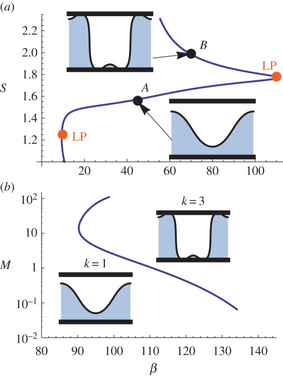
(a) Response diagram for a membrane subject to strong confinement forces M = 1 exhibits two turning (LP) points. Increasing the arclength S along the branch shows the wavenumber identity changes from k = 1 (A) to k = 3 (B) as the second fold is traversed. (b) The locus of LPs is continued in the M − β space. Representative shapes are shown as insets. (Online version in colour.)
SBs off the primary branch are typical for larger values of M. Figure 8a plots the response diagram that exhibits an SB off the primary branch k = 2 for M = 0.25 and V = 0.5. Solutions on the secondary branch preserve the modal identity k = 2, but exhibit a different symmetry. Both solutions are symmetric about the centre line x = 0. However, solutions on the primary branch are also symmetric about the vertical generator x = 1/2, while solutions on the secondary branch are not. The locus of SB points for the branch k = 2 are shown in figure 8b in the β−M parameter space. As could be expected, larger confinement pressures M lead to increased membrane tension β. The classification of the space of membrane shapes can become quite complex, as there are three equivalent membrane shapes for β = 30. The question of which membrane shape occurs in the mitochondrion may depend upon the loading path and can only be answered by stability analysis, which is outside the scope of this paper.
Figure 8.

(a) Bifurcation (BP) off the k = 2 primary branch for M = 0.25 exhibits solutions that preserve wavenumber identity, but have different symmetry. (b) The locus of SBs is continued in the M−β space. (Online version in colour.)
3.2.2. Prescribed membrane tension
The second scenario we consider is one where the membrane tension β is fixed and the pressure p is allowed to vary. As stated earlier, in this case the volume and arclength are solution measures, β, p are known material parameters. The response diagram of figure 9a plots the pressure p against arclength S for fixed β = 10. As shown, the pressure dramatically increases with the arclength due to the strong interactions between the membrane and confining surface; a large fraction of the membrane shape lies near the idealized ‘outer membrane’. The limiting case corresponds to a total arclength S ≈ 2.84, which is nearly 95% of the length S = 3 of the confining slot geometry with H = 0.5. Figure 9b plots the volume V against arclength S to show volume is removed as pressure increases. The limiting case has volume V ≈ 0.058. The morphology of the membrane shape shown in figure 9a (inset) closely resembles the inner membrane of the mitochondrion observed in the literature (figure 1), leading us to believe that one should treat the membrane tension as a known material parameter. In addition, our computed shapes qualitatively resemble those computed by Guo & Li [32], who introduce a repulsive intermembrane potential (disjoining pressure) to model self-avoiding behaviour and prevent membrane self-intersection. Note that our shapes are non-intersecting via construction in Cartesian coordinates.
Figure 9.

(a) Response diagram plotting pressure p against arclength S with limiting membrane shape inset and (b) parametric plot of volume V against arclength S for fixed tension β = 10 and M = 0.001. (Online version in colour.)
3.3. Biological interpretation
We revisit our results to interpret the biological mechanics of the inner membrane of the mitochondrion. The first scenario could be idealized as a ‘closed system’ in which the fluid volume V is fixed and the membrane responds (p, β) to increasing length S. Note that our computed membrane tensions β in figures 5a, 6 and 8 are all consistent with observed values for the mitochondrion  (see the Introduction) [2,3]. Figure 7 shows the response can be complex; the membrane initially softens, followed by a period of stiffening and then softens again after changing its wavenumber character. In this case, the membrane tension must actively change throughout the process and this must be accomplished through the chemistry of the lipid bilayer. Although it is well known that biochemical processes can be complex, this scenario seems unlikely.
By contrast, the second scenario, where the membrane tension is treated as a material parameter, can be idealized as an ‘open system’ that allows for fluid transport through the ‘intermembrane space’. Our results predict membrane shapes that closely resemble the morphology of the mitochondrion (figure 9). Additionally, the limiting case has a large pressure p ∼ 104 whose order is consistent with experimental observations [2,3] ( calculated from the numerical values given in the Introduction). These two observations strongly suggest that the inner membrane obeys the mechanics of the second scenario.
4. Concluding remarks
We have developed an idealized model of an elastic membrane in confinement in order gain insight into the mechanics of the inner membrane of the mitochondrion, a double-membrane structure, whose outer membrane acts as a confining surface. The governing equations are derived from a constrained variational principle that has a dual interpretation that we exploit to perform ‘numerical experiments’ that replicate typical mechanics that may lead to the unique morphology of the inner membrane. Recall that we have chosen to use a Cartesian representation to avoid self-intersecting shapes, which restricts the class of allowable functions. For example, shapes with a bulbous tip are not allowed here but would be in an arclength parametrization. This construction could affect the response diagrams (e.g. figures 5a and 7a). We compute the bifurcation diagrams using the continuation software AUTO to show how the membrane's tension and associated fluid pressure p respond to increases in total arclength. For small confinement pressures, the membrane initially softens as its length grows until it feels the presence of the confining surface, after which the membrane stiffens significantly in order to accommodate additional length (figure 5a). As the confinement pressure M increases, the membrane response can become complex, often exhibiting multiple turning points and SBs (cf. figures 7 and 8). Our work has catalogued such behaviour and mapped corresponding regions in parameter space.
Our results indicate that treating the membrane tension β as a material parameter in an ‘open system’ that allows for fluid transport through the ‘intermembrane space’ yields membrane shapes that compare favourably with observed morphologies, thereby generating insight into the mechanics of the inner membrane. This interpretation is consistent with the mechanism by which the mitochondrion controls the transport of sugars across the outer membrane into the intermembrane space to be processed by the inner membrane. Clearly, it is crucial to include the fluid mechanics of the transport process in developing future models of the mitochondrion. For example, how does dehydration or rehydration affect the efficiency with which the mitochondrion can process sugars into ATP?
From a mathematical perspective, we hope our results show that the application of continuation methods, which are typically applied to problems on capillary surfaces, can be used on related problems involving elastic membranes. Although we do not focus on stability issues here, the constrained variational structures inherent in problems on elastic membranes are well suited to bifurcation theoretic approaches, such as the Poincaré–Maddocks turning point theorems [54].
Extensions to our model will involve changing the geometry of the confining surface to better reflect the outer membrane of the mitochondria or increasing the degree of freedom in the model by treating the confining surface as a deformable membrane, whose shape must also be determined as part of the problem solution. Along a similar thread, there are many problems in biological mechanics that involve biological members ‘confined’ by some geometry, such as DNA coiling, that may be applicable to our general solution procedure. Perhaps the most direct extension would be to consider the three-dimensional case; this is non-trivial and involves solving a complicated partial differential equation associated with the free boundary value problem.
Acknowledgements
We wish to thank Alejandro Sanchez, who did some of the initial calculations presented in appendix A. We also would like to thank Jeff McFadden for several helpful conversations.
Appendix A. Hydration stresses
It is straightforward to analyse a membrane in the presence of a confinement pressure resulting from hydration stresses [12,52],
| A 1 |
by substituting into equation (2.3). Here λ is a characteristic length scale over which the hydration forces act. Repulsive hydration forces have been observed experimentally by Israelachvili & McGuiggan [55] and Leikin et al. [56]. Equation (A 1) can be viewed as a ‘soft’ potential whose magnitude remains finite as the membrane touches the solid support. By contrast, the hard potential (2.4) used in the main text gives rise to infinite forces as the membrane approaches the solid that prevents penetration into the solid.
Figure 10 plots the bifurcation diagram S against β in the long-wave limit for a membrane in the presence of hydration stresses. Note that the response diagram is qualitatively similar to that reported in figure 7 for the hard potential (2.4), with the exception that the membrane intersects the solid for these values of the parameters M, λ (see inset figure 10). That is, these computed membrane shapes do not physically represent the observed mitochondrion shapes that we seek to model. For the soft potential (A 1), there is a pseudo-support at some distance away from the actual solid, whose position cannot be predicted a priori. In figure 11, we plot the membrane shape for fixed arclength S = 3, as a function of λ, to show that the location of the pseudo-support depends strongly on (i) λ and (ii) the wavenumber k. For fixed λ, the k = 2 shapes may not intersect the solid while the k = 1 shapes may do so. Whether or not this occurs is not predictable a priori and it is primarily for this reason that we consider the hard potential (2.4) in this paper.
Figure 10.

Response diagram in the long-wave limit for a membrane in the presence of hydration stresses M = 10, λ = 10−2 by plotting arclength S against tension β. The membrane shape (inset) for S = 3 penetrates the solid for this set of parameters, which is indicative of a soft potential. (Online version in colour.)
Figure 11.

Membrane shapes (k = 1, 2) in the long-wave limit in the presence of hydration stresses with M = 10 for fixed arclength S = 3, as it depends upon the characteristic length λ, penetrate the solid for certain values of λ which cannot be predicted a priori. (Online version in colour.)
Authors' contributions
J.B.B., M.J.M. and S.H.D. conceived the study and wrote and revised the manuscript. J.B.B. performed the analysis and simulations. All authors gave final approval for publication.
Competing interests
We declare we have no competing interests.
Funding
M.J.M. acknowledges partial support from NSF grant no. DMS-1312935.
References
- 1.Fawcett D. 1981. The cell. Philadelphia, PA: W. B. Saunders Co. [Google Scholar]
- 2.Bo L, Waugh RE. 1989. Determination of bilayer membrane bending stiffness by tether formation from giant, thin-walled vesicles. Biophys. J. 55, 509–517. ( 10.1016/S0006-3495(89)82844-9) [DOI] [PMC free article] [PubMed] [Google Scholar]
- 3.Ghochani M, Nulton J, Salamon P, Frey T, Rabinovitch A, Baljon A. 2010. Tensile forces and shape entropy explain observed crista structure in mitochondria. Biophys. J. 99, 3244–3254. ( 10.1016/j.bpj.2010.09.038) [DOI] [PMC free article] [PubMed] [Google Scholar]
- 4.Vella D, Mahadevan L. 2005. The ‘Cheerios effect’. Am. J. Phys. 73, 817–825. ( 10.1119/1.1898523) [DOI] [Google Scholar]
- 5.Vella D. 2015. Floating versus sinking. Annu. Rev. Fluid Mech. 47, 115–135. ( 10.1146/annurev-fluid-010814-014627) [DOI] [Google Scholar]
- 6.Evans AA, Spagnolie SE, Bartolo D, Lauga E. 2013. Elastocapillary self-folding: buckling, wrinkling, and collapse of floating filaments. Soft Matter 9, 1711–1720. ( 10.1039/C2SM27089G) [DOI] [Google Scholar]
- 7.Duprat C, Protiere S, Beebe A, Stone H. 2012. Wetting of flexible fibre arrays. Nature 482, 510–513. ( 10.1038/nature10779) [DOI] [PubMed] [Google Scholar]
- 8.Schroll R, Adda-Bedia M, Cerda E, Huang J, Menon N, Russell T, Toga K, Vella D, Davidovitch B. 2013. Capillary deformations of bendable films. Phys. Rev. Lett. 111, 014301 ( 10.1103/PhysRevLett.111.014301) [DOI] [PubMed] [Google Scholar]
- 9.Domokos G, Holmes P, Royce B. 1997. Constrained Euler buckling. J. Nonlinear Sci. 7, 281–314. ( 10.1007/BF02678090) [DOI] [Google Scholar]
- 10.Mora T, Boudaoud A. 2006. Buckling of swelling gels. Eur. Phys. J. E 20, 119–124. ( 10.1140/epje/i2005-10124-5) [DOI] [PubMed] [Google Scholar]
- 11.Barros W, de Azevedo EN, Engelsberg M. 2012. Surface pattern formation in a swelling gel. Soft Matter 8, 8511–8516. ( 10.1039/c2sm25617g) [DOI] [Google Scholar]
- 12.Blount MJ, Miksis MJ, Davis SH. 2015. Fluid flow beneath a semipermeable membrane during drying processes. Phys. Rev. E 85, 016330 ( 10.1103/PhysRevE.85.016330) [DOI] [PubMed] [Google Scholar]
- 13.Bostwick JB, Daniels KE. 2013. Capillary fracture of soft gels. Phys. Rev. E 88, 042410 ( 10.1103/PhysRevE.88.042410) [DOI] [PubMed] [Google Scholar]
- 14.Daniels KE, Mukhopadhyay S, Houseworth PJ, Behringer RP. 2007. Instabilities in droplets spreading on gels. Phys. Rev. Lett. 99, 124501 ( 10.1103/PhysRevLett.99.124501) [DOI] [PubMed] [Google Scholar]
- 15.Li B, Cao Y-P, Feng X-Q, Gao H. 2012. Mechanics of morphological instabilities and surface wrinkling in soft materials: a review. Soft Matter 8, 5728–5745. ( 10.1039/c2sm00011c) [DOI] [Google Scholar]
- 16.Pocivavsek L, Dellsy R, Kern A, Johnson S, Lin B, Lee KYC, Cerda E. 2008. Stress and fold localization in thin elastic membranes. Science 320, 912–916. ( 10.1126/science.1154069) [DOI] [PubMed] [Google Scholar]
- 17.Marple GR, Purohit PK, Veerapaneni S. 2015. Equilibrium shapes of planar elastic membranes. Phys. Rev. E 92, 012405 ( 10.1103/PhysRevE.92.012405) [DOI] [PubMed] [Google Scholar]
- 18.Freund JB. 2014. Numerical simulation of flowing blood cells. Annu. Rev. Fluid Mech. 46, 67–95. ( 10.1146/annurev-fluid-010313-141349) [DOI] [Google Scholar]
- 19.Doedel EJ, Fairgrieve TF, Sandstede B, Champneys AR, Kuznetsov YA, Wang X.2007. AUTO-07P: Continuation and bifurcation software for ordinary differential equations. http://indy.cs.concordia.ca/auto/ .
- 20.Lynden-Bell D, Wood R. 1968. The Gravo-thermal catastrophe in isothermal spheres and the onset of red-giant structure for stellar systems. Mon. Not. R. Astron. Soc. 138, 495–525. ( 10.1093/mnras/138.4.495) [DOI] [Google Scholar]
- 21.Katz J. 1978. On the number of unstable modes of an equilibrium. Mon. Not. R. Astron. Soc. 183, 765–770. ( 10.1093/mnras/183.4.765) [DOI] [Google Scholar]
- 22.Katz J. 1979. On the number of unstable modes of an equilibrium—II. Mon. Not. R. Astron. Soc. 189, 817–822. ( 10.1093/mnras/189.4.817) [DOI] [Google Scholar]
- 23.Luzzatto-Fegiz P, Williamson CHK. 2012. Determining the stability of steady two-dimensional flows through imperfect velocity-impulse diagrams. J. Fluid Mech. 706, 323–350. ( 10.1017/jfm.2012.255) [DOI] [Google Scholar]
- 24.Lowry BJ, Steen PH. 1995. Capillary surfaces: stability from families of equilibria with application to the liquid bridge. Proc. R. Soc. Lond. A 449, 411–439. ( 10.1098/rspa.1995.0051) [DOI] [Google Scholar]
- 25.Maddocks JH. 1991. On the stability of relative equilibria. IMA J. Appl. Math. 46, 71–99. ( 10.1093/imamat/46.1-2.71) [DOI] [Google Scholar]
- 26.Cerda E, Mahadevan L. 2003. Geometry and physics of wrinkling. Phys. Rev. Lett. 90, 074302 ( 10.1103/PhysRevLett.90.074302) [DOI] [PubMed] [Google Scholar]
- 27.Brau F, Damman P, Diamant H, Witten TA. 2013. Wrinkle to fold transition: influence of the substrate response. Soft Matter. 9, 8177–8186. ( 10.1039/c3sm50655j) [DOI] [Google Scholar]
- 28.Démery V, Davidovitch B, Santangelo CD. 2014. Mechanics of large folds in thin interfacial films. Phys. Rev. E 90, 042401 ( 10.1103/PhysRevE.90.042401) [DOI] [PubMed] [Google Scholar]
- 29.Veerapaneni SK, Raj R, Biros G, Purohit PK. 2009. Analytical and numerical solutions for shapes of quiescent two-dimensional vesicles. Int. J. NonLinear Mech. 44, 257–262. ( 10.1016/j.ijnonlinmec.2008.10.004) [DOI] [Google Scholar]
- 30.Giomi L. 2013. Softly constrained films. Soft Matter 9, 8121–8139. ( 10.1039/c3sm50484k) [DOI] [Google Scholar]
- 31.Kahraman O, Stoop N, Müller MM. 2012. Fluid membrane vesicles in confinement. New J. Phys. 14, 095021 ( 10.1088/1367-2630/14/9/095021) [DOI] [Google Scholar]
- 32.Guo K, Li J. 2011. Exploration of the shapes of double-walled vesicles with a confined inner membrane. J. Phys. 23, 285103 ( 10.1088/0953-8984/23/28/285103) [DOI] [PubMed] [Google Scholar]
- 33.Roman B, Pocheau A. 2002. Postbuckling of bilaterally constrained rectangular thin plates. J. Mech. Phys. Solids 50, 2379–2401. ( 10.1016/S0022-5096(02)00028-5) [DOI] [Google Scholar]
- 34.Lu Z-H, Chen J-S. 2008. Deformations of a clamped–clamped elastica inside a circular channel with clearance. Int. J. Solids Struct. 45, 2470–2492. ( 10.1016/j.ijsolstr.2007.12.004) [DOI] [Google Scholar]
- 35.Chen J-S. 2011. On the contact behavior of a buckled Timoshenko beam constrained laterally by a plane wall. Acta Mech. 222, 225–232. ( 10.1007/s00707-011-0529-4) [DOI] [Google Scholar]
- 36.Evans AA, Lauga E. 2009. Adhesion transition of flexible sheets. Phys. Rev. E 79, 066116 ( 10.1103/PhysRevE.79.066116) [DOI] [PubMed] [Google Scholar]
- 37.Wagner TJ, Vella D. 2012. The sensitivity of graphene ‘snap-through’ to substrate geometry. Appl. Phys. Lett. 100, 233111 ( 10.1063/1.4724329) [DOI] [Google Scholar]
- 38.Oyharcabal X, Frisch T. 2005. Peeling off an elastica from a smooth attractive substrate. Phys. Rev. E 71, 036611 ( 10.1103/PhysRevE.71.036611) [DOI] [PubMed] [Google Scholar]
- 39.Wang G-W, Zhang Y, Zhao Y-P, Yang G-T. 2004. Pull-in instability study of carbon nanotube tweezers under the influence of van der Waals forces. J. Micromech. Microeng. 14, 1119 ( 10.1088/0960-1317/14/8/001) [DOI] [Google Scholar]
- 40.Diamant H, Witten TA. 2011. Compression induced folding of a sheet: an integrable system. Phys. Rev. Lett. 107, 164302 ( 10.1103/PhysRevLett.107.164302) [DOI] [PubMed] [Google Scholar]
- 41.Oshri O, Brau F, Diamant H. 2015. Wrinkles and folds in a fluid-supported sheet of finite size. Phys. Rev. E 91, 052408 ( 10.1103/PhysRevE.91.052408) [DOI] [PubMed] [Google Scholar]
- 42.Rivetti M, Neukirch S. 2014. The mode branching route to localization of the finite-length floating elastica. J. Mech. Phys. Solids 69, 143–155. ( 10.1016/j.jmps.2014.05.004) [DOI] [Google Scholar]
- 43.Bostwick JB, Shearer M, Daniels KE. 2014. Elastocapillary deformations on partially-wetting substrates: rival contact-line models. Soft Matter 10, 7361–7369. ( 10.1039/C4SM00891J) [DOI] [PubMed] [Google Scholar]
- 44.Py C, Reverdy P, Doppler L, Bico J, Roman B, Baroud CN. 2007. Capillary origami: spontaneous wrapping of a droplet with an elastic sheet. Phys. Rev. Lett. 98, 156103 ( 10.1103/PhysRevLett.98.156103) [DOI] [PubMed] [Google Scholar]
- 45.Paulsen JD, Démery V, Santangelo CD, Russell TP, Davidovitch B, Menon N. 2015. Optimal wrapping of liquid droplets with ultrathin sheets. Nat. Mater. 14, 1206–1209. ( 10.1038/nmat4397) [DOI] [PubMed] [Google Scholar]
- 46.Style RW, Boltyanskiy R, Che Y, Wettlaufer J, Wilen LA, Dufresne ER. 2013. Universal deformation of soft substrates near a contact line and the direct measurement of solid surface stresses. Phys. Rev. Lett. 110, 066103 ( 10.1103/PhysRevLett.110.066103) [DOI] [PubMed] [Google Scholar]
- 47.Michael D. 1981. Meniscus stability. Annu. Rev. Fluid Mech. 13, 189–215. ( 10.1146/annurev.fl.13.010181.001201) [DOI] [Google Scholar]
- 48.Helfrich W. 1973. Elastic properties of lipid bilayers: theory and possible experiments. Z. Naturforsch. 28C, 693–703. [DOI] [PubMed] [Google Scholar]
- 49.Seifert U. 1997. Configurations of fluid membranes and vesicles. Adv. Phys. 46, 13–137. ( 10.1080/00018739700101488) [DOI] [Google Scholar]
- 50.Kreyszig E. 1991. Differential geometry. New York, NY: Dover Publications. [Google Scholar]
- 51.Moulton D, Lega J. 2013. Effect of disjoining pressure in a thin film equation with non-uniform forcing. Eur. J. Appl. Math. 24, 887–920. ( 10.1017/S0956792513000235) [DOI] [Google Scholar]
- 52.Wolfe J. 1987. The mechanics of injury to isolated protoplasts following osmotic contraction and expansion. Funct. Plant Biol. 14, 311–318. [DOI] [PMC free article] [PubMed] [Google Scholar]
- 53.Bostwick J, Steen P. 2015. Stability of constrained capillary surfaces. Annu. Rev. Fluid Mech. 47, 539–568. ( 10.1146/annurev-fluid-010814-013626) [DOI] [Google Scholar]
- 54.Maddocks J. 1987. Stability and folds. Arch. Ration. Mech. Anal. 99, 301–328. ( 10.1007/BF00282049) [DOI] [Google Scholar]
- 55.Israelachvili JN, McGuiggan PM. 1988. Forces between surfaces in liquids. Science 241, 795–800. ( 10.1126/science.241.4867.795) [DOI] [PubMed] [Google Scholar]
- 56.Leikin S, Parsegian VA, Rau DC, Rand RP. 1993. Hydration forces. Annu. Rev. Phys. Chem. 44, 369–395. ( 10.1146/annurev.pc.44.100193.002101) [DOI] [PubMed] [Google Scholar]