Abstract
We report a fundamental study of the use of Ru(bpy)32+-based electrogenerated chemiluminescence (ECL) as an optical reporting system for the detection of redox-active analyte on closed bipolar microelectrodes, focused on gaining an in-depth understanding of the correlation between ECL emission intensity and electrochemical current. We demonstrate the significant effect that the size of the anodic and cathodic poles has on the resulting ECL signal and show how this influences the quantitative detection of analyte on a closed bipolar electrode. By carefully designing the geometry of the bipolar electrode, the detection performance of the system can be tuned to different analyte concentration ranges. We show that through a simple voltammetric study of the individual reactions, one can understand the coupled bipolar behavior and accurately predict the ECL signal response to a range of analyte concentrations, enabling the accurate prediction of calibration curves.
Keywords: Ultramicroelectrode, Bipolar, Electrogenerated chemiluminescence, FEEM, Sensitivity
Introduction
The use of electrogenerated chemiluminescence (ECL) as a readout mechanism of the faradaic current through a bipolar electrode (BPE) has been widely utilized in recent years.1–18 Originally adopted for open BPEs,1–9 it has now been used in both split BPEs (and variations thereof)10–12 and closed BPEs.13–18 Using ECL as a reporting mechanism is advantageous, as it enables one to remotely and simultaneously monitor individual electrodes in arrays containing very large numbers of BPEs.4 While the use of ECL as a readout mechanism in open BPEs has been well-developed, its use in closed BPEs remains less explored.19 Although several reports have described using ECL on closed BPEs for the quantitative detection of analytes, including hydrogen peroxide14–16, glucose14,18, various cancer biomarkers17, and other analytes14,15, or for use as an electrocatalyst screening platform13, there have been no studies on the fundamental behavior of ECL coupling on closed BPEs.
Similar to our previous studies,20,21 we sought to provide a fundamental understanding of the electrochemical behavior of closed BPEs, this time focusing on ECL coupling to an analyte redox process. As the ECL readout mechanism is based on the light emission from the ECL process being an accurate reporter of current through the BPE, especially important is an understanding of the correlation between ECL emission intensity and electrochemical current. Based on reports from the Crooks group regarding ECL reporting in open BPEs,2,5 we suspected that electrode geometry would have a large effect on the optical signal and also sought to understand the nature of any geometry-related effects in closed BPEs.
We chose to use the oxidative tris(2,2’-bipyridine)ruthenium (II)/tri-n-propylamine (Ru(bpy)32+/TPrA) ECL system as our ECL reporter,22,23 as it has been widely used in BPE studies. We also chose to focus our studies on bipolar microelectrodes (loosely defined here as having a critical dimension of less than ~ 100 µm), as we believe that one of the more promising uses of closed BPEs is their microelectrode array-based use in electrochemical imaging. Our group recently demonstrated this in a method we call fluorescence-enabled electrochemical microscopy (FEEM), which uses a fluorogenic redox reaction to report faradaic current through closed BPEs and large-scale arrays thereof.24–26 It is easy to imagine an analogous method, in which ECL is used as the optical reporter in place of a fluorogenic reaction.
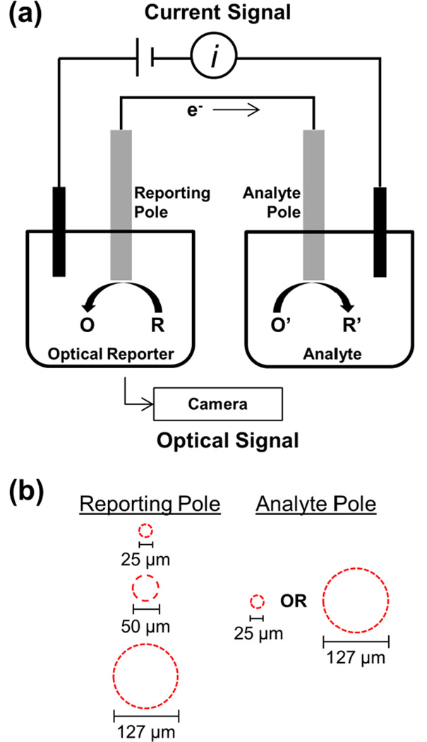
Figure 1 outlines our basic experimental setup. We form a closed BPE by electrically connecting two Pt disk microelectrodes, as has been previously reported.20,27,28 One pole of the BPE is placed in an analyte solution, and the other pole is placed in the optical reporter solution. In this study, the optical reporter is the Ru(bpy)32+/TPrA ECL system. As this ECL process entails oxidation reactions, reduction must occur at the analyte pole. To maintain electroneutrality in the BPE, the rate of oxidation on the reporting pole must be the same as the rate of reduction on the analyte pole. This is the basis behind using ECL as a reporter of the faradaic current through the BPE, assuming the ECL emission intensity scales with electrochemical current. To drive the coupled reactions, a potential is applied across the solutions using two driving electrodes. As the only electrical path from the ECL solution to the analyte solution is the BPE, the current through the system is equivalent to the current through the BPE, enabling simple measurement of the BPE current. The reporting pole is positioned on an inverted microscope to enable easy monitoring of ECL emission using a CCD camera. By simultaneously measuring the current through the BPE and the ECL emission from the reporting pole, one can gain a fundamental understanding of the relationship between these two signals. In order to understand the effect of electrode sizes on these signals, we use a 25, 50, or 127 µm diameter Pt disk electrode as the analyte pole and a 25 or 127 µm diameter Pt disk electrode as the reporter pole (Figure 1b).
Figure 1.
Diagram of the experimental setup used. (a) Schematic of the closed BPE setup, which enables simultaneous measurement of the current through the BPE and light emission from the reporting pole. In this report, the optical reporter (R) is Ru(bpy)32+ and TPrA, which are co-oxidized at the reporting pole and emit light through a complex reaction cascade. (b) Outlines of the electroactive areas of the different disk microelectrodes used as the two poles to make closed BPEs of different size geometries.
In this report, we first demonstrate both the basic coupling behavior of ECL to the reduction of ferricyanide on a closed BPE with equivalent pole sizes and the relationship between the optical and electrical signals. We then show the quantitative detection of various concentrations of ferricyanide using a 25 µm reporting pole and show the large changes in optical signal brought about by different size analyte poles. Using a simple voltammetric study of the ECL reaction in a non-bipolar setup, we explain this size effect. Lastly, we show how one can use information gained from the non-bipolar study of the ECL reaction to predict the optical response of the BPE to various analyte concentrations. We use this accurately predict important trends in the calibrations curves for the BPE detection of ferricyanide using a 127 µm reporting pole and different size analyte poles.
Results and Discussion
Bipolar Coupling of ECL and Analyte
We first sought to demonstrate the basic principle of bipolar coupling of ECL to an analyte on a closed BPE. As shown in previous studies using closed BPEs, the behavior of the bipolar system can be readily understood by considering each of the poles individually.20,21 More specifically, the potential required to drive coupled reactions on a BPE is approximately the difference between the potential required to drive each of the individual reactions in a traditional two or three electrode configuration. Additionally, one of the poles will limit the total current through the BPE, and this limit can also be understood by considering each pole individually.
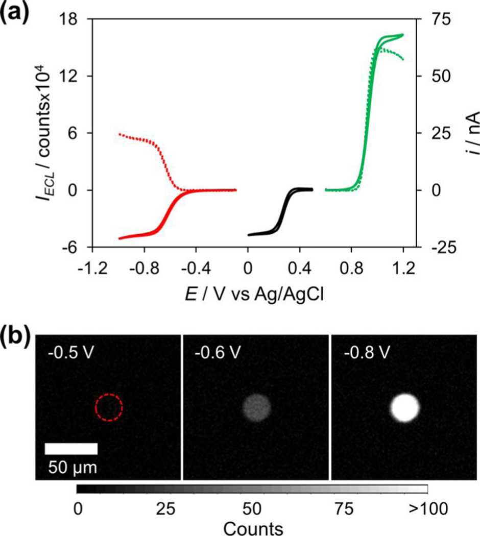
Figure 2 shows the results of an experiment in which the ECL and analyte reactions are considered both individually in traditional two electrode (non-bipolar) setups and coupled together in a closed BPE. The solid black trace shows the cyclic voltammogram of a 25 µm Pt electrode in 5 mM Fe(CN)63− with 1 M KCl as supporting electrolyte in a two-electrode setup. The potential was swept from 0.5 to 0 V. As seen, Fe(CN)63− reduction occurs with typical steady-state behavior and an onset potential of 0.33 V. The solid green trace shows the cyclic voltammogram of a 25 µm Pt electrode in ECL solution in a two-electrode setup during a potential sweep from 0.6 to 1.2 V. Again, typical steady-state behavior, although with a higher steady-state current, is observed for the oxidation of the ECL components (Ru(bpy)32+ and TPrA) with an onset potential of 0.85 V. The dashed green trace shows the simultaneously-recorded optical signal from this same electrode. As seen, the optical signal follows the electrical signal nearly exactly, exhibiting the same steady-state behavior and an onset potential of 0.87 V. The red traces show the simultaneously-recorded electrical (solid trace) and optical (dashed trace) signals for these individual reactions coupled together on a closed BPE. Both poles of the BPE were 25 µm Pt electrodes, with one (the analyte/cathodic pole) placed in 5 mM Fe(CN)63− and the other (the reporting/anodic pole) placed in ECL solution. In this setup, the reduction of Fe(CN)63− on the cathodic pole will be coupled to the oxidation of the ECL components on the anodic pole. The potential was applied to two Ag/AgCl driving electrodes and swept from −0.1 to −1 V. As can be seen, the electrical and optical signals follow one another very well, indicating that the ECL signal generated on the anode is a good reporter of the current through the BPE. Of note, there is a significant potential shift in the signal of the BPE as compared to the individual reactions, with the onset of the electrical and optical signals at −0.50 V and −0.57 V, respectively. As previously stated, this potential shift can be predicted by taking the difference in the onset potentials of the individual reactions. The predicted onsets of the electrical signal (0.33 V – 0.85 V = −0.52 V) and optical signal (0.33 V – 0.87 V = −0.54 V) agree very well with the observed bipolar onset potentials. The onset of the optical signal can be very clearly seen in Figure 2b, which shows images of the anodic pole at three potentials during the forward sweep of the BPE. As seen, an optical signal appears between −0.5 V and −0.6 V, and grows until it reaches a steady-state at −0.8 V.
Figure 2.
Relationship between two-electrode and bipolar potentials, electrical, and optical signals. All electrodes used were 25 µm Pt. (a) Black line: CV for an electrode in a two-electrode setup in 5 mM Fe(CN)63−. Solid green line: CV for an electrode in a two-electrode setup in ECL solution. Dashed green line: simultaneously recorded optical signal from the same electrode during the same scan as shown with the solid green line. Red lines: simultaneously recorded electrical (solid) and optical (dashed) signals for a bipolar setup in which the cathode was placed in 5 mM Fe(CN)63− and the anode was placed in ECL solution. (b) Images of the anode of the BPE at various potentials during the forward potential sweep. The actual position of the electrode is indicated by the dashed red ring.
Additionally, one can see that the steady-state current reached in the bipolar setup is the same as that reached in the two-electrode reduction of 5 mM Fe(CN)63−, indicating that the BPE signal is limited by the cathodic pole. Further discussion of limiting poles can be found in the supporting information, as well as in our previous reports on closed BPE systems.20,21 As expected, the optical signal also shows a similar decrease in magnitude from that obtained in a two-electrode setup. This is because the current through the BPE is lower due to the limitation from the cathodic pole, meaning that the rate of oxidation of the ECL components is slower and hence less light is emitted. Because ECL intensity is correlated to the reaction rate of the ECL components, which is in turn determined by the current through the BPE, the ECL intensity should correlate to the concentration of the analyte at the cathodic pole as long as the cathodic pole is limiting. This is the basis of using ECL as a reporter in a BPE sensing experiment.
Quantitative Detection and Influence of Anode Size
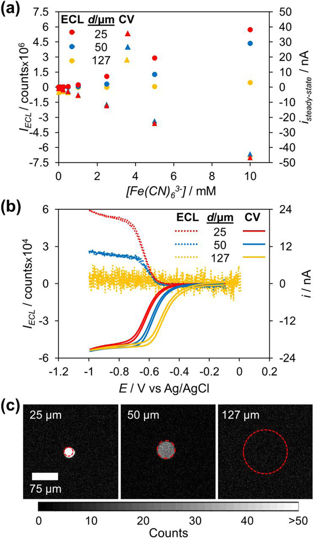
With an understanding of how ECL oxidation couples to analyte reduction, and in particular how information from the individual reactions can inform on the behavior of the coupled reactions, we moved on to study the quantitative detection of analyte on a BPE using ECL as a reporting mechanism. We studied both the electrical and optical response of a closed BPE to Fe(CN)63− concentrations ranging from 10 to 0.01 mM. In this experiment, a 25 µm Pt electrode was used as the cathodic pole and placed in Fe(CN)63− solution. To see what effect the size of the anode had on the signal, we used a 25, 50, or 127 µm Pt electrode as the anodic pole and placed it in ECL solution. We connected the two poles to form a closed BPE and applied a potential sweep from 0 to −1 V using two Ag/AgCl driving electrodes, during which we monitored the electrical and optical signals simultaneously. Figure 3a plots the steady-state current and steady-state ECL intensity (taken as the signal at −0.8 V during the forward sweep) for each anode size and Fe(CN)63−concentration. The full traces of these signals can be found in the supporting information.
Figure 3.
Results of a quantitative bipolar detection experiment. (a) Plot of the steady-state ECL intensity (circles) and steady-state current (triangles) for different Fe(CN)63− concentrations using three different anode sizes. An EM gain of 50 was used to collect the optical data. (b) ECL intensity (dashed lines) and current (solid lines) during potential sweeps for the detection of 5 mM Fe(CN)63−. No EM gain was used to collect the optical data. (c) Images of each anode at steady-state (−0.8 V forward sweep) during the detection experiment shown in (b). The actual electrode positions are outlined in red.
As expected, the steady-state current shows a linear dependence on Fe(CN)63− concentration that is independent of the size of the anodic pole, indicating that the cathodic pole is limiting in all cases. The ECL signal also has a linear dependence on Fe(CN)63− concentration as expected. However, quite unexpectedly, there is a striking change in the ECL intensity as the size of the anodic pole changes, with the ECL intensity significantly decreasing with increasing anode size for a given analyte concentration. With the basis of using ECL as a reporting mechanism being that it is an accurate reporter of the current, this data brought up a large discrepancy: How can the magnitude of the current through the BPE be independent of anode size yet the magnitude of the ECL intensity be strongly dependent on anode size?
This discrepancy is clearly seen in Figure 3b, which displays the current and ECL traces for the three different size anodes during potential sweeps using a Fe(CN)63− concentration of 5 mM at the cathodic pole.29 The steady-state ECL intensity decreases by more than a factor of 2 when the anode is changed from a 25 µm diameter disk to a 50 µm diameter disk. With a 127 µm diameter disk anode, there is no detectable ECL signal. These differences in intensity are very strikingly seen in the images of the anode at steady-state (Figure 3c). Images of the anodes at different cathodic concentrations of Fe(CN)63− can be found in the supporting information. Notably, the noise in the ECL signal increases dramatically as the anode size increases. As there is no inherent background light emission in ECL, this noise is due to the camera, and is the result of integrating over a larger number of pixels as the anode size increases (~ 25 times more pixels for the 127 µm anode vs. the 25 µm anode). However, this increase in noise cannot be responsible for a decrease in mean signal intensity. This consideration of camera noise does bring up an important point, however. If the same ECL intensity is observed on two different sized electrodes, the signal to noise ratio will be more favorable on the smaller electrode, as the same signal will be recorded on fewer pixels of the camera, resulting in less noise.30 This point is clearly demonstrated in the supporting information
The current traces in Figure 3b provide the first clue into solving our discrepancy. While the three anode sizes produce the same steady-state current, there is a marked potential shift between the different anode sizes, with the onset of current shifting from −0.50 V to −0.44 V to −0.34 V with anode sizes of 25, 50, and 127 µm, respectively. Despite this shift in the onset of current, the onset of ECL remains constant at −0.57 V for the 25 µm and 50 µm anodes. This is clearly showing that as the anode size increases, an increasing fraction of the current through the BPE is resulting in no light emission. To further explore this interesting result and explain our discrepancy, we chose to carefully study the ECL reaction in a non-bipolar, two-electrode setup.
Predicting Bipolar Behavior and Calibration Curves
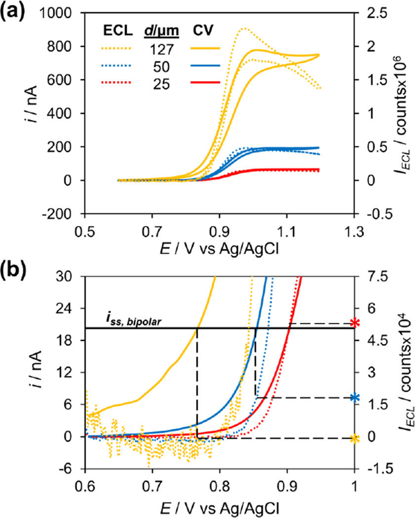
We did a simple two-electrode potential sweep experiment, using as working electrodes the same electrodes that served as anodes in our bipolar experiment (25, 50, or 127 µm diameter Pt disk microelectrodes). The potential was swept from 0.6 to 1.2 V to oxidize the ECL components while simultaneously recording the electrical and optical signals. Figure 4 presents the results of this experiment. As seen in Figure 4a, the ECL traces follow the current traces very closely. As expected, a larger electrode results in an increased current, which in turn results in a larger ECL signal due to a higher oxidation rate of the ECL components. However, notice that at the onset of the reactions, the current and ECL signal do not follow one another exactly. Figure 4b shows a zoom-in of the plot in 4a. The differences between the onset of current (solid lines) and the onset of ECL (dashed lines) become especially apparent here, with the difference growing as the electrode size increases. It has been previously shown that TPrA undergoes oxidation on Pt at a potential closer to 0 V than Ru(bpy)32+, explaining why there is current without ECL, as both species must be oxidized for light emission to occur.23,31,32 Due to an increased surface area where oxidation may occur, a larger electrode enables the same current to pass at a lower potential. Very interestingly, the Crooks group found this same phenomenon to be the cause limiting the ECL reporting signal at low faradaic currents on open BPEs5 and showed that decreasing the anode size relative to the cathode could boost the ECL signal.2 Our result apparently confirms this same phenomenon in closed BPEs.
Figure 4.
Results of a two-electrode potential sweep experiment with different size electrodes placed in ECL solution. The potential was swept from 0.6 to 1.2 V at 20 mV/s and the ECL signal (dashed lines) and current (solid lines) were simultaneously recorded. (b) is a zoom-in of (a), with the ECL intensities at the potential at which each electrode reaches the steady-state current produced by 5 mM Fe(CN)63− in the bipolar detection experiment in Figure 3b marked with asterisks.
We realized that this was the key to explaining the observed discrepancy between current and ECL signals in a bipolar setup. The solid black line in Figure 4b marks the steady-state current obtained for the bipolar detection of 5 mM Fe(CN)63− (experiment shown in Figure 3b). The dashed black lines mark the potential where that steady-state current is reached for each electrode in the two-electrode setup and extrapolate to the ECL curve to mark the ECL intensity achieved at that potential. This shows that a 127 µm electrode can reach the bipolar steady-state current before the onset of ECL, a 50 µm electrode reaches the steady-state current just after the onset of ECL, and a 25 µm electrode reaches the steady-state current well after the onset of ECL. One immediately notices that these ECL intensities (marked by the asterisks) match nearly exactly with the steady-state intensities observed for the bipolar detection of 5 mM Fe(CN)63− (shown in Figure 3b), showing how the ECL intensity can be dependent on anode size while the current remains independent of anode size in a closed BPE. As the anode size increases, the magnitude of “non-light-emitting current” also increases, resulting in less light emission.
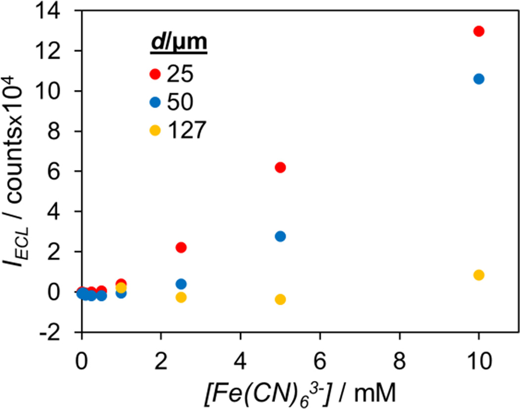
To see if the information from a two-electrode experiment as in Figure 4 could accurately predict the bipolar response of a range of analyte concentrations, we made calibration curves based on the data in Figure 4 and compared them to the curves obtained in an actual bipolar experiment as shown in Figure 3a. To make the predicted calibration curves, for each electrode size we found the potential where the steady-state current for a given Fe(CN)63− concentration was reached and marked the ECL intensity at that potential. Those ECL intensities were then plotted vs. Fe(CN)63− concentration, and the results are shown in Figure 5. As can be seen, this predicted calibration plot follows the calibration plot obtained in an actual bipolar experiment remarkably well. The supporting information contains a side-by-side view of the plots for easier comparison.
Figure 5.
Predicted calibration plot for the bipolar detection of Fe(CN)63− using different sized anodes and a 25 µm cathode.
Importantly, note that the predicted plot is based on data from a simple non-bipolar, two-electrode setup, but can be used to accurately predict important trends seen in the actual bipolar detection data. For example, the predicted calibration plot shows the linear region for the 25 µm anode to extend from 1–10 mM, the linear region for the 50 µm electrode to extend from 2.5–10 mM, and the 127 µm anode to only show a signal at 10 mM. These same trends are seen in the bipolar detection data. Additionally, the relative intensities for the three different size anodes at a given Fe(CN)63− concentration are accurately predicted. As can be seen, the information gained from studying the ECL reaction in a two-electrode setup is not only useful in understanding the bipolar response, but can be used to accurately predict a calibration plot for detecting an analyte in a bipolar detection experiment. This is a rather interesting point, as the predicted calibration plot can be built from one simple potential sweep experiment and with the only knowledge of the analyte needed the steady-state current it will produce at a given concentration.33
Applying Predicted Calibration Curves to Bipolar Detection
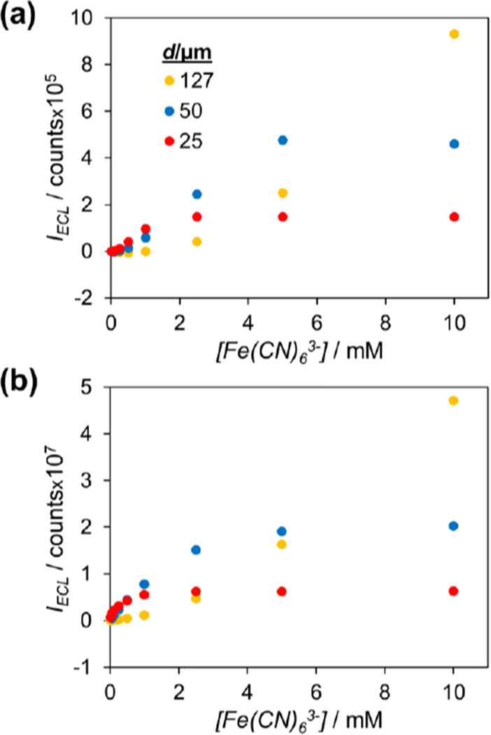
It is apparent from the discussion in the previous section that in order to increase the ECL signal from a given analyte concentration, the current through the BPE should be maximized. One way of doing this is to increase the size of the analyte pole (in this case the cathodic pole) of the BPE relative to the reporting pole. In fact, using the two-electrode data shown in Figure 4, we can predict the calibration plots for bipolar detection using a larger cathode. As an example, we made a calibration plot for Fe(CN)63− detection on a BPE with a 127 µm cathodic pole and either a 25, 50, or 127 µm anodic pole. To do this, we first calculated the steady-state current that each Fe(CN)63− concentration should give on a 127 µm electrode. Then, using the data shown in Figure 4, for each anode size we found the potential where the steady-state current of a given Fe(CN)63− concentration was reached and marked the ECL intensity at that potential. These ECL intensities were plotted vs. Fe(CN)63− concentration to complete the calibration plot. This predicted plot is shown in Figure 6a.
Figure 6.
Predicted (a) and experimental (b) calibration plots for the bipolar detection of Fe(CN)63− using different sized anodes and a 127 µm cathode.
Some very interesting trends are immediately seen in this plot. First, as compared to the plot in Figure 5 (which is based on a 25 µm cathode), the ECL signal is roughly an order of magnitude greater. This confirms that a larger cathode, and hence a larger current through the BPE, produces a larger ECL signal. More interestingly, the relative intensities between the anode sizes show a much different trend than in Figure 5. A 25 µm anode only shows sensitivity to Fe(CN)63− concentrations below 2.5 mM, while a 50 µm anode only shows sensitivity to concentrations below 5 mM. This is because at these concentrations and above, the ECL reaction at the anodic pole has reached its mass transfer-limited maximum, meaning the current through the BPE is limited by the anodic pole. Therefore, the steady-state current through the BPE, and hence, the steady-state ECL intensity, remain constant regardless of Fe(CN)63− concentration. The 127 µm anode shows no such limitation, as the theoretical maximum steady-state current at the anode is still greater than the current demand at the cathode. The third significant difference is that there is a significant shift in the linear region of the calibration curves. The 127 µm anode shows a linear response from 2.5–10 mM, the 50 µm anode shows a linear response from 0.5–5 mM, and the 25 µm anode shows a linear response from 0.1–1 mM.
Overall, the plot in Figure 6a predicts a very marked difference between using a 127 µm cathode and a 25 µm cathode for bipolar detection. For example, when using a 127 µm cathode, a 25 µm anode should show a linear range an order of magnitude lower in analyte concentration than if using a 25 µm cathode but should show no sensitivity to analyte concentrations over 2.5 mM. To verify that the predicted calibration plot shows the correct trends, we did the same bipolar detection experiment outlined in Figure 3, but used a 127 µm cathode rather than a 25 µm cathode. The results of this experiment are plotted in Figure 6b. As can be seen, the overall trends predicted in 6a are accurate. The linear range of the curves shift to lower concentrations for all three anode sizes, and the 25 and 50 µm anodes show limited to no sensitivity at higher Fe(CN)63− concentrations. We note that there are some deviations in the predicted vs. experimental curves, such as the experimental curves showing better sensitivity at lower analyte concentrations than predicted. We are investigating why this is but believe that oxygen reduction on the cathode may play a role in this. However, the overall trends in the calibration curve are very accurately predicted, which is the point we wish to emphasize.
Conclusions
The fundamental behavior of ECL coupling to analyte redox reaction on a closed bipolar microelectrode has been described for the oxidative Ru(bpy)32+/TPrA ECL system using a Pt BPE. We explicitly demonstrated the correlation between current through the BPE and ECL intensity at the reporting pole of the BPE, showing how these two signals change with changing analyte concentrations. Importantly, we also demonstrated the effect that changing the size-geometry of the BPE poles has on the optical signal and explained the origin of this size-effect. We found that changing the size-geometry of the BPE can significantly alter its sensing performance and show how one can take advantage of this to tune the BPE to different analyte concentration ranges. A smaller reporting pole relative to analyte pole showed a lower linear concentration detection range as well as better signal to noise ratio. Using data obtained from simple non-bipolar experiments, we demonstrated how calibration curves for BPE sensing experiments can be accurately predicted. We believe this report will be useful and provide valuable insight to those designing sensing systems based on closed BPEs, both in a single-electrode, and more excitingly, in an array-based format.
Experimental Section
Chemicals
Potassium ferricyanide (K3Fe(CN)6), tripropylamine (TPrA), and tris(2,2’-bipyridyl)dichlororuthenium(II) hexahydrate (Ru(bpy)3Cl2·6H2O) were purchased from Sigma-Aldrich (St. Louis, Missouri). Potassium chloride was purchased from Fisher Scientific (Fair Lawn, New Jersey). All chemicals were used as received. Deionized water (>18 MΩ·cm) obtained from a Barnstead Nanopure water purification system was used for all aqueous solutions. All solutions of Fe(CN)63− were prepared in 1 M KCl. The ECL solution, which consisted of 5 mM Ru(bpy)32+ and 25 mM TPrA, was prepared in 0.1 M pH 7.0 phosphate buffer.
Electrochemical Measurements
All voltammetry experiments were carried out using a Chem-Clamp potentiostat (Dagan Corporation) interfaced to a PC through a PCI-6251 data acquisition board (National Instruments) using a BNC-2090 breakout box (National Instruments). An in-house LabView 10.0 (National Instruments) program was used for voltage function generation and acquisition of the current-voltage data. This program receives an external trigger from a camera, enabling the synchronized recording of electrochemical and optical signals. In a non-bipolar/two-electrode setup, a traditional two-electrode system was used, with the potential being applied between the working electrode and an Ag/AgCl reference electrode. In a closed bipolar setup, the potential was applied across the BPE using two Ag/AgCl reference electrodes. Closed BPEs were formed by electrically connected two working electrodes in separate solutions. The working electrodes used were inlaid-disk Pt microelectrodes with a diameter of 25, 50, or 127 µm. These electrodes were fabricated by sealing a Pt microwire (Alfa-Aesar) in a borosilicate capillary (Sutter Instrument Co.) and making connection to the Pt with tungsten wire and Ag paint (Dupont) through the back end of the capillary. All reported potentials are vs. Ag/AgCl (3 M KCl), and all cyclic voltammetry experiments were done at a scan rate of 20 mV/s. Onset potentials are calculated as the potential at which the current reaches 10% of its steady-state value. All reported electrochemical measurements are the average of three trials.
Optical Measurements
An Olympus IX70 inverted microscope and an Andor iXon EMCCD camera cooled to −80 °C were used to image the ECL signal. All imaging was done through a 10× 0.30 NA objective (Olympus UPlanFl) using an additional 1.5× magnification on the microscope. Andor SOLIS software was used to record and process all images. Images were recorded using an exposure time of 0.1 s, giving a frame rate of 9.9522 Hz. A preamplifier gain of 5.1 was used. The ECL intensity was determined by integrating the counts from the area over each electrode. Reported images and intensities are background-corrected, typically using the first frame in a series as the background. For imaging, each electrode was placed 500 µm above a coverslip using a Sutter MP-285 motorized micromanipulator (Sutter Instrument Co.). Onset potentials from the optical signal are reported as the potential at which the optical signal reaches 10% of its steady-state intensity. As with the electrochemical measurements, all reported optical measurements are the average of three trials.
Supplementary Material
Acknowledgments
The authors gratefully acknowledge financial support provided by the National Science Foundation (CHE 1212805) and the National Institutes of Health (GM101133). S.M.O. was supported by the American Chemical Society Division of Analytical Chemistry Graduate Fellowship sponsored by Eastman Chemical.
References
- 1.Arora A, Eijkel JCT, Morf WE, Manz A. Anal. Chem. 2001;73:3282–3288. doi: 10.1021/ac0100300. [DOI] [PubMed] [Google Scholar]
- 2.Zhan W, Alvarez J, Crooks RM. J. Am. Chem. Soc. 2002;124:13265–13270. doi: 10.1021/ja020907s. [DOI] [PubMed] [Google Scholar]
- 3.Chow K-F, Mavré F, Crooks RM. J. Am. Chem. Soc. 2008;130:7544–7545. doi: 10.1021/ja802013q. [DOI] [PubMed] [Google Scholar]
- 4.Chow K-F, Mavré F, Crooks JA, Chang B-Y, Crooks RM. J. Am. Chem. Soc. 2009;131:8364–8365. doi: 10.1021/ja902683f. [DOI] [PubMed] [Google Scholar]
- 5.Mavré F, Chow K-F, Sheridan E, Chang B-Y, Crooks JA, Crooks RM. Anal. Chem. 2009;81:6218–6225. [Google Scholar]
- 6.Fosdick SE, Crooks JA, Chang B-Y, Crooks RM. J. Am. Chem. Soc. 2010;132:9226–9227. doi: 10.1021/ja103667y. [DOI] [PubMed] [Google Scholar]
- 7.Chang B-Y, Mavré F, Chow K-F, Crooks JA, Crooks RM. Anal. Chem. 2010;82:5317–5322. doi: 10.1021/ac100846v. [DOI] [PubMed] [Google Scholar]
- 8.Wu M-S, Xu B-Y, Shi H-W, Xu J-J, Chen H-Y. Lab Chip. 2011;11:2720–2724. doi: 10.1039/c1lc20143c. [DOI] [PubMed] [Google Scholar]
- 9.Wu M-S, Qian G-S, Xu J-J, Chen H-Y. Anal. Chem. 2012;84:5407–5414. doi: 10.1021/ac3009912. [DOI] [PubMed] [Google Scholar]
- 10.Chang B-Y, Chow K-F, Crooks JA, Mavré F, Crooks RM. Analyst. 2012;137:2827–2833. doi: 10.1039/c2an35382b. [DOI] [PubMed] [Google Scholar]
- 11.Wu M-S, Yuan D-J, Xu J-J, Chen H-Y. Chem. Sci. 2013;4:1182–1188. [Google Scholar]
- 12.Zhang X, Chen C, Li J, Zhang L, Wang E. Anal. Chem. 2013;85:5335–5339. doi: 10.1021/ac400805f. [DOI] [PubMed] [Google Scholar]
- 13.Lin X, Zheng L, Gao G, Chi Y, Chen G. Anal. Chem. 2012;84:7700–7707. doi: 10.1021/ac300875x. [DOI] [PubMed] [Google Scholar]
- 14.Zhang X, Li J, Jia X, Li D, Wang E. Anal. Chem. 2014;86:5595–5599. doi: 10.1021/ac501246k. [DOI] [PubMed] [Google Scholar]
- 15.Wu S, Zhou Z, Xu L, Su B, Fang Q. Biosens. Bioelectron. 2014;53:148–153. doi: 10.1016/j.bios.2013.09.042. [DOI] [PubMed] [Google Scholar]
- 16.Zhang J-D, Yu T, Li J-Y, Xu J-J, Chen H-Y. Electrochem. Commun. 2014;49:75–78. [Google Scholar]
- 17.Wu M-S, Liu Z, Shi H-W, Chen H-Y, Xu J-J. Anal. Chem. 2015;87:530–537. doi: 10.1021/ac502989f. [DOI] [PubMed] [Google Scholar]
- 18.Eßmann V, Jambrec D, Kuhn A, Schuhmann W. Electrochem. Commun. 2015;50:77–80. [Google Scholar]
- 19.Fosdick SE, Knust KN, Scida K, Crooks RM. Angew. Chem. Int. Ed. 2013;52:2–21. doi: 10.1002/anie.201300947. [DOI] [PubMed] [Google Scholar]
- 20.Guerrette JP, Oja SM, Zhang B. Anal. Chem. 2012;84:1609–1616. doi: 10.1021/ac2028672. [DOI] [PubMed] [Google Scholar]
- 21.Cox JT, Guerrette JP, Zhang B. Anal. Chem. 2012;84:8797–8804. doi: 10.1021/ac302219p. [DOI] [PMC free article] [PubMed] [Google Scholar]
- 22.Noffsinger JB, Danielson ND. Anal. Chem. 1987;59:865–868. [Google Scholar]
- 23.Zu Y, Bard AJ. Anal. Chem. 2000;72:3223–3232. doi: 10.1021/ac000199y. [DOI] [PubMed] [Google Scholar]
- 24.Guerrette JP, Percival SJ, Zhang B. J. Am. Chem. Soc. 2013;135:855–861. doi: 10.1021/ja310401b. [DOI] [PubMed] [Google Scholar]
- 25.Oja SM, Guerrette JP, David MR, Zhang B. Anal. Chem. 2014;86:6040–6048. doi: 10.1021/ac501194j. [DOI] [PMC free article] [PubMed] [Google Scholar]
- 26.Oja SM, Zhang B. Anal. Chem. 2014;86:12299–12307. doi: 10.1021/ac5035715. [DOI] [PubMed] [Google Scholar]
- 27.Hotta H, Akagi N, Sugihara T, Ichikawa S, Osakai T. Electrochem. Commun. 2002;4:472–477. [Google Scholar]
- 28.Plana D, Jones FGE, Dryfe RAW. J. Electroanal. Chem. 2010;646:107–113. [Google Scholar]
- 29.The data shown in (b) is from a different trial than the data shown in (a). For the data shown in (a), an electron multiplier (EM) gain of 50 was used, while no EM gain was used for the data displayed in (b). This is why the ECL intensities are ~50 times greater in (a) than in (b).
- 30.We emphasize that this only holds true for a pixel-based detector, such as a CCD camera (as opposed to a detector such as a photomultiplier tube).
- 31.Kanoufi F, Zu Y, Bard AJ. J. Phys. Chem B. 2001;105:210–216. [Google Scholar]
- 32.Miao W, Choi J-P, Bard AJ. J. Am. Chem. Soc. 2002;124:14478–14485. doi: 10.1021/ja027532v. [DOI] [PubMed] [Google Scholar]
- 33.The steady-state current for a given analyte concentration can be easily calculated for a known electrode geometry. See: Bard AJ, Faulkner LR. Electrochemical Methods. 2nd. chapter 5. New York: John Wiley & Sons; 2001. For the inlaid-disk microelectrodes used in this report, the steady-state current iss, will be given by the equation: iss = 4nFC*Dr, where n is the number of electrons transferred per analyte molecule reacted, F is the Faraday constant, C* is the bulk concentration of the analyte, D is the diffusion coefficient of the analyte, and r is the radius of the electrode.
Associated Data
This section collects any data citations, data availability statements, or supplementary materials included in this article.


