Abstract
Ceramic restorations, whether monolithic (single layer) or porcelain veneered, often chip and fracture from repeated occlusal loading. Occlusion involves the opposing tooth sliding along the cuspal incline surface with an applied biting force (off-axis loading). We hypothesize that off-axis contact–load–slide–liftoff fatigue as compared to normal axial fatigue loading produces different fracture modes and fatigue lifespan of layered ceramics. Monolithic glass plates were epoxy bonded to polycarbonate substrates as a transparent model for an all-ceramic crown on dentin. Off-axis and axial (control) cyclic loading was applied through a hard sphere in water with a mouth-motion machine. The off-axis loading is more deleterious for contact-induced occlusal surface fracture, but less harmful for flexure-induced cementation surface fracture of brittle layers than the axial loading. This is because of the tangential load component associated with the off-axis loading. Clinical relevance is discussed.
Keywords: off-axis loading, fatigue, cementation radial fracture, occlusal partial cone fracture, layered ceramic structures
INTRODUCTION
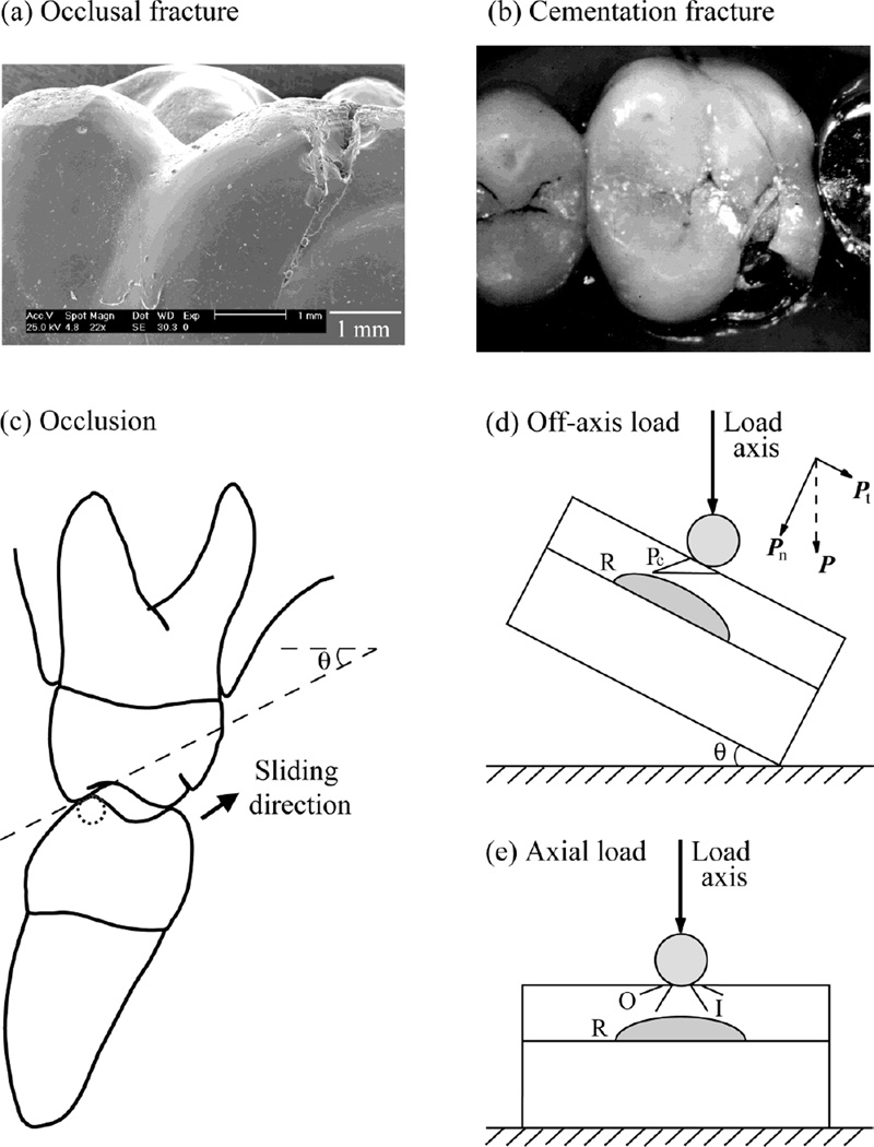
Molar crowns are subjected to high chewing stresses, and thus are vulnerable to fracture. Two clinical failure types are reported: occlusal surface fracture originated from the contact site [Fig. 1(a)] (Sailer et al., 2006; Scherrer et al., 2001); and bulk fracture initiated from the cementation surface directly beneath the contact [Fig. 1(b)] (Kelly et al., 1995; Scherrer et al., 2001). Posterior tooth contact in a chewing cycle begins with an eccentric contact of the mandibular buccal cusps with the inner inclines of the maxillary buccal cusps, followed by a sliding movement through centric occlusion, and then lifting off [Fig. 1(c)]. The average length of the sliding path of a first molar is ~0.5 mm (DeLong and Douglas, 1983). A typical inner incline of the maxillary buccal cusps has a radius of ~10 cm and a inclination angle of ~30° (DeLong and Douglas, 1983). Since the sliding path is much shorter than the radius of the cusps, the sliding movement can be visualized as a straight-line motion of a spherical indenter on the surface of a flat brittle layer (crown) supported by a complaint substrate (tooth dentin) with an inclination angle θ = 30° [Fig. 1(d)].
Fig. 1.
Fracture of porcelain veneered dental crowns: (a) occlusal failure of a Cerestore upper right first molar crown (pressed shrink-free 70% Al2O3 and 22% MgAl2O4 spinel framework veneered with aluminous porcelain) 19 years of intraoral service (Scherrer et al., 2001), and (b) bulk fracture from the cementation surface of an In-Ceram upper left first molar crown (glass infiltrated 95% Al2O3 framework veneered with aluminous porcelain) 3.5 years in service (Scherrer et al., 2001). The aluminous porcelain veneer comprised a combination of feldspath and alumina so that it’s coefficient of thermal expansion matched that of the respective cores. The occlusal surfaces of these crowns were glazed after adjusting the occlusion intraorally. The internal surfaces of the crowns were untreated prior to cementation using glass-ionomer cements. (c) Schematic of tooth eccentric occlusal position of right side first molar. Arrow indicates direction of sliding as teeth move to centric occlusion. Cuspal inclination slope and angulation (θ) are shown. (d) Experimental arrangement for indentation of brittle layer on compliant substrate with an inclination angle θ = 30° (Off-axis loading). Showing two crack modes: occlusal surface partial cone cracks (Pc), and cementation surface radial cracks (R). Note the superposed tangential force component. (e) Experimental control of axial loading (θ = 0°) of brittle layer on compliant substrate. Showing three crack modes: occlusal surface outer cone cracks (O) and inner cone cracks (I), and cementation surface radial cracks (R).
Previous studies have reported that sliding contact generates a series of partial cone cracks on the occlusal surface, which propagate deeper and faster than the outer and inner cone cracks associated with axial fatigue loading (Kim et al., 2007; Lawn et al., 1984; Zhang et al., 2008). However, effects of loading an inclined surface, i.e. off-axis loading [Fig. 1(d)], on damage evolution of flexure-induced cementation surface radial cracks in addition to sliding induced occlusal surface partial cone cracks have not been investigated. Since there are different types of damage modes, competitions may exist. This study sought to address these issues by employing mouth-motion like fatigue with off-axis loading configuration (θ = 30°) [Fig. 1(d)] on ceramic layers on compliant substrates with axial loading control (θ = 0°) [Fig. 1(e)]. Soda-lime glass plates bonded to polycarbonate substrates are used as a model system because glass is transparent, permitting in-situ observation of crack evolution. In addition, on going research from our laboratory find the same damage modes in Hertzian contact fatigue of glass-ceramic layers silanated and cemented to dental composites (Z100, 3M ESPE) (Rekow et al., 2007; Silva et al., 2008) as in glass layers on polycarbonate substrates. As we gain a solid understanding of these flat-layer systems, we are gradually introducing complexities in specimen geometries, approaching the actual tooth/crown function.
MATERIALS & METHODS
Material systems
Soda-lime glass plates (25×25×1 mm, Daigger, Wheeling, IL) were polished on their side surfaces for in-situ viewing during testing. The top surfaces of the glass plates were abraded with 600-grit SiC to generate an adequate flaws density for cone crack initiation. The glass plates were randomly divided into two groups. 1. The bottom surfaces of the plates were etched with 9.5% hydrofluoric acid for 5 min to remove surface flaws and to avoid flexure-induced bulk fracture from the cementation interface. So the top surface damage maps can be constructed. 2. The bottom surfaces were grit blasted with airborne alumina particles (mean particle size 50 µm with 276 KPa compressed air pressure for 5 s at a stand-off distance 10 mm) to introduce flaws for radial crack initiation (Zhang et al., 2004; Zhang et al., 2006). Plates were then joined to the polycarbonate substrates (12.5 mm thick, AlN Plastics, Norfolk, VA) with a thin layer (~10 – 20 µm) of epoxy adhesive, which was allowed to cure for 48 hrs.
Fatigue tests
To facilitate direct comparison of damage response of brittle layers on compliant substrates under axial (θ = 0°) and off-axis (θ = 30°) loading, Hertzian indentation fatigue tests were carried out on glass/polycarbonate bilayers with spherical tungsten carbide indenters of radius r = 1.5 mm in water using a mouth-motion simulator (Elf 3300, EnduraTEC Division of Bose, Minnetonka, MN). Each load cycle consisted of the indenter contacting the specimen, loading to a maximum, holding for 0.35 s, unloading, and lifting off. A loading and unloading rate of 1000 N/s was employed. For axial loading, specimen was mounted onto a horizontal block and the entire contact–load–hold–liftoff cycle was restricted to the vertical direction. For off-axis loading, specimen was mounted onto an inclined block [θ = 30°, Fig. 1(d)]. Load was applied in the vertical direction, but the loading consisted of contact–load–slide–liftoff sequence, i.e. the indenter contacting the specimen, loading to a maximum while sliding down the surface to create a wear facet ~0.5 mm in length, unloading, and lifting off from the specimen surface. The off-axis loading configuration resulted in superposed normal and tangential load components Pn = P cos θ and Pt = P sin θ, producing a coefficient of friction μ = Pt/Pn = tan θ = tan 30° = 0.58 [Fig. 1(d)]. Previous study showed that only the normal load Pn is responsible for the cementation surface radial fracture (Lee et al., 2001). Thus, the rationale used to choose maximum fatigue loads for the onset of radial cracks was that the normal load component Pn in off-axis loading was equivalent to the maximum load P in axial loading.
The current fatigue tests were designed to determine the number of cycles to failure nF for a range of prescribed maximum loads 50 – 510 N. This load range covered most of the load values recorded during mastication and swallowing (~5 – 364 N) (Kelly, 1999). Failure of brittle layers on compliant substrates was defined when one of the top, occlusal surface crack systems reached the ceramic/cement interface, or when large, cementation surface radial cracks (typically 5 – 10 mm in the lateral dimension) popped-in. The definition of failure by cementation surface radial cracking, unlike that for the occlusal surface damages, is its initiation. This is because (1) radial cracks initiate at a large size, typically 5 – 10 mm in the lateral dimension, which is in the same scale of a molar crown; and (2) radial cracks seldom merge to the flat specimen surface, rather extend sideways to the specimen edges, due to the development of a compressive stress zone in the vicinity of the occlusal contact area.
A minimum of three specimens were tested for each prescribed fatigue load and for each loading condition (axial or off-axis). All tests were recorded using a video camcorder (Canon XL1, Canon, Lake Success, NY) equipped with a microscope zoom system (Zhang et al., 2005b). Damage maps were constructed for glass/polycarbonate bilayers. An analysis of covariance (ANCOVA) was used to compare the number of cycles to failure as a function of loading condition (axial or off-axis) and prescribed maximum load. In all cases, cycles to failure and the maximum fatigue load were log10 transformed. No overlap of the 95% confidence bound between the experimental groups was considered as significant.
RESULTS
Crack morphology
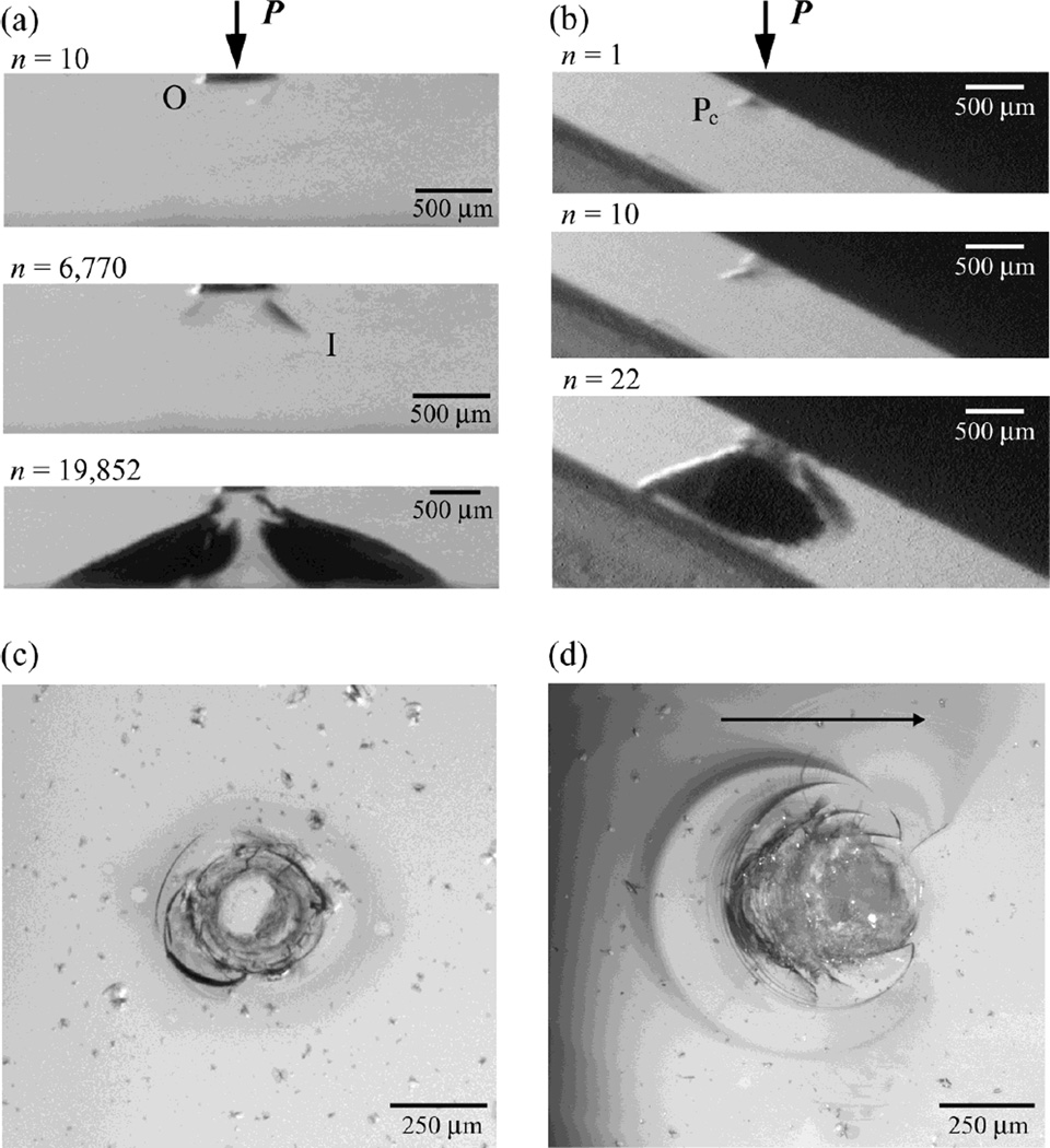
In bottom cementation surface etched glass plates on polycarbonate bilayers, cone cracks were the dominant mode of fracture but differed in evolution for axial and off-axis loading [Fig. 2(a) and (b)]. In axial fatigue loading at P = 120 N [Fig. 2(a)], side view video frames showed that outer cone initiated first and propagated downward and outward with a shallow angle α = 22 ± 5° in respect to the specimen surface. Inner cone cracks formed within the contact region from the occlusal surface and propagated downward at a relatively high rate and steep angle (55 ± 15°). In off-axis fatigue loading at P = 120 N [Figs. 2(b)], a series of partial cone cracks (distorted outer cones of axial loading) formed in the first contact–load–sliding–liftoff cycle. Side view images revealed trailing edges of the partial cones having an inclination angle α’ = 52 ± 10°, which was much steeper than for classical outer cones in axial loading (α = 22 ± 5°). Intrusion of water into the inner or partial cone cracks was evident, especially during the loading or sliding cycle, respectively. When inner or partial cones reached approximately halfway through the glass thickness, they began to experience the plate flexure induced tensile stresses and surged abruptly to the glass polycarbonate interface. The main difference between the off-axis and axial loading, for bottom surface etched specimens, was propagation of the partial cones to the glass polycarbonate interface rather than the inner cones in the latter.
Fig. 2.
Side view video sequence of cone cracks evolving in glass plate on polycarbonate bilayers with (a) axial and (b) off-axis loading following various numbers of cycle n. Post mortem occlusal view optical micrographs of glass/polycarbonate bilayers subjected to (c) axial and (d) off-axis loading for n = 19,852 and 22 cycles, respectively. Arrow in (d) indicates the sliding direction for the off-axis test. Indentation with tungsten carbide sphere of radius r = 1.5 mm, P = 120 N, in water. Note in (a) outer cone (O) forms first but inner cones (I) propagate to glass/polycarbonate interface. In (b) partial cones (Pc) penetrate through the glass layer. In (c) a set of complete concentric ring cracks centered at the indentation site, and in (d) a series of incomplete partial cones formed at the wake of a moving indenter.
Post mortem occlusal views of the respective side view specimens [Figs. 2(a) and (b)] following fatigue failure are included for comparison [Figs. 2(c) and (d)]. A set of complete concentric ring cracks centered at the indentation site formed in axial loading [P = 120 N, n = 19,852, Fig. 2(c)], while an elongated wear track consisting of a series of closely spaced incomplete ring cracks formed at the trailing edge of the sliding indenter in off-axis loading [P = 120 N, n = 22, Fig. 2(d)].
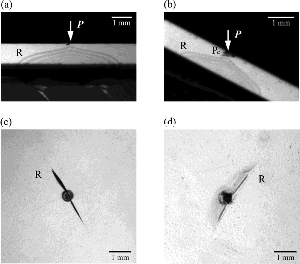
In bottom surface grit blasted glass plates on polycarbonate substrates, cementation radial cracks formed in addition to the above described occlusal surface cone cracks. Side and cementation surface views revealed the onset of radial cracking in glass/polycarbonate structures subjected to axial loading at P = 75 N after n = 514 cycles [Figs. 3(a)] and off-axis loading at P = 86 N (Pn = P cos 30° = 75 N) after n = 547 cycles [Figs. 3(b)]. These large radial cracks initiated from the cementation surface and propagated sideward and upward.
Fig. 3.
Side view video frames of cementation radial cracks (R) initiation in glass plate on polycarbonate bilayers with (a) axial and (b) off-axis loading following P = 75 N for n = 514 and P = 86 N for n = 547, respectively. Post mortem cementation view optical micrographs of respective glass/polycarbonate bilayers subjected to (c) axial loading at P = 75 N for n = 514 and (d) off-axis loading at P = 86 N for n = 547.
Damage maps
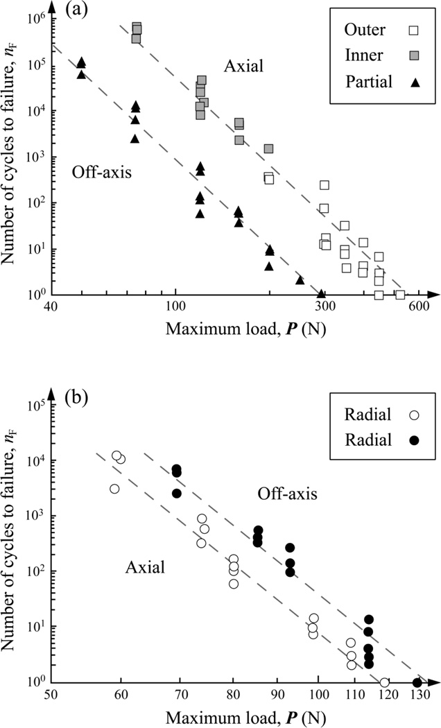
Damage maps (load-cycles-type of failure) are reported for top, occlusal surface damage [Fig. 4(a)] and bottom, cementation surface damage [Fig. 4(b)] in glass/polycarbonate system subjected to axial and off-axis fatigue loading. In the case of axial loading, failure was from outer cone cracks at high loads (unfilled symbols) and inner cone cracks at low loads (grey symbols). In the case of off-axis loading, failure was exclusively from partial cone cracks. Statistics analysis (ANCOVA) revealed that, for a given load P, off-axis loading resulted in significantly lower number of cycles [by over two orders of magnitude, Fig. 4(a)] to propagate contact-induced occlusal cone cracks to the glass/polycarbonate interface, but higher number of cycles [by a factor of five, Fig. 4(b)] to initiate flexure-induced cementation surface radial cracks compared to axial loading.
Fig. 4.
Plot of number of cycles nF to failure as a function of maximum load P in glass/polycarbonate bilayers for (a) occlusal surface cone fracture and (b) cementation surface radial fracture following axial and off-axis fatigue. In (a), the maximum fatigue loads P investigated were 75, 120, 160, 200, 300, 350, 400, 450, and 510 N for axial loading, and 50, 75, 120, 160, 200, 250, and 290 N for off-axis loading. In (b), the maximum fatigue loads P used are 60, 75, 80, 99, 109, and 119 N for axial loading and 69, 86, 93, 114, and 129 N for off-axis loading. Indentation with tungsten carbide sphere of radius r = 1.5 mm, in water. Failure occurs when occlusal cone cracks penetrate to glass/polycarbonate interface or cementation radial cracks pop-in at critical number of cycles nF.
DISCUSSION
This paper has investigated the influence of off-axis fatigue loading on crack modes and fatigue life of brittle layer structures using a hard sphere on glass/polycarbonate bilayers as a model system. Definitive experiments have been conducted using off-axis loading (with an inclination angle θ = 30°, analogous to tooth contact during mastication) and normal axial loading (θ = 0°). Our findings show that off-axis loading is highly deleterious for contact-induced occlusal surface cone fracture, reducing the fatigue lifespan of glass plate due to cone fracture by over two orders of magnitude compared to axial loading. Off-axis loading is, however, less harmful for flexure-induced radial fracture, increasing the fatigue lifespan owing to radial fracture by ~5 times relative to axial loading.
In off-axis loading, the specimen surface normal is tilted for an angle θ in respect to the loading axis, equivalent to loading a maxillary first molar on the buccal incline surface and sliding downward to the centric occlusal position. At a critical load, a cone crack forms with its orientation (the cone axis) in the direction of applied load P. When the inclination angle is larger than the cone angle, i.e. θ > α [for soda-lime glass, α ≈ 22° (Kocer and Collins, 1998)], a part of the virtual cone crack protrudes out of the surface, resulting in a partial cone configuration. Explicit equations A1, A4 and A5 (Appendix A) quantitatively predict that the penetration depth h’ and angle α’ of partial cone cracks for off-axis loading are greater than those for axial loading. The greater the inclination angle θ, the deeper the partial cone penetrates. In addition, once partial cones formed, they propagate at a faster rate than the outer or inner cones in axial loading. Previous studies show that outer cones only experience tensile stresses throughout the entire contact–load–liftoff cycle and thus, are driven predominantly by slow crack growth mechanism (Bhowmick et al., 2005; Zhang et al., 2005a). Inner cones and partial cones are subjected to both tensile and compressive stresses and hence, are driven by hydraulic pumping in addition to slow crack growth (Kim et al., 2007). However, partial cones experience an enhanced compressive stress at the full engulfment of the indenter and an intensified tensile stress at the trailing edge of the moving indenter, owing to the friction associated tangential load component (Appendix A). Inner cones only experience smaller tensile stresses and must undergo an incubation stage during which they are completely trapped in the Hertzian compression zone (Kim et al., 2007).
We now consider internal radial fracture, originating from the cementation interfaces. In off-axis loading, the applied load P can be resolved to the normal load Pn and a tangential load Pt. Only the normal load Pn = P cos θ is responsible for the initiation of cementation surface radial cracks. For θ = 30°, the normal load component Pn is ~87% of the applied load P. However, for a steeper inclination angle θ = 60°, the normal load component Pn is reduced to ~50% of the applied load P. Therefore, an inclined angle is beneficial for preventing the bulk radial fracture. The greater the inclination angle θ, the higher the load is required to initiate radial cracking (Eqs. B1 and B2, Appendix B).
The current study shows that the cuspal angulation θ has twofold effects on damage evolution in layered ceramic structure on compliant substrate. A large inclination angle facilitates cone fracture at the occlusal surface, but prevents radial fracture from the cementation surface. Cementation radial cracking could develop into bulk fracture, leading to catastrophic failure of ceramic restorations. Occlusal cone cracking may result in chipping of ceramic restorations or penetrate to the ceramic/cement interface (monolithic crowns) or veneer/core interface (veneered crowns). Although the incidence of occlusal cone cracks may not result in catastrophic failure of the ceramic restoratives as may cementation radial fractures, they may nevertheless provide pathways for external elements to the interior of the layer system. In the case of weak interfaces, cone cracks can promote interlayer delamination. Therefore, for design of the monolithic (single layer) ceramic crowns, a thick ceramic layer coupled with a large cuspal angulation is recommended to prevent bulk fracture from cementation radial cracking, so as to inhibit fatigue failure from occlusal cone fracture.
We acknowledge that dental crowns have complex geometries. Flat specimens have limitations in demonstrating other fracture modes such as margin fracture. Studies of single-cycle loading on curved structures have revealed margin fracture (Qasim et al., 2007), similar to those observed clinically (Qasim et al., 2005).
Acknowledgments
Thanks are due to Dr. Suzanne S. Scherrer for providing photos of clinically fractured crowns and Dr. Malvin Janal for statistic analysis. This work is supported by Grant Number 1R01 DE017925 (PI. Zhang) from NIDCR/NIH and the New York University Research Challenge Fund.
APPENDIX: CRACK CONFIGURATIONS UNDER OFF-AXIS LOADING
A. PARTIAL CONE
The far-field approximation solution for the penetration depth h of a virtual cone under a normal load P is given by (Lawn, 1993):
| (Eq. A1) |
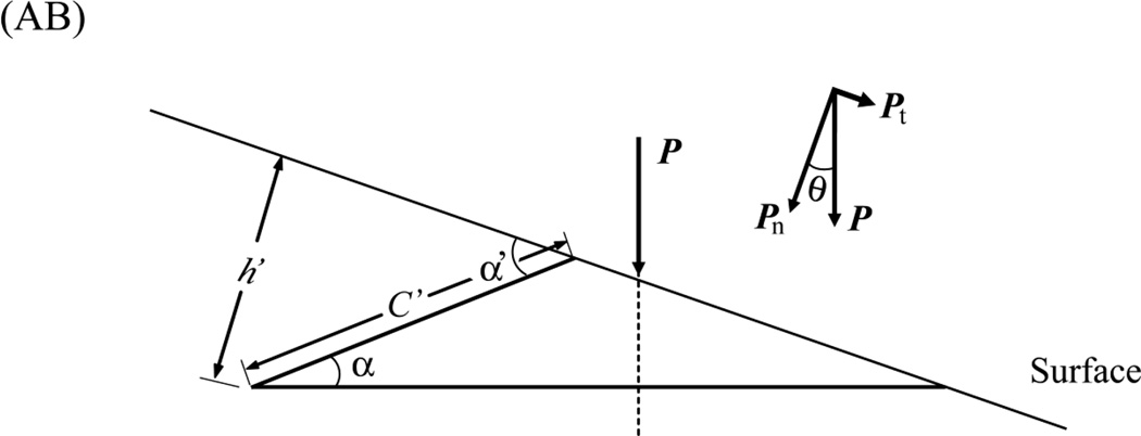
where Kc is the stress-intensity factor, χ is a crack geometry coefficient, and α the inclination angle of the cone in respect to the specimen surface (Fig. AA).
If the specimen normal is tilted an angle θ from the load axis (Fig. AB), the applied load P can be resolved into two vectorial components: a normal load Pn = P cos θ and a tangential force Pt = P sin θ (Fig. AB):
| (Eq. A2) |
Assuming the indenter slides at a constant velocity, we have:
| (Eq. A3) |
Combining equations (A1), (A2), (A3), and h’ = C’ sin α’, the penetration depth, h’, of a partial cone at its steepest side for inclined loading is given by:
| (Eq. A4) |
and
| (Eq. A5) |
B. BOTTOM RADIAL
In axial loading, the critical load P for radial cracking initiation is the determined by the thickness d and strength S of the brittle layer (Lawn et al., 2002):
| (Eq. B1) |
Where B = 1.35 is a dimensionless constant, Ec and Es are moduli of the ceramic coating and compliant substrate respectively.
In off-axis loading, the applied load P can be resolved to the normal load Pn and a tangential load Pt [Fig. 1(d)]. Only the normal load component Pn = P cos θ is responsible for the bottom radial fracture.
| (Eq. B2) |
(AA) Axial loading
(AB) Off-axis loading
Footnotes
Presented in part before the 85th General Session & Exhibition of the IADR March 2007, New Orleans, Louisiana
REFERENCES
- Bhowmick S, Zhang Y, Lawn BR. Competing fracture modes in brittle materials subject to concentrated cyclic loading in liquid environments: Bilayer structures. Journal of Materials Research. 2005;20(10):2792–2800. [Google Scholar]
- DeLong R, Douglas WH. Development of an artificial oral environment for the testing of dental restoratives: bi-axial force and movement control. J Dent Res. 1983;62(1):32–36. doi: 10.1177/00220345830620010801. [DOI] [PubMed] [Google Scholar]
- Kelly JR, Tesk JA, Sorensen JA. Failure of all-ceramic fixed partial dentures in vitro and in vivo: analysis and modeling. J Dent Res. 1995;74(6):1253–1258. doi: 10.1177/00220345950740060301. [DOI] [PubMed] [Google Scholar]
- Kelly JR. Clinically Relevant Approach to Failure Testing of All-Ceramic Restorations. Journal of Prosthetic Dentistry. 1999;81(6):652–661. doi: 10.1016/s0022-3913(99)70103-4. [DOI] [PubMed] [Google Scholar]
- Kim JW, Kim JH, Thompson VP, Zhang Y. Sliding contact fatigue damage in layered ceramic structures. J Dent Res. 2007;86(11):1046–1050. doi: 10.1177/154405910708601105. [DOI] [PMC free article] [PubMed] [Google Scholar]
- Kocer C, Collins RE. The Angle of Hertzian Cone Cracks. Journal of the American Ceramic Society. 1998;81(7):1736–1742. [Google Scholar]
- Lawn BR, Wiederhorn SM, Roberts DE. Effect of Sliding Friction Forces on the Strength of Brittle Materials. Journal of Materials Science. 1984;19:2561–2569. [Google Scholar]
- Lee C-S, Lawn BR, Kim DK. Effect of Tangential Loading on Critical Conditions for Radial Cracking in Brittle Coatings. Journal of the American Ceramic Society. 2001;84(11):2719–2721. [Google Scholar]
- Qasim T, Bush MB, Hu X, Lawn BR. Contact damage in brittle coating layers: influence of surface curvature. J Biomed Mater Res B Appl Biomater. 2005;73(1):179–185. doi: 10.1002/jbm.b.30188. [DOI] [PubMed] [Google Scholar]
- Qasim T, Ford C, Bush MB, Hu X, Malament KA, Lawn BR. Margin failures in brittle dome structures: relevance to failure of dental crowns. J Biomed Mater Res B Appl Biomater. 2007;80(1):78–85. doi: 10.1002/jbm.b.30571. [DOI] [PubMed] [Google Scholar]
- Rekow D, Zhang Y, Thompson V. Can material properties predict survival of all-ceramic posterior crowns? Compend Contin Educ Dent. 2007;28(7):362–368. quiz 369–386. [PubMed] [Google Scholar]
- Sailer I, Filser F, Gauckler LJ, Hämmerle CHF. Prospective Clinical Study of Zirconia Posterior Fixed Partial Dentures: 3-year Follow-up. Quintessence International. 2006;37(9):685–693. [PubMed] [Google Scholar]
- Scherrer SS, De Rijk WG, Wiskott HW, Belser UC. Incidence of fractures and lifetime predictions of all-ceramic crown systems using censored data. Am J Dent. 2001;14(2):72–80. [PubMed] [Google Scholar]
- Silva NR, de Souza GM, Coelho PG, Stappert CF, Clark EA, Rekow ED, et al. Effect of water storage time and composite cement thickness on fatigue of a glass-ceramic trilayer system. J Biomed Mater Res B Appl Biomater. 2008;84(1):117–123. doi: 10.1002/jbm.b.30851. [DOI] [PubMed] [Google Scholar]
- Zhang Y, Lawn BR, Rekow ED, Thompson VP. Effect of Sandblasting on the Long-Term Performance of Dental Crowns. Journal of Biomedical materials research. 2004;71B(2):381–386. doi: 10.1002/jbm.b.30097. [DOI] [PubMed] [Google Scholar]
- Zhang Y, Bhowmick S, Lawn BR. Competing fracture modes in brittle materials subject to concentrated cyclic loading in liquid environments: Monoliths. Journal of Materials Research. 2005a;20(8):2021–2029. [Google Scholar]
- Zhang Y, Song J-K, Lawn BR. Deep Penetrating Conical Cracks in Brittle Layers from Hydraulic Cyclic Contact. Journal of Biomedical materials research. 2005b;73B:186–193. doi: 10.1002/jbm.b.30195. [DOI] [PubMed] [Google Scholar]
- Zhang Y, Lawn BR, Malament KA, Thompson VP, Rekow ED. Damage Accumulation and Fatigue Life of Sandblasted Dental Ceramics. The International Journal of Prosthodontics. 2006;19(5):442–448. [PubMed] [Google Scholar]
- Zhang Y, Kim JW, Kim JH, Lawn BR. Fatigue damage in ceramic coatings from cyclic contact loading with a tangential component. Journal of the American Ceramic Society. 2008;91(1):198–202. [Google Scholar]


