Abstract
Microfluidic platforms offer revolutionary and practical solutions to challenging problems in biology and medicine. Even though traditional micro/nanofabrication technologies expedited the emergence of the microfluidics field, recent advances in advanced additive manufacturing hold significant potential for single-step, stand-alone microfluidic device fabrication. One such technology, which holds a significant promise for next generation microsystem fabrication is three-dimensional (3D) printing. Presently, building 3D printed stand-alone microfluidic devices with fully embedded microchannels for applications in biology and medicine has the following challenges: (i) limitations in achievable design complexity, (ii) need for a wider variety of transparent materials, (iii) limited z-resolution, (iv) absence of extremely smooth surface finish, and (v) limitations in precision fabrication of hollow and void sections with extremely high surface area to volume ratio. We developed a new way to fabricate stand-alone microfluidic devices with integrated manifolds and embedded microchannels by utilizing a 3D printing and laser micromachined lamination based hybrid manufacturing approach. In this new fabrication method, we exploit the minimized fabrication steps enabled by 3D printing, and reduced assembly complexities facilitated by laser micromachined lamination method. The new hybrid fabrication method enables key features for advanced microfluidic system architecture: (i) increased design complexity in 3D, (ii) improved control over microflow behavior in all three directions and in multiple layers, (iii) transverse multilayer flow and precisely integrated flow distribution, and (iv) enhanced transparency for high resolution imaging and analysis. Hybrid manufacturing approaches hold great potential in advancing microfluidic device fabrication in terms of standardization, fast production, and user-independent manufacturing.
Keywords: microfluidic systems, 3D printing, integrated manifold, embedded microchannels
1 Introduction
Microfluidic systems emerged in the last two decades as powerful platforms for applications in biology and medicine. Typical application areas of microfluidic devices include isolation of phenotypic subpopulations of cells, and cellular genetic and proteomic materials from heterogeneous media, such as blood and other bodily fluids [1–5]. For example, isolation of CD4+ T cells from blood is widely utilized in applications such as downstream genomic processing, HIV monitoring, and pharmaceutical research [1,6,7]. Microfluidic platforms provide specific advantages over other analysis methods, such as operation with miniscule volumes of analytes and reagents, ease-of-use, low-cost fabrication, shorter measurement times, and higher sensitivity and selectivity [8,9]. The most common fabrication method for microfluidic devices is soft lithography, which involves polydimethylsiloxane (PDMS) based casting. Even though PDMS is a highly versatile material, which is cost-efficient, optically clear, biocompatible, and allows complex planar channel configurations and embedded manifolds, fabrication of PDMS based microfluidic systems are labor-intensive, requiring clean room facilities and trained personnel. In addition to soft lithography, lamination based fabrication approaches are becoming prevalent, in which a laser micromachined layer is sandwiched between a polymeric substrate and a glass surface, forming channels in micrometer scale (50–500 μm) [1,4]. Lamination method offers numerous advantages over soft lithography, including simple manual assembly, use of off-the-shelf materials, cost-efficient fabrication, disposable usage, and operation by minimally trained personnel. However, two-dimensional (2D) laser micromachining does not allow any discontinuity in the channel layer. Thus, fabrication of complicated channel configurations or embedded manifolds remains a challenge. In this study, we investigated an alternative to these methods which would enable fabricating three-dimensional (3D) microfluidic devices with complex design features, provide greater flexibility in design optimization, and at the same time be cost-effective.
Advanced additive manufacturing technologies, such as 3D printing, hold significant potential for single-step, stand-alone microfluidic device fabrication [10,11]. Three-dimensional printing of microfluidic components has been demonstrated for modular device designs [12,13], in which the system can be formed by assembling the individually printed Legolike parts with custom connectors. Three-dimensional printing of stand-alone, nonmodular microfluidic devices with embedded intricate microchannel designs is yet to be achieved. The following considerations have limited the penetration of 3D printing technologies into microfluidic device fabrication: (i) limitations in achievable design complexity especially in microscale range, (ii) need for a larger variety of transparent structural materials, (iii) limited z-resolution of printing systems, (iv) need for extremely smooth surface finish, and (v) limitations in precision fabrication of hollow and void sections with extremely high surface area to volume ratio.
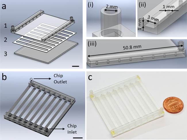
To overcome the challenges of 3D printing methods in microfluidic device fabrication for applications in biology and medicine, we utilized a hybrid manufacturing technique by combining 3D printing with laser micromachined lamination. Transparent microfluidic devices encompassing inlet, outlet, integrated uniform flow distribution manifolds, and fully embedded channels were fabricated and assembled to build intricate microdevices with eight parallel microchannels (Fig. 1). The new hybrid fabrication method allowed incorporation of the following key features to an advanced microfluidic system architecture: (i) increased design complexity in 3D, (ii) improved control over microflow in all three directions, (iii) transverse multilayer flow and precisely integrated flow distribution, and (iv) enhanced transparency for high resolution imaging and analysis. In addition, CD4+ T cells were captured from blood in the 3D printed device prototype to demonstrate the feasibility of cell isolation in the proposed system. Hybrid manufacturing approach can eliminate the need for costly and time-consuming clean room fabrication while overcoming the design limitations of the lamination method. This novel approach would allow fabrication of complex and customized 3D microfluidic devices incorporating transverse multilayer flow.
Fig. 1.
Hybrid manufacturing of a microfluidic platform using 3D printing and laser micromachining. (a) The microfluidic system is produced with a multiple layer lamination approach, by assembling; (1) a 3D printed top part encompassing inlets, outlets, and embedded manifolds for flow distribution, (2) a laser micromachined layer defining channel geometry, and (3) a glass substrate. Scale bar represents 10 mm length. The 3D printed top design includes; (i) inlets and outlets with 2 mm diameter, (ii) two manifolds of 50.8 mm length × 3 mm width × 1 mm height, and (iii) eight channel inlets and outlets with 1 mm diameter. (b) CAD design of the assembled 3D printed microfluidic device showing device inlet and outlet. Scale bar represents 10 mm length. (c) 3D printed microfluidic device is composed of eight parallel microchannels for processing of flow distributed from embedded manifolds.
2 Materials and Methods
2.1 Design and 3D Printing of Microfluidic Devices
Microfluidic devices were designed using SolidWorks (Solid-Works Corp., Waltham, MA), in a layer-by-layer approach (Fig. 1(a)). Structural design of the microfluidic system was composed of a glass substrate, a 3D printed top (encompassing inlet, outlet, and embedded manifolds), and a 250 μm thick laser micromachined middle layer defining the channel geometry (Fig. 1(a)). Design steps included the determination of channel width, length, height, manifold connections, and inlet/outlet port sizes and locations (Fig. 1(b)) to fabricate a fully functional prototype microfluidic device (Fig. 1(c)). The 3D printed top was composed of inlet and outlet ports (diameter of 2 mm), two manifolds (50.8 mm × 3 mm × 1 mm), and eight channel inlets and outlets (diameter of 1 mm). We 3D printed the designed microfluidic devices using PolyJet method and transparent VeroClear-RGD810 (Stratasys, Eden Prairie, MN) as the printing material. Objet 260 Connex (Stratasys, Eden Prairie, MN), a professional desktop 3D printer, was utilized which achieves 20–85 μm accuracy for features smaller than 50 mm. The process parameters for PolyJet are: 30 μm layer thickness by 42 μm X and Y axis resolution, minimum feature size for standard fabrication of 0.5 mm, standard tolerances 0.127 mm or ±0.0254 mm (whichever is greater). PolyJet system supports simultaneous printing of multiple materials with high precision, and transparent material deposition is especially useful for microfluidic device fabrication for applications in biology and medicine.
The VeroClear-RGD material has been successfully used for long-term cell culture [14] and analysis of blood cells [11], demonstrating the biocompatibility of VeroClear-RGD material. The VeroClear-RGD material has an approximate composition of isobornyl acrylate (15–30%), acrylic monomer (15–30%), urethane acrylate (10–30%), acrylic monomer (10–15%), epoxy acrylate (10–15%), acrylate oligomer (10–15%), and a photoinitiator (1–2%) [11]. The VeroClear material has the following properties: tensile strength of 50–65 MPa (ASTM D-638-03), modulus of elasticity of 2000–3000 MPa (ASTM D-638-04), flexural strength of 75–110 MPa (ASTM D-790-03), flexural modulus of 2200–3200 MPa (ASTM D-790-04), water absorption of 1.1–1.5% (ASTM D-570-98 24 hrs), Rockwell hardness of 73–76 Scale M (ASTM Scale M), and polymerized density of 1.18–1.19 (ASTM D792). This material is cured using ultraviolet (UV) light.
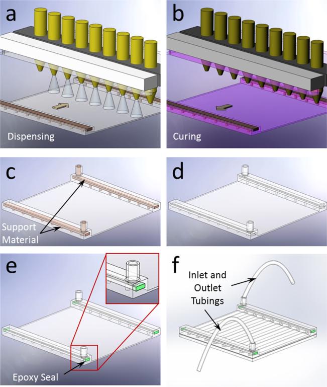
PolyJet printing involved a two-step process, in which the material was dispensed in the forward stroke first (Fig. 2(a)), and then the dispensed layer was cured in the return stroke (Fig. 2(b)). A secondary material was utilized to fill and support the hollow sections of the design during fabrication (Fig. 2(c)), which was then washed away in the postprocessing stage (Fig. 2(d)). The 3D printed part was then polished using an ECOMET 6 (Buehler, Waukegan Road, Lake Bluff, IL) variable speed grinder polisher at 200 rpm. Next, the micromachined channel layer was attached on a 50 mm × 50 mm glass slide. The open ends of the manifold were sealed (Fig. 2(e)) with epoxy (Devcon 5 min Epoxy, Devcon, Danvers, MA) and plastic tubing was attached to the manifolds to complete the assembly of the microfluidic device (Fig. 2(f)).
Fig. 2.
Fabrication process of the 3D printed microfluidic device. (a) Multiple nozzle dispenses structural and supporting filler materials in the forward stroke. (b) Dispensed material is cured with UV light in the return stroke. (c) After the completion of printing, microfluidic device accompanies filler support materials before the postprocessing. (d) Final product after postprocessing is shown without the filler material. (e) Open ends of the 3D printed manifold were sealed after washing out the supporting filler material. (f) Complete assembly of the microfluidic device is achieved with inlet and outlet tubing connections.
2.2 Laser Micromachining of Channel Layers
Middle channel layer of the microfluidic device was fabricated using a double sided adhesive (DSA) with a height of 250 μm. DSA layer was cut to accommodate eight 48 mm × 3.5 mm × 250 μm channels on a 2 in. × 2 in. glass slide, using a VersaLASER system (Universal Laser Systems, Inc., Scottsdale, AZ). For the fabrication of the microfluidic channel layer, the VersaLaser system was set to the following settings: the vector cutting was set to 35% (minimum: −50%, maximum: 50%), the vector performance was set to “Quality.” The process time for VersaLASER system varies with the above mentioned parameters. For the process parameters selected, the process time was approximately 35 seconds. The line thickness for the laser point was set to “Hair Line,” which results in the minimum possible laser point size, thus producing the least amount of heat. This process yields no residue as the adhesive is wrapped within polymer film. The channel layer was then attached to the glass substrate and assembled with the 3D printed top layer to form microfluidic devices with embedded manifolds (Fig. 2(f)).
2.3 Computational Fluid Dynamics (CFD) Analysis
We examined the designed microfluidic device with CFD analysis in terms of manifold and microchannel flow properties. COMSOL Multiphysics 4.3 (Burlington, MA) was used in these analyses. We used hexahedral swept meshes for the microchannel and tetrahedral elements to mesh the rest of the computational domain. Total number of mesh elements was 250,638. We simulated the domain for water flow at 25 °C using single phase laminar flow module. Pressure distribution and velocity profiles in manifold and channel subdomains were evaluated and presented.
2.4 Microfluidic Channel Visualization and Image Processing
An Olympus IX83 inverted motorized fluorescent microscope (Olympus Corp., Tokyo, Japan) with Olympus Cell Sense imaging and analysis software was used to obtain microscopic recordings in this study. Videos were recorded at 10 fps (frames per second) and converted to single frame images for further processing and analysis. To represent the flow of cells in channels, comparable size fluorescent microbeads with 10 μm diameter were utilized and imaged.
2.5 Microfluidic Geometry Characterization
Dimensions of the microfluidic channels were precisely determined by measuring the distance between channel edges for width and distance between top and bottom surfaces for height using the fully automated microscope stage and high resolution microscope camera (EXi Blue, QImaging Corp., Surrey, BC, Canada).
2.6 Microfluidic Channel Flow Velocity Analysis
Fluorescent microbeads (Polysciences, Warrington, PA) with 10 μm diameter were injected into the microfluidic device at a concentration of 430,000 beads/mL in distilled water for measurement of flow velocities and distribution among microchannels. Microbeads were introduced into the microfluidic device at 50 μL/min and 100 μL/min flow rates. Flowing microbeads in channels were visualized and recorded using the inverted microscope.
2.7 Selective Cell Isolation From Blood
Microchannels of the 3D printed device were functionalized with CD4 antibodies using a four-step surface chemistry for the specific capture of CD4+ T Cells. First, glass slides were cleaned by sonication in acetone and ethanol, dried with nitrogen, and treated under a UV ozone cleaner (Novascan PSDP-UV8T) for 10 mins at 110 °C. Immediately after this step, glass slides were dipped in ethanol and then immersed in (3-mercaptopropyl)trimethoxysilane (3-MPS) solution (4% v/v in ethanol) for 30 mins at room temperature. Glass slides were then dipped in ethanol, then immersed in N-g-maleimidobutyryloxysuccinimide ester solution (0.28% v/v in ethanol) for 15 mins at room temperature, and dried with nitrogen gas. After the assembly with 3D printed microfluidic top part and tubings, channels were flushed with phosphate buffered saline (PBS), Neutravidin solution (1 mg/mL) and incubated overnight at 4 °C. After the incubation, channels were flushed with PBS, biotinylated CD4 antibody solution (50 μg/mL), and incubated for an hour at 4 °C. Channels were rinsed with PBS before blood processing.
De-identified surplus blood samples were obtained from University Hospital's Hematology and Oncology Division under institutional review board approval. Before being introduced into the microfluidic device, blood samples were diluted 1:5 with flow cytometry staining (FCSB) buffer. Then, 2.5 mL of sample was flown into the device at 40 μL/min volumetric flow rate. After blood processing, channels were washed with FCSB buffer at a volumetric flow rate of 160 μL/min to remove nonadhered cells. Next, captured cells were stained with anti-CD4 antibody conjugated with Alexa Fluor 488, and imaged using a fluorescent microscope.
2.8 Statistical Analysis
Data obtained in this study were reported as mean ± standard deviation of the mean. Flow velocity distribution among the microchannels were statistically assessed (Minitab 16 software, Minitab, Inc., State College, PA) using analysis of variance (ANOVA) with Tukey's posthoc test for multiple comparisons (n = 8). Statistical significance was set at 95% confidence level for all tests (p < 0.05). Error bars in figures represent the standard deviation of the mean.
3 Results
3.1 Three-Dimensional Printing Based Hybrid Manufacturing of Microfluidic Devices
Using 3D printing and laser micromachined lamination (Figs. 1(a) and 1(b)), we built microfluidic devices with integrated inlet and outlet manifolds (Fig. 1(c)). Eight parallel microchannels enable enhanced throughput and add parallel sample processing capability to the microfluidic device for biological applications (Fig. 1(c)). In PolyJet 3D printing method (Figs. 2(a)–2(c)), the design of the printed part accommodated the washing of the support material in the postprocessing stage (Fig. 2(d)), which can be a significant challenge for embedded, intricate microfluidic channels. The hybrid layer-by-layer fabrication approach that we present here overcomes this challenge by limiting the use of supporting material in the manifolds, which were designed to have open ends (Figs. 2(d) and 2(e)). The presented approach allows the washing of the support material in the postprocessing stage and enables seamless integration with external systems (Fig. 2(f)).
3.2 Fabricated Device Structure
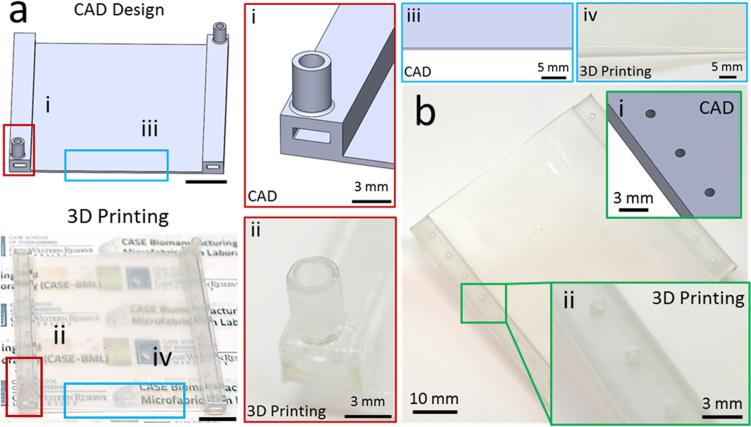
Devices fabricated with 3D printing resulted in transparent layers (Fig. 3(a)). Transparency is a crucial parameter in microfluidic cell analysis assays, where quantification and sensing is generally realized by optical means. In addition, inlet and outlet of the devices fabricated using 3D printing provided clear flow pathways as designed (Fig. 3(a)). Moreover, the features of the device were clear and sharp (Fig. 3(a)). Furthermore, bottom layer of the devices fabricated with 3D printing displayed a smooth finish (Fig. 3(b)). A smooth and flat surface is essential to achieve a tight seal and hence to prevent leaks in channels. After the assembly of 3D printed microfluidic device, geometry of the microchannels were evaluated by measuring channel height (Fig. 4(a)) and channel width (Fig. 4(b)). We observed a uniform microfluidic channel height (250 μm ± 4.9 μm, Fig. 4(a)), and width (3.75 mm ± 0.01 mm, Fig. 4(b)) between separate channels, which was in agreement with the CAD design. The uniformity of width and height of the fabricated microchannels showed that the utilized hybrid manufacturing method can produce multiple parallel microchannels with robust and repeatable geometrical properties.
Fig. 3.
Fabrication of the microfluidic device using 3D printing. The microfluidic devices fabricated with PolyJet printing are compared to the CAD design for performance evaluation. (a) PolyJet printing allowed fabrication of transparent microfluidic devices, while closely matching to the CAD design for (i and ii) inlet and outlet with clear flow pathways. (iii and iv) Moreover, edges of the base layer were clear and sharp as in the CAD design. Scale bars represent 10 mm length. (b) Surface evaluation of printed device in comparison to CAD design. (i and ii) Bottom layer of the 3D printed microfluidic device provided a smooth surface finishing.
Fig. 4.
3D printed microfluidic device provides uniform geometry in every microchannel. Microfluidic channel (a) height, and (b) width were uniform between every microchannel, with 250 μm ± 4.9 μm height and 3.75 mm ± 0.01 mm width. Error bars represent the standard deviation of the mean.
3.3 CFD Analysis of the Microfluidic Device
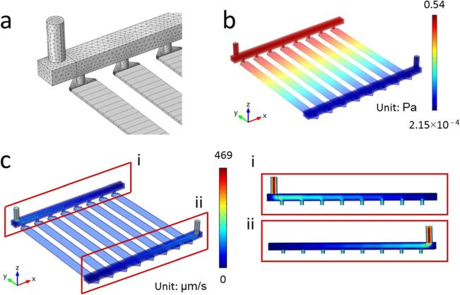
The flow characteristics inside the fabricated microfluidic device were analyzed using CFD analysis. We used hexahedral swept mesh for the microfluidic channel array and tetrahedral for the rest of the domain (Fig. 5(a)). The computational results revealed a highly uniform distribution of pressure (Fig. 5(b)), and velocity (Fig. 5(c)) within the designed microfluidic device among all eight channels. Furthermore, cross-sectional analysis of flow within the manifolds revealed a uniform and proportional distribution among all inlets and outlets (Fig. 5(c)).
Fig. 5.
CFD Analysis of the designed microfluidic device. (a) Grid distribution showing hexahedral mesh for the channel array and tetrahedral mesh for the rest of the rest of the domain. (b) Pressure and (c) velocity distribution for the domain showed uniform flow characteristics between microchannels. (i and ii) Velocity distribution at the manifolds and microchannel inlet and outlets.
3.4 CFD Analysis of Individual Microfluidic Channels
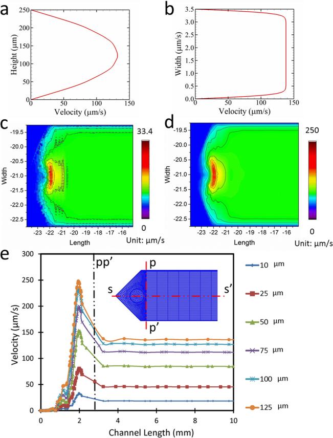
Analyses revealed that transverse velocity field along the length of a channel (Fig. 6(a)) had a parabolic flow profile, and the lateral velocity field along the width displayed a characteristic plug flow profile (Fig. 6(b)) within a channel. The velocity fluctuation within the microchannel inlets was assessed through contour plots at two planes: (i) at a plane 10 μm above the bottom of the channel (Fig. 6(c)), and (ii) at a plane 125 μm above the bottom of the channel, i.e., at the midplane (Fig. 6(d)). The results showed that the velocity fluctuation at the lower section of the channel had a higher irregularity compared to the midsection. Velocity profiles at multiple layers in the close vicinity of the inlet port showed that the flow velocity fluctuations dampen within the first 6% of the channel length (<3 mm), and the flow becomes quiescently laminar (Fig. 6(e)) after the first 3 mm of inlet. Similar disturbance at the velocity was observed to be prevalent at the other end of the microchannel where the flow exits the microchannel and enters the outlet manifold.
Fig. 6.
Velocity profile and flow distribution in the microfluidic channel. (a) Velocity profile along the height of the channel. (b) Velocity profile along the width of the channel. (c) Surface plot of velocity distribution at the channel at a plane 10 μm above the bottom surface. (d) Surface plot of velocity distribution at the channel at a plane 125 μm above the bottom surface. (e) Velocity in the channel along ss′ at different height of the channel.
3.5 Flow Imaging in Fabricated Microfluidic Channels
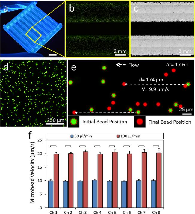
To measure flow velocity inside the microfluidic channels, we seeded fluorescent spherical microbeads of 10 μm diameter (Figs. 7(a)–7(c)), which is a typical size for most cell types in the blood circulation. Sequential images were collected during bead flow inside the microchannels and bead velocities were calculated by dividing the total displacement of an individual bead to the analysis time (Figs. 7(d) and 7(e)). We observed 10 μm/s and 20 μm/s bead flow velocities inside the microchannels for 50 μl/min and 100 μl/min syringe pump flow rates (Fig. 7(e)). Microbead velocities were significantly higher at 100 μl/min flow rate compared to 50 μl/min flow rate for every channel. There was no statistically significant difference between microbead velocities in different microchannels for the same flow rates (one way ANOVA test with Tukey's posthoc test for multiple comparisons, n = 8, p < 0.05). The results of flow imaging were observed to agree with the CFD analysis results in terms of flow velocity fields within the channels. Furthermore, these results showed that 3D printed device with embedded manifold can uniformly distribute transverse flow from the device inlet to multiple parallel microchannels in a different layer.
Fig. 7.
Homogenous flow distribution in microchannels of the 3D printed microfluidic device. (a) 3D printed microfluidic device prototype. Scale bar represents 10 mm length. (b) Fluorescent and (c) phase contrast images of microfluidic channels injected with fluorescent microbeads delineating microchannels. (d)–(f) Flow velocity in microchannels are determined by seeding (d) fluorescent microbeads of 10 μm diameter. Sequential images of flowing microbeads were recorded using an inverted fluorescent microscope and a charge coupled device (CCD) camera. (e) Bead velocities are calculated by dividing the total displacement of an individual bead to the elapsed time. (f) Microbead velocities are determined for each microchannels at 50 μl/min and 100 μl/min flow rates supplied to the device. There was no statistically significant difference between microbead velocities in different microchannels at the same flow rates. Microbead velocities were significantly higher in all microchannels at 100 μl/min flow rate compared to 50 μl/min flow rate. The horizontal lines between individual groups represent statistically significant difference based on one way ANOVA test with Tukey's posthoc test for multiple comparisons (n = 8, p < 0.05). Error bars represent the standard deviation of the mean.
3.6 CD4+ T Cell Capture From Blood
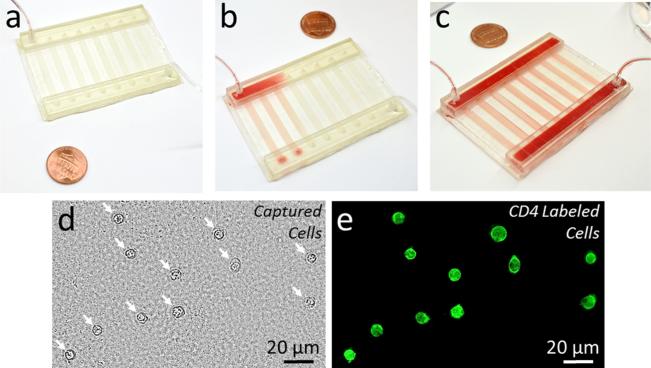
We validated the microfluidic system fabricated with a hybrid manufacturing approach for isolation of phenotypic cell subpopulations by selectively capturing CD4+ T cells from blood (Fig. 8). Blood sample injected into the microfluidic device showed uniform distribution among different channels and manifolds (Figs. 8(a)–8(c)). CD4+ cells were selectively captured from the processed blood sample with greater than 95% specificity as shown via bright field and fluorescent imaging of all captured cells and CD4 labeled cells, respectively (Figs. 8(d) and 8(e)).
Fig. 8.
Capture of CD41 T cells from blood using a hybrid manufactured microfluidic device. (a) and (b) Blood sample is injected into the 3D printed microfluidic device through the inlet port and the inlet manifold. (c) Injected blood sample was uniformly distributed to all channels through the integrated manifold. (d) and (e) CD41 T cells were successfully captured from the processed blood sample. (d) Bright field image of all captured cells from blood is shown. White arrows indicate captured cells. (e) Captured cells were labeled with a CD4 antibody conjugated fluorescent label to validate the specific capture of the targeted CD41 T cells.
4 Discussion
Efficiency and throughput has been a challenge in isolation and manipulation of rare cells using microfluidic devices [15]. Any cell type with a concentration of less than 1000 cells per mL is considered as a rare cell type, such as circulating tumor cells (CTCs), circulating fetal cells, and stem cells [16]. In the case of tumor cells circulating in blood stream, there are 1–100 CTCs per 3–6 × 10⁹ blood cells. Extremely low number of these cells necessitates processing of large volumes (> 10 mL) of samples to obtain a reasonable number of cells and/or genetic material. Thus, high efficiency and throughput is especially critical in isolation and analysis of rare cell types, and acquisition of biological materials for proteomic/genomic analyses [5,9,17]. Large isolation surface area is required for high-throughput operation, which can be achieved by either utilizing long channels, or multiple short channels in a parallel configuration. However, using long channels increases sample processing time. Thus, multiple parallel channels have been widely employed to increase the throughput of microfluidic devices [3,5]. The use of parallel channels requires homogeneous distribution of flow to every channel, to prevent channel to channel variations in cell capture efficiency and specificity. Parallel microfluidic channel designs in 3D configurations with uniform flow conditions via an integrated manifold stand out as a promising solution to this challenge. Manifolds can be fabricated as an integral part of the device as an internal or external component.
The CFD analysis of the microfluidic device is significant in terms of investigating the flow stagnation within the domain. Such flow stagnation poses difficulties in washing out of nonadhered blood cells after the cell adhesion process is completed. The CFD analysis identifies the areas of flow stagnation for the designed microfluidic device, thus helps with the optimization of the channel design. The channel surface roughness is a critical parameter to consider while analyzing the flow behavior within channels. In the designed microfluidic device, the bottom channel surface was glass and the top surface was the 3D printed part. The glass surface was considered to be smooth. We hand finished the surface of the 3D printed part using an ECOMET 6 variable speed grinder polisher using 200 rpm to ensure uniform surface roughness for all the channels. Based on these facts and for the simplicity of numerical analysis, effect of surface roughness was not incorporated in the CFD analysis.
Development of microfluidic technologies followed the footsteps of microfabrication techniques, originally developed by the semiconductor industry. Thus, earlier studies in microfluidics heavily relied on photolithographic pattern fabrication on a silicon template and soft lithography using PDMS. Soft lithography is the most widely applied technique in manufacturing of microfluidic systems. However, soft lithography based microfluidic device fabrication methods require clean room facilities and highly skilled labor. In soft lithography, microchannel top parts, fabricated through a costly and time-consuming clean room process, are assembled with a glass slide to complete the microfluidic channels. This approach generally limits the fabricated device in a 2D plane and renders 3D channel configurations or 3D flow manipulation hard to achieve. Utilization of discrete elements and modules has been reported in the literature to overcome the limitations [12,13]. In this study, we are proposing an alternative approach to soft lithography, replacing the clean room microfabrication with 3D printing and DSA bonding. We believe this approach can be an enabling technique for fabrication of complex and customized 3D microfluidic devices incorporating transverse multilayer flow.
Even though 3D printing has evolved rapidly and starting to be widely applied in the field of tissue engineering, microfluidics has yet to benefit from this additive manufacturing method due to limitations in design complexity, transparency, surface quality, resolution, and fabrication of microscale hollow and void sections. In this study, we have utilized a novel hybrid approach integrating 3D printing with lamination to overcome these limitations. Three-dimensional printing of complex microfluidic devices with enclosed microchannels and integrated uniform flow distribution manifolds made of transparent materials were not achievable with most 3D printing methods. PolyJet based 3D printing has z-resolution high enough to create a smooth transition between layers. Moreover, PolyJet method utilizes a washable supporting material in fabrication process to accommodate hollow sections in the design, which is an excellent feature that enables printing of enclosed cavities and voids. Washing off of support material in postprocessing stage can be challenging for fully enclosed microscale cavities, which can be addressed with a hybrid fabrication approach, as presented here. Another major advantage of 3D printing is the use of transparent materials for microfluidic devices. Hybrid manufacturing of microfluidic devices integrating 3D printing with lamination approach may open new venues for 3D printing for microfluidic applications.
5 Conclusions
Advanced additive manufacturing technologies, such as 3D printing, are critical in minimizing the fabrication steps and assembly complexities. Here, we utilized a hybrid manufacturing technique by combining 3D printing and laser micromachined lamination approach to offer a new way of fabricating complex 3D microfluidic devices. Using 3D printing, we fabricated microfluidic devices integrated with uniform flow distribution manifolds, and embedded channels reducing fabrication complexities, as well as allowing more complex designs, including flow in all three directions and transverse multilayer flow. Integrating 3D printing to fabrication processes has the potential to improve standardization, fast and single-step production, and user-independent manufacturing of microfluidic systems, which are current challenges in the field. Assembly of 3D printed parts together with laser micromachined layers via lamination approach can also be used for cost and labor efficient fabrication of standardized microfluidic discrete elements and modules. Overall, hybrid manufacturing approaches, such as the one presented here, hold great potential for microfluidic device fabrication.
Acknowledgment
This work was supported in part by Grant No. 2013126 from the Doris Duke Charitable Foundation, Clinical and Translational Science Collaborative (CTSC) Annual Pilot Award (funded by the National Center for Advancing Translational Sciences and the National Institutes of Health), the Coulter-Case Translational Research Partnership Award, and Steven Garverick Memorial Innovation Incentive Award.
Contributor Information
Yunus Alapan, Biomanufacturing and Microfabrication Laboratory, Mechanical and Aerospace, Engineering Department, Case Western Reserve University, Cleveland, OH 44106, yxa81@case.edu.
Muhammad Noman Hasan, Biomanufacturing and Microfabrication Laboratory, Mechanical and Aerospace Engineering Department, Case Western Reserve University, Cleveland, OH 44106, mnh38@case.edu.
Richang Shen, Biomanufacturing and Microfabrication Laboratory, Mechanical and Aerospace Engineering Department, Case Western Reserve University, Cleveland, OH 44106, rxs580@case.edu.
Umut A. Gurkan, Biomanufacturing and Microfabrication Laboratory, Mechanical and Aerospace Engineering Department, Biomedical Engineering Department, Orthopedics Department, Case Western Reserve University, Cleveland, OH 44106; Advanced Platform Technology Center, Louis Stokes Cleveland Veterans Affairs Medical Center, Cleveland, OH 44106.
References
- 1.Moon S, Gurkan UA, Blander J, Fawzi WW, Aboud S, Mugusi F, Kuritzkes DR, Demirci U. Enumeration of CD4+ T-Cells Using a Portable Microchip Count Platform in Tanzanian HIV-Infected Patients. PLoS One. 2011;6(7):e21409. doi: 10.1371/journal.pone.0021409. [DOI] [PMC free article] [PubMed] [Google Scholar]
- 2.Wang S, Tasoglu S, Chen PZ, Chen M, Akbas R, Wach S, Ozdemir CI, Gurkan UA, Giguel FF, Kuritzkes DR, Demirci U. Micro-a-Fluidics ELISA for Rapid CD4 Cell Count at the Point-of-Care. Sci. Rep. 2014;4:3796. doi: 10.1038/srep03796. [DOI] [PMC free article] [PubMed] [Google Scholar]
- 3.Stott SL, Hsu CH, Tsukrov DI, Yu M, Miyamoto DT, Waltman BA, Rothenberg SM, Shah AM, Smas ME, Korir GK, Floyd FP, Jr., Gilman AJ, Lord JB, Winokur D, Springer S, Irimia D, Nagrath S, Sequist LV, Lee RJ, Isselbacher KJ, Maheswaran S, Haber DA, Toner M. Isolation of Circulating Tumor Cells Using a Microvortex-Generating Herringbone-Chip. Proc. Natl. Acad. Sci. U. S. A. 2010;107(43):18392–18397. doi: 10.1073/pnas.1012539107. [DOI] [PMC free article] [PubMed] [Google Scholar]
- 4.Alapan Y, Little JA, Gurkan UA. Heterogeneous Red Blood Cell Adhesion and Deformability in Sickle Cell Disease. Sci. Rep. 2014;4:7173. doi: 10.1038/srep07173. [DOI] [PMC free article] [PubMed] [Google Scholar]
- 5.Kotz KT, Xiao W, Miller-Graziano C, Qian WJ, Russom A, Warner EA, Moldawer LL, De A, Bankey PE, Petritis BO, Camp DG, II, Rosenbach AE, Goverman J, Fagan SP, Brownstein BH, Irimia D, Xu W, Wilhelmy J, Mindrinos MN, Smith RD, Davis RW, Tompkins RG, Toner M. Clinical Microfluidics for Neutrophil Genomics and Proteomics. Nat. Med. 2010;16(9):1042–1047. doi: 10.1038/nm.2205. [DOI] [PMC free article] [PubMed] [Google Scholar]
- 6.Gurkan UA, Tasoglu S, Akkaynak D, Avci O, Unluisler S, Canikyan S, MacCallum N, Demirci U. Smart Interface Materials Integrated With Microfluidics for On-Demand Local Capture and Release of Cells. Adv. Healthcare Mater. 2012;1(5):661–668. doi: 10.1002/adhm.201200009. [DOI] [PMC free article] [PubMed] [Google Scholar]
- 7.Gurkan UA, Anand T, Tas H, Elkan D, Akay A, Keles HO, Demirci U. Controlled Viable Release of Selectively Captured Label-Free Cells in Microchannels. Lab Chip. 2011;11(23):3979–3989. doi: 10.1039/c1lc20487d. [DOI] [PMC free article] [PubMed] [Google Scholar]
- 8.Vickers DA, Chory EJ, Murthy SK. Separation of Two Phenotypically Similar Cell Types Via a Single Common Marker in Microfluidic Channels. Lab Chip. 2012;12(18):3399–3407. doi: 10.1039/c2lc40290d. [DOI] [PubMed] [Google Scholar]
- 9.Nagrath S, Sequist LV, Maheswaran S, Bell DW, Irimia D, Ulkus L, Smith MR, Kwak EL, Digumarthy S, Muzikansky A, Ryan P, Balis UJ, Tompkins RG, Haber DA, Toner M. Isolation of Rare Circulating Tumour Cells in Cancer Patients by Microchip Technology. Nature. 2007;450(7173):1235–U1210. doi: 10.1038/nature06385. [DOI] [PMC free article] [PubMed] [Google Scholar]
- 10.Waldbaur A, Rapp H, Lange K, Rapp BE. Let There Be Chip-Towards Rapid Prototyping of Microfluidic Devices: One-Step Manufacturing Processes. Anal. Methods. 2011;3(12):2681–2716. [Google Scholar]
- 11.Gross BC, Erkal JL, Lockwood SY, Chen C, Spence DM. Evaluation of 3D Printing and Its Potential Impact on Biotechnology and the Chemical Sciences. Anal. Chem. 2014;86(7):3240–3253. doi: 10.1021/ac403397r. [DOI] [PubMed] [Google Scholar]
- 12.Lee KG, Park KJ, Seok S, Shin S, Kim DH, Park JY, Heo YS, Lee SJ, Lee TJ. 3D Printed Modules for Integrated Microfluidic Devices. RSC Adv. 2014;4(62):32876–32880. [Google Scholar]
- 13.Bhargava KC, Thompson B, Malmstadt N. Discrete Elements for 3D Microfluidics. Proc. Natl. Acad. Sci. U. S. A. 2014;111(42):15013–15018. doi: 10.1073/pnas.1414764111. [DOI] [PMC free article] [PubMed] [Google Scholar]
- 14.Esch MB, Prot JM, Wang YI, Miller P, Llamas-Vidales JR, Naughton BA, Applegate DR, Shuler ML. Multi-Cellular 3D Human Primary Liver Cell Culture Elevates Metabolic Activity Under Fluidic Flow. Lab Chip. 2015;15(10):2269–2277. doi: 10.1039/c5lc00237k. [DOI] [PMC free article] [PubMed] [Google Scholar]
- 15.Tasoglu S, Gurkan UA, Wang S, Demirci U. Manipulating Biological Agents and Cells in Micro-Scale Volumes for Applications in Medicine. Chem. Soc. Rev. 2013;42(13):5788–5808. doi: 10.1039/c3cs60042d. [DOI] [PMC free article] [PubMed] [Google Scholar]
- 16.Dharmasiri U, Witek MA, Adams AA, Soper SA. Microsystems for the Capture of Low-Abundance Cells. Annu. Rev. Anal. Chem. (Palo Alto Calif.) 2010;3:409–431. doi: 10.1146/annurev.anchem.111808.073610. [DOI] [PubMed] [Google Scholar]
- 17.Plouffe BD, Kniazeva T, Mayer JE, Jr., Murthy SK, Sales VL. Development of Microfluidics as Endothelial Progenitor Cell Capture Technology for Cardiovascular Tissue Engineering and Diagnostic Medicine. FASEB J. Off. Publ. Fed. Am. Soc. Exp. Biol. 2009;23(10):3309–3314. doi: 10.1096/fj.09-130260. [DOI] [PMC free article] [PubMed] [Google Scholar]


