Abstract
Purpose:
Transcranial focused ultrasound (FUS) shows great promise for a range of therapeutic applications in the brain. Current clinical investigations rely on the use of magnetic resonance imaging (MRI) to monitor treatments and for the registration of preoperative computed tomography (CT)-data to the MR images at the time of treatment to correct the sound aberrations caused by the skull. For some applications, MRI is not an appropriate choice for therapy monitoring and its cost may limit the accessibility of these treatments. An alternative approach, using high frequency ultrasound measurements to localize the skull surface and register CT data to the ultrasound treatment space, for the purposes of skull-related phase aberration correction and treatment targeting, has been developed.
Methods:
A prototype high frequency, hemispherical sparse array was fabricated. Pulse-echo measurements of the surface of five ex vivo human skulls were made, and the CT datasets of each skull were obtained. The acoustic data were used to rigidly register the CT-derived skull surface to the treatment space. The ultrasound-based registrations of the CT datasets were compared to the gold-standard landmark-based registrations.
Results:
The results show on an average sub-millimeter (0.9 ± 0.2 mm) displacement and subdegree (0.8° ± 0.4°) rotation registration errors. Numerical simulations predict that registration errors on this scale will result in a mean targeting error of 1.0 ± 0.2 mm and reduction in focal pressure of 1.0% ± 0.6% when targeting a midbrain structure (e.g., hippocampus) using a commercially available low-frequency brain prototype device (InSightec, 230 kHz brain system).
Conclusions:
If combined with ultrasound-based treatment monitoring techniques, this registration method could allow for the development of a low-cost transcranial FUS treatment platform to make this technology more widely available.
Keywords: focused ultrasound, transcranial therapy, blood–brain barrier, image registration
1. INTRODUCTION
Focused ultrasound (FUS) is a promising technology that has shown exciting potential for brain disorders. To date, transcranial FUS has been used for noninvasive surgery to treat chronic pain,1,2 essential tremor,3,4 Parkinson’s disease,5 obsessive compulsive disorder6 and glioblastoma.7,8 These investigations have been based on the thermal ablation of targeted brain tissue using FUS and have been guided by magnetic resonance imaging (MRI), using MRI thermometry to measure temperature elevations during treatment. However, there are nonthermal, cavitation-mediated applications of FUS that are being investigated preclinically, such as transient opening of the blood–brain barrier (BBB) for targeted drug delivery9,10 or sonothrombolysis for the treatment of ischemic stroke.11,12 For these interventions MRI may be useful for assessing treatment outcome, but is not well suited for real-time monitoring of cavitation processes. Additionally, MRI is not widely accessible and could be prohibitively expensive if frequent treatments are required.
Ultrasound (US)-based monitoring and control of BBB-opening has been demonstrated in preclinical models,13,14 and it has been shown that cavitation activity can be mapped in the brain during BBB opening.15–17 These studies suggest that low-cost, ultrasound-guided treatment platforms for cavitation-mediated brain therapies may be a viable option for bringing these technologies to routine clinical practice. The final aspect of such a system is a method to correct for the sound aberrations caused by geometry and heterogeneity of the skull bone.18,19 This is necessary in order to correct the transmit focus,20 but also for eliminating image distortion when mapping cavitation activity through the skull.17,21 The gold-standard approach is to use computed tomography (CT)-derived density and geometry information taken from preoperative patient CT data to calculate the necessary phase and amplitude corrections to produce a sharp ultrasound focus through the skull.22,23 In current MRI-guided treatments, the preoperative CT images are registered with the MR-images during the treatment planning stage to bring the CT data into the US treatment space.7 A stereotactic frame is used to ensure that the patient’s head does not move during the treatment, but the frame is not typically in place for the preoperative CT imaging and thus registration to the intraoperative MRI is necessary for targeting and to compute the skull-induced aberration correction terms. We propose that as an alternative, an array of high frequency US elements within the US therapy array could be used to register the preoperative CT data to the treatment space for aberration correction and targeting. In combination with US cavitation monitoring and control, this could eliminate the need for MRI during these treatments. This could greatly reduce the costs associated with these treatments and improve access to them as MRI might only be needed post-treatment to confirm treatment effect, or not at all if other imaging modalities (e.g., contrast CT) are substituted. Although targeting and aberration correction could be performed without MRI using stereotactic registration if a permanent frame was in position for the preoperative CT, the proposed approach would allow for the CT to be taken well in advance of the intervention for treatment planning purposes and would also allow the use of a temporary frame or a frameless approach that would improve the patient’s comfort.
Here we demonstrate the feasibility of US registration of CT data using ex vivo human skullcaps and a 128-element sparse hemispherical array.
2. MATERIALS AND METHODS
2.A. Ultrasound array and imaging
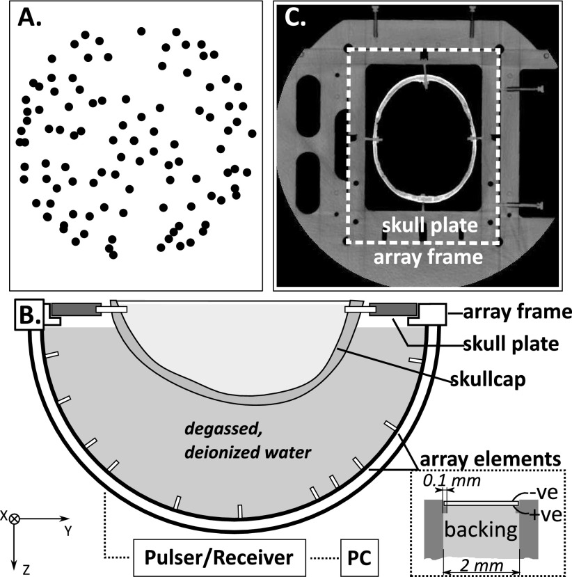
128 lead zirconate titanate (PZT-5) elements were fabricated and installed on the inner surface of a 30 cm diameter Lucite hemispherical dome (Global Plastics Services, Calasis, ME, USA). The elements were squares with dimensions of 2 × 2 mm2 and were diced from larger PZT plates using a DISCO dicing saw (DISCO Corporation, Ota-ku, Tokyo, Japan). The elements had center frequencies of approximately 11 MHz. Rectangular holders (3 × 3 × 10 mm3) were rapid prototyped to hold each element. A cross section view of an element and holder is shown in the inset of Fig. 1(B). A small amount of super glue was applied to the edges of the elements to fix them to small (0.1 mm wide) supporting ledges on each holder. The elements were backed using a 3:1 (by weight) mixture of PZT powder (Del Piezo Specialties, LLC, West Palm Beach, FL, USA) and epoxy (301 epoxy, Epoxy Technology, Inc., Billerica, MA, USA) in order to improve the transducer bandwidth. The backing layer, which filled the rectangular holder, was approximately 1 cm thick and the bottom surface was angled to prevent the reflection of sound back towards the element. The impulse response was measured for each element by measuring the pulse-echo from an acrylic plate, yielding an average bandwidth (mean ± s.d.) of 3.5 ± 2.3 MHz.
FIG. 1.
(A) Top projection of the element locations; (B) experimental setup, inset: cross section view of one array element showing the construction; (C) CT slice showing the array frame and skull plate.
The elements were distributed across the entire hemisphere with some randomization to their placement [Fig. 1(A)]. The element locations were determined via triangulation of signals received from an acoustic source (1 mm diameter PZT element, center frequency = 0.6 MHz) moved around the field with a three-axis positioner, and verified through comparison with CT images of the array.
The experimental setup is shown in Fig. 1. A frame for holding the ex vivo skullcaps was rigidly mounted to the imaging array. The frame included four reference markers that could be seen on CT. The positions of the markers in the array coordinate space were recorded using the 3-axis positioner. The frame allowed repeatable placement of ex vivo human skullcaps mounted onto mating acrylic plates. Five different skullcaps were tested. The ex vivo human skullcaps were degassed in a vacuum jar for 2 h prior to acoustic measurements. The array was filled with degassed, deionized water and a skullcap was placed in the array. The US imaging was performed with a multichannel transmit/receive system (Verasonics, Inc., Redmond, WA, USA). The elements were excited one at a time with an 11.25 MHz, single cycle burst, and the reflected signal was recorded and averaged over five acquisitions. The sampling rate was 45 MHz.
To test how the skin and scalp might affect this technique, one set of measurements was conducted using an ex vivo scalp from the same donor as the skullcap. Both samples were degassed for 3 h prior to the experiment. Measurements (32 averages) were acquired with and without the scalp in place. The cling film was used to hold the scalp against the skull. The measurements were made through an area of the scalp with minimal hair and which was tight against the skull with the lowest possibility of a gap between the tissues.
2.B. CT imaging
The water was drained from the array, and the array and skullcap were imaged in a CT scanner (Aquilon ONE, Toshiba America Medical Systems, Inc., Tustin, CA, USA) using a standard head CT protocol. The voxel dimensions were 0.78 × 0.78 × 1 mm3 and the image matrix was 512 × 512, with a total of 135–161 slices covering the skullcap, plate, and markers on the array. One skull (Skull #5) was imaged three times, fully removing it from the array frame between each set of images, to assess the positional error associated with the frame. The locations of the frame reference markers were measured for each image stack in the 3D Slicer (http://www.slicer.org).24
2.C. Data processing
The data were processed offline using matlab (Mathworks, Natick, MA, USA). The outer surface of the skull was segmented from the CT data using built-in edge detection functions in matlab to generate a binary mask. The resulting surface was defined in 3D by a series of vertices and faces. The CT data were rotated 180° to bring them into rough alignment with the ultrasound coordinate space as an initial transform estimate.
Next the ultrasound data were analyzed. For each element, i, the time of flight Δti was determined by identifying the rising edge of the echo wavefront. To achieve this, the data were digitally filtered with a fourth order Butterworth bandpass filter (0.1–20 MHz) and the Hilbert transform was taken to extract the signal envelope. The rising edge of the signal envelope was located and followed backwards to the closest inflection point. Δti was determined as the time associated with the location of the inflection point.
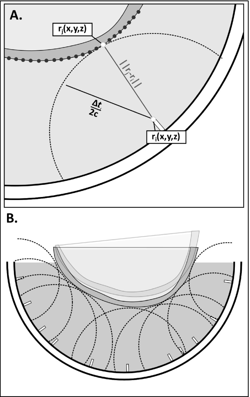
The distance to the point on the skull where the first reflection of the sound occurred was determined from the time of flight. As illustrated in Fig. 2(A), a point on the skull surface could then be assumed to fall on a spherical surface centered about the element i and having radius, Δti/(2c), where c is the speed of sound in water. For all elements, the skull position within the dome is that where the skull sits on the multiple spherical bounding surfaces, as shown in Fig. 2(B), and can be solved using a closest-points based approach.25 It should be noted that this solution does not depend on the assumption of spherical spreading and, in fact, directionality is expected given the dimensions and frequency of the elements. Rather, the use of spherical bounding surfaces was chosen because (1) the solution will hold regardless of the directivity of the elements, and (2) the spherical surfaces can be easily represented analytically, making the resulting optimization less computationally expensive than defining each bounding surface as the intersection of the spherical surface and the element beam.
FIG. 2.
(A) Illustration showing the spherical bounding surface centered at element ri and having radius Δti/2c, and the skull surface positioned so that the distance between the bounding surface and a point, j, on the skull surface is minimized; (B) illustration showing the optimal orientation of the skull, where the distance between the spherical bounding surface and a point on the skull surface is minimized for all elements. The transparent overlay illustrates a suboptimal iteration of the optimization.
Given the CT and ultrasound data, the transformation matrix T(x), where {x} is a vector containing three Euler angles and displacements along the three Cartesian directions, that transforms the CT data into the ultrasound coordinate space can be determined. The solution takes the form of an optimization problem, where {x} is the vector of values that minimizes the cost function,
| (1) |
where Ri(x) is the distance between the spherical control surface for element i and the closest vertex on the skull surface, and Pi(x) is a penalty function. Ri(x) can be expressed as
| (2) |
where rj is a vector describing the location of a point {j} on the skull surface, ri is a vector describing the location of element i, and ||.|| represents the Euclidean norm. The penalty function Pi(x) is double valued, being 0 if the skull sits above the spherical bounding surface, and having the value of the distance the skull has penetrated the surface, times a weighting factor a, (default = 0.5), if any point on the skull surface lies closer to element i than the radius of the bounding surface determined from the ultrasound measurements. Mathematically this can be expressed as
| (3) |
| (4) |
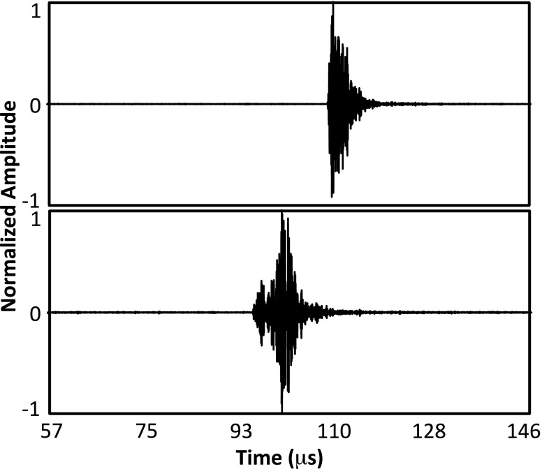
The optimization was solved in matlab in two steps. First, an unconstrained solver was used to solve for the displacements to center the CT-derived data within the ultrasound space. Then, a constrained solver was used to solve the full transformation matrix using the solution to the first stage as the initial starting vector and restricting rotations about and translations along each axis to ±3° and ±3 mm, respectively. For both optimization stages, the cost function was evaluated at each iteration for the 64 elements providing the best fit to the skull surface. This was done to avoid errors in the calculation of Δti for some elements biasing the optimization results. For example, for elements near the top of the dome, scattering from the water surface sometimes resulted in an artificially shortened Δti. Additionally, the strong variability in the impulse response of the in-house fabricated array elements (mean ± s.d. bandwidth = 3.5 ± 2.3 MHz) combined with skull geometry-attributable differences in the detected echoes across the channels complicated the US data processing (Fig. 3).
FIG. 3.
Example skull echo data from two different array elements showing significant differences in the sharpness of the rising edge.
2.D. Numerical simulations
As a gold-standard, the transformation matrix to bring the CT data into the US space was calculated from the positions of the markers on the array frame in the CT images and the measured locations on the array. The transformation matrix calculated based on the landmarks, TL, was solved for using the method described by Horn.26 The difference between the US determined transformation matrix and TL was determined by solving the system of equations,
| (5) |
for the transformation matrix TΔ, and decomposing it into three Euler angles and three displacements. Here, Rskull is a matrix containing the coordinates of all of the points (vertices) rj on the skull surface.
A previously developed21 transcranial ultrasound propagation model based on ray-acoustics was employed to assess the transmit focusing error resulting from imperfections in the US-based registration. The location of the hippocampus within the brain region of five triangulated skull meshes was targeted in silico using a clinical transcranial phased array (ExAblate 4000, InSightec, Haifa, Israel) applicator (1024 elements, 1 × 1 cm2, 30 cm diameter array aperture). The phases required to target the hippocampus were determined from the US-registered data and were applied to the landmark-registered (gold-standard) skull configurations to determine the impact of the misalignment on trans-skull focusing. Two factors were expected to contribute to the overall focusing error: the anatomical target being shifted on the planning (US-registered) images relative to its true position, and the cranial bone being shifted in the calculation of the skull-related phase corrections. The simulations were performed at 230 and 650 kHz, and both the peak pressure and positional error were calculated relative to the case where no registration error was present.
3. RESULTS
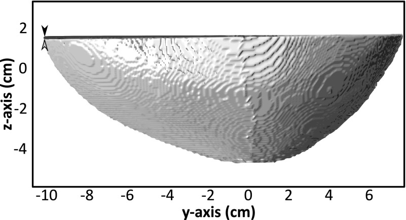
Of the 128 elements, 96 detected strong echoes from the skull. The remaining 32 elements produced low or no signal. In some cases this may have been due to non-normal angles of incidence on the skull resulting in the sound being reflected away from the element. The optimization algorithm was run using the data from the 96 elements producing strong signals, and at each iteration summing the cost function across the 64 elements yielding the best fit, as described in Sec. 2. An example US-registered skull is shown compared to the landmark-registered data in Fig. 4.
FIG. 4.
Example of landmark-registered (black) and US-registered (gray) data from Skull #1 in the reference frame of the US array. The arrowheads highlight a small rotational error.
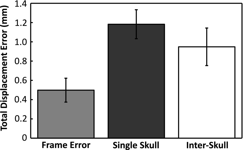
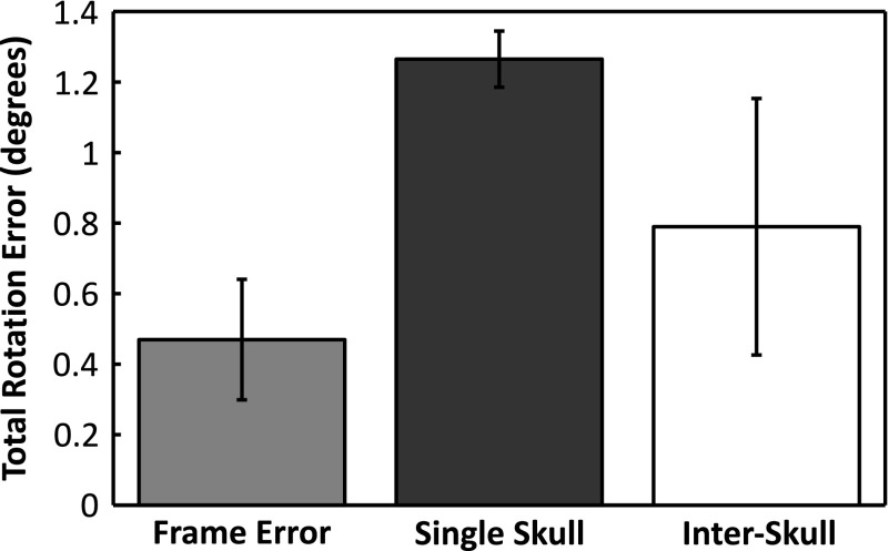
Figures 5 and 6 show the absolute displacement errors and absolute rotational errors associated with the experimental fixtures (frame error), across multiple CT datasets from the same skull (Skull #5 mean) and across multiple different skulls (interskull mean). The frame error was calculated using the landmarks on the array frame to register the repeated CT data sets from Skull #5 to the same coordinate space. The skull plate was then registered across the data sets using holes drilled into the plate as references. The frame errors (0.5 ± 0.1 mm; 0.5° ± 0.2°) thus represent the possible differences in the true orientation of the skull between the US and CT measurements. The displacement and rotation errors associated with repeat measurements of one skull were determined by registering the same US data to the three different CT stacks obtained for Skull #5. With average errors of 1.2 ± 0.1 mm and 1.3° ± 0.1°, Skull #5 had the highest registration error of all the skulls. The low intraskull standard deviations show that the registration errors did not vary greatly across different CT datasets of the same skull. Across all skulls (using the mean values for Skull #5), sub-millimeter (0.9 ± 0.2 mm) and subdegree errors (0.8° ± 0.4 ˚) were obtained on average, but larger standard deviations were observed, particularly for the rotational error.
FIG. 5.
Average displacement error (mean ± s.d.) associated with the array frame (placement reproducibility), multiple measurements of the same skull (Skull #5), and measurements across multiple skulls (interskull).
FIG. 6.
Average rotation error (mean ± s.d.) associated with the array frame (placement reproducibility), multiple measurements of the same skull (Skull #5), and measurements across multiple skulls (interskull).
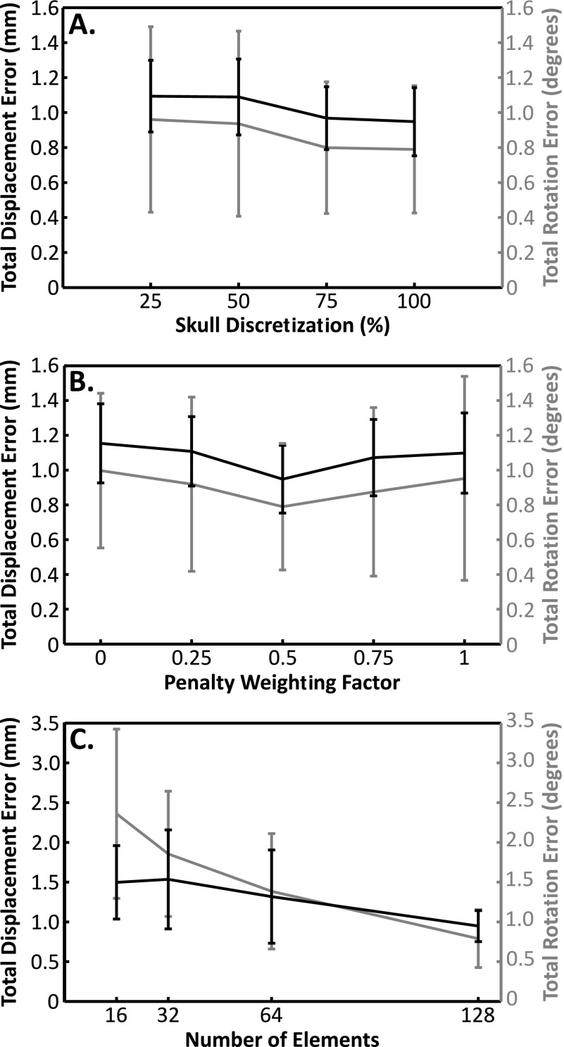
Figure 7 shows the dependency of this registration scheme on different algorithm parameters averaged across the five skulls. In Fig. 7(A) the impact of the skull surface discretization from the CT data is shown. The results are expressed in terms of a percentage of the initial number of vertices, with 100% corresponding to no refinement of the surface (10.2 ± 0.6 × 10⁴ vertices, 0.3 ± 0.1 mm2 face area). The results show only a small increase in the mean errors with decreasing discretization. Even when the number of vertices is reduced to 25% of the original number, there is no significant difference in the average errors (displacement: p = 0.35, rotation: p = 0.30; two-tailed, paired t-test) although the standard deviation of the displacement errors increases by 46%, showing greater variability in the results. In Fig. 7(B), the effect of the penalty weighting factor, a, is shown. Only a modest effect was seen, with a slight but not significant (displacement: p = 0.23, rotation: p = 0.31), improvement in the average errors across the skulls at the default value of a = 0.5, compared with a = 0.
FIG. 7.
Average (mean ± s.d.) displacement (black) and rotation (gray) errors across the five skulls (A) as a function of the skull discretization (surface refinement to 75%, 50%, and 25% of the initial number of vertices); (B) as a function of the weighting factor in the penalty function; (C) as a function of the number of elements.
Figure 7(C) illustrates the errors as a function of array elements. For the full array (128 elements), only 75% (96) of the elements produced usable signals, and the optimization cost function was summed across 50% (64). To examine the impact of smaller arrays, subarrays were simulated, using 64, 32, or 16 of the elements from the full array, sampled evenly across the array. The same ratios as the full array were maintained, i.e., for a nominal 64-element array, 25% of the elements were discarded due to poor signal quality (48 elements remaining) and the cost function was summed across 50% (32 elements). Reducing the number of elements by half increased the displacement and rotation errors by 39% and 75% respectively, but without statistical significance (displacement: p = 0.19, rotation: p = 0.14). Although the displacement error never quite reached a statistically significant difference from the full array (p = 0.06 for 16 elements), the rotational error increased significantly when the array was reduced 32 elements (p = 0.01) and was threefold higher for 16 elements than for the full array.
The results of the numerical simulations are summarized in Table I. Using the registration errors obtained for each skull, a mean targeting error of 1.0 ± 0.2 mm at 230 kHz (1.0 ± 0.2 mm at 650 kHz) occurred, while the focal pressure was reduced by 1.0% ± 0.6% at 230 kHz (1.1% ± 0.4% at 650 kHz) on average. A comparable mean targeting error (0.99 ± 0.39 mm) has been reported using the current MRI-guided approach for transcranial focused ultrasound thermal brain ablation.28
TABLE I.
Simulation results. Focal pressure and positional shift due to skull-array misregistration are reported relative to the ideal case of perfect registration. Results are shown for 230 and 650 kHz. The targeting error is the shift of the anatomical target due to the registration error.
| Skull | Pressure ratio (%) (230 kHz/650 kHz) | Focal shift (mm) (230 kHz/650 kHz) | Targeting error (mm) |
|---|---|---|---|
| 1 | 100/99 | 0.6/0.7 | 0.7 |
| 2 | 99/99 | 0.8/0.9 | 0.8 |
| 3 | 99/99 | 0.9/1.0 | 1.0 |
| 4 | 99/99 | 1.2/1.0 | 1.0 |
| 5(1) | 99/99 | 1.0/1.0 | 1.0 |
| 5(2) | 99/99 | 1.1/1.2 | 1.2 |
| 5(3) | 99/98 | 1.2/1.3 | 1.3 |
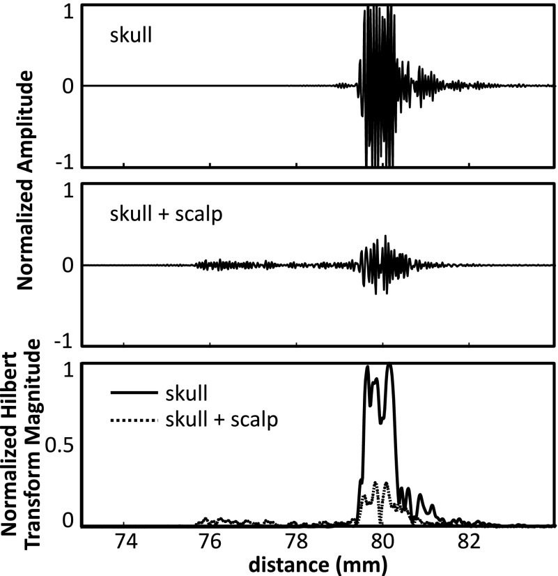
Figure 8 shows example echoes from a single channel on one skull, with and without the scalp. Although attenuated, the echo from the skull bone can be clearly seen. Also shown are the magnitudes of the Hilbert transform for each case, showing a clear rising edge at the tissue-skull interface. From the echo data, the scalp thickness at this location is estimated to be ∼3.7 mm. This is within the reported range of scalp thickness for adults (3–5 mm).29 At the cut edge, the scalp used in this study was measured with Vernier calipers to be 7.5 mm thick at its thickest point.
FIG. 8.
Example echoes from a skull with and without the scalp in place are shown in the top two panels. The bottom panel shows the corresponding Hilbert transform magnitudes for the two cases.
4. DISCUSSION
The results of this study show that this method can register preoperative CT-data to the US coordinate space with accuracy on the order of 1 mm/1°. For practical implementation it appears that 128 elements are sufficient, even considering that some may not provide useable signals, as was the case here. When the number of elements was reduced by half, there was no significant difference in the mean errors, but the standard deviations (displacement and rotation) were more than doubled, suggesting that the full 128-element array should be used. For the element size employed here (2 × 2 mm2), 128 elements would only account for 0.4% of the surface area of a 30 cm diameter hemispherical array and thus the available area for therapy elements, and receive elements dedicated to passive imaging, would not be greatly affected. Although we envision the use of three subarrays (therapy, passive imaging and skull localization), the total cost for the multichannel driving and receiving electronics could be kept reasonable by using switching so that the localization array could use the hardware already in place for a therapy array with integrated passive imaging. It should be noted that although we used a paired t-test for the statistical analysis, which can be used with small group sizes, the limited number of measurements analyzed here is still somewhat small for statistical comparisons.
In the future, more complex algorithms that use triangulation of signals received by surrounding elements may be used to recover information from some of the elements where the transmitted sound is not reflected back to the element but scattered elsewhere in the dome. The element positions could also be optimized based on average skull geometry to minimize dropped channels and should be investigated in the design of future arrays. Additionally, this study used in-house fabricated elements, which varied strongly in their response. More robust fabrication techniques and quality assurance would reduce the number of dropped channels and simplify the data analysis.
The parameter analysis demonstrates that the optimization scheme is tolerant to moderate changes in the parameters and that the discretization is sufficiently dense. The penalty weighting function had less impact on the registration results than expected. The objective of this function was to give preference to solutions where all of the points lay outside the skull by a small amount, over solutions where some of the points lay just inside the skull, and some just outside. The two cases would result in similar values of the cost function but the latter case could have an associated rotational error. The inclusion of only half of the elements in the cost function after calculation of the distance and penalty values for each may have reduced the impact of this parameter by excluding elements with high penalty values. In this study we used a relatively simple method to robustify the registration by including only the best 50% of the elements. More sophisticated methods using M-estimators (e.g., the biweight30) could provide a better solution and may be necessary to achieve a good solution in the presence of the overlying scalp. There are many different options for estimators, all of which perform differently in the presence of noise and outliers,31 and the suitability of these estimators for this application should be investigated in the future. In this study we used, rising-edge detection to identify the time-to-echo. This approach required several waveform averages to ensure good detection and still became inaccurate for waveforms with low SNR. A more robust method that should be investigated in future work would be to use a matched filter to identify the echoes, with a unique filter template for each channel based on the individual elements’ impulse responses. This approach may be particularly useful in separating the echoes from the scalp and skull.
The method described is one possible implementation to register CT images of the skull to discrete ultrasound measurements of the skull surface. This method could also work to register other 3D data sets of the skull, such as MRI, to ultrasound data. Several modifications to the methods are possible. For example, the cost function was described in terms of a mean squared error, which allowed for faster convergence, but could also be expressed in terms of a linear sum or with individual element weightings. Additionally, Ri(x) and mi were expressed in terms of the minimum of an absolute value, or the distance between the skull vertex or face and the closest point. Alternatively, these could be expressed as the absolute value of the minimum of the signed distance. This could be used in place of, or in conjunction with, the penalty term to address penetration of the skull surface through the spherical bounding surfaces.
The objective of this study was to develop this registration method to use with cavitation-mediated therapies. However, it could also have potential application in thermal therapies if ultrasound-based treatment monitoring techniques such as local harmonic imaging32 or ultrasound thermometry33 can be robustly implemented transcranially. Additionally, because the ultrasound imaging is fast and the data from all 128 elements can be acquired on the order of milliseconds, even if the elements are excited one at a time, there is the potential to further develop the technique presented here to track head motion during the treatment, thus removing the need for a stereotactic frame. The acquisitions can be accelerated by transmitting from multiple elements at the same time. It may also be possible to use different frequency transmissions from each of the elements to allow more overlapping transmissions. In the second step of our registration we used a constrained optimization. In practice, a noninvasive frame27,34 may be used during the CT imaging and treatment to provide a rough initial alignment of the two data sets prior to optimizing the registration and would allow the use of a constrained solver.
In this study the high frequency array was not integrated with a therapy array and thus we were not able to experimentally investigate the targeting errors resulting from registration errors. Our in silico results are promising and show errors on the order of 1 mm, corresponding to 26% of the lateral −6 dB focal width at 230 kHz and 74% at 650 kHz (values estimated from ray-acoustic simulations in water). These targeting errors are reasonable for applications such as targeted drug delivery, where the treatment region will in most cases be much larger than a single focal volume, and treatment margins are not as critical as functional surgery applications like the treatment of essential tremor.3,4 Our study assumes that the position of the skull during the CT and US measurements was the same such that the landmark-based registration and US-based registration should ideally be identical. However, our results with multiple CTs of Skull #5 show that there is a positioning error associated with the frame. Thus the targeting errors from our in silico results most likely overestimate the targeting error compared to what would be measured experimentally with a therapy array. An important next step to this work is the implementation of this method with a combined high frequency/therapy array so that the targeting errors can be fully experimentally characterized.
The small pressure reductions observed in silico due to the misregistration of the skull can be attributed to the large size of the individual array elements (1 × 1 cm) compared to the acoustic wavelengths simulated, which caused the beam from a given element to propagate through a large portion of the skull, differing only slightly between the misregistered case and the case with no error. Indeed, the intersection between the surface area over which the beam penetrated the outer (inner) skull surface for the two cases was 96.0% ± 1.6% (94.7% ± 1.6%) at 230 kHz and 98.3% ± 1.5% (97.4% ± 0.9%) at 650 kHz. Therefore the focusing errors appear to arise primarily from the shift of the anatomical target and, for the therapeutic transducer simulated, the errors in calculating the skull correction terms have minimal impact.
A limitation of this study is that only the skullcaps, without scalp, were used. This is not expected to affect the CT segmentation given the high contrast between bone and soft tissue. However, the analysis of the US data, particularly in identifying the position of the skull echo, may require modification. Our preliminary measurements through the scalp show that the tissue/scalp interface can still be identified. The scalp used in this study was separate from the bone and was held in place to ensure that there was no air or water gap between the tissues. It was not possible to guarantee good coupling over the entire aperture so the full registration technique could not be tested with the scalp. Future studies will examine the impact of the soft tissue layers in greater detail. In this study the receiver elements were excited using single-cycle bursts at 11.25 MHz. In the future an impulse may be used in order to shorten the pulse length and improve the imaging resolution. Because the intended function of this array was to localize the skull surface, and not to image through the skull bone, we were able to use elements with an 11 MHz center frequency. Although we did not optimize the transmit frequency in this study, the choice of frequency will be more important in the presence of the scalp when sufficient resolution is needed to separate the echoes. Naturally the method may also use other frequencies that provide the needed precision in the localization.
5. CONCLUSION
An ultrasound-based registration algorithm was developed to register CT skull data to an ultrasound treatment coordinate space. Our results show sub-millimeter and subdegree registration errors, producing only modest targeting errors in silico. The method is a key component in the development of a low-cost, transcranial ultrasound treatment platform.
ACKNOWLEDGMENTS
The authors would like to thank Dr. Yuexi Huang for his help obtaining the CT data, Lucy Deng for assistance with the ultrasound measurements, and Angela Ip, Nathan Lim, and Cassandra Tyson for their help fabricating the array. The support for this work was provided by the National Institutes of Health under Grant No. R01- EB003268, the Canada Research Chair Program, and the W. Garfield Weston Foundation.
CONFLICT OF INTEREST DISCLOSURE
M. A. O’Reilly, R. M. Jones, and K. Hynynen are listed as co-inventors on a patent application related to the methods described in this paper.
REFERENCES
- 1.Martin E., Jeanmonod D., Morel A., Zadicario E., and Werner B., “High-intensity focused ultrasound for noninvasive functional neurosurgery,” Ann. Neurol. (6), 858–861 (2009). 10.1002/ana.21801 [DOI] [PubMed] [Google Scholar]
- 2.Jeanmonod D., Werner B., Morel A., Michels L., Zadicario E., Schiff G., and Martin E., “Transcranial magnetic resonance imaging-guided focused ultrasound: Noninvasive central lateral thalamotomy for chronic neuropathic pain,” Neurosurg. Focus (1), E1 (2012). 10.3171/2011.10.FOCUS11248 [DOI] [PubMed] [Google Scholar]
- 3.Lipsman N., Schwartz M. L., Huang Y., Lee L., Sankar T., Chapman M., Hynynen K., and Lozano A. M., “MR-guided focused ultrasound thalamotomy for essential tremor: A proof-of-concept study,” Lancet Neurol. (5), 462–468 (2013). 10.1016/S1474-4422(13)70048-6 [DOI] [PubMed] [Google Scholar]
- 4.Elias W. J., Huss D., Voss T., Loomba J., Khaled M., Zadicario E., Frysinger R. C., Sperling S. A., Wylie S., Monteith S. J., Druzgal J., Shah B. B., Harrison M., and Wintermark M., “A pilot study of focused ultrasound thalamotomy for essential tremor,” N. Engl. J. Med. (7), 640–648 (2013). 10.1056/NEJMoa1300962 [DOI] [PubMed] [Google Scholar]
- 5.Magara A., Bühler R., Moser D., Kowalski M., Pourtehrani P., and Jeanmonod D., “First experience with MR-guided focused ultrasound in the treatment of Parkinson’s disease,” J. Ther. Ultrasound , 11 (2014). 10.1186/2050-5736-2-11 [DOI] [PMC free article] [PubMed] [Google Scholar]
- 6.Jung H. H., Kim S. J., Roh D., Chang J. G., Chang W. S., Kweon E. J., Kim C.-H., and Chang J. W., “Bilateral thermal capsulotomy with MR-guided focused ultrasound for patients with treatment-refractory obsessive-compulsive disorder: A proof-of-concept study,” Mol. Psychiatry , 1205–1211 (2014). 10.1038/mp.2014.154 [DOI] [PubMed] [Google Scholar]
- 7.McDannold N., Clement G. T., Black P., Jolesz F., and Hynynen K., “Transcranial magnetic resonance imaging- guided focused ultrasound surgery of brain tumors: Initial findings in 3 patients,” Neurosurgery (2), 323–332 (2010), discussion 332.10.1227/01.NEU.0000360379.95800.2F. 10.1227/01.NEU.0000360379.95800.2F [DOI] [PMC free article] [PubMed] [Google Scholar]
- 8.Coluccia D., Fandino J., Schwyzer L., O’Gorman R., Remonda L., Anon J., Martin E., and Werner B., “First noninvasive thermal ablation of a brain tumor with MR-guided focused ultrasound,” J. Ther. Ultrasound , 17 (2014). 10.1186/2050-5736-2-17 [DOI] [PMC free article] [PubMed] [Google Scholar]
- 9.Hynynen K., McDannold N., Vykhodtseva N., and Jolesz F. A., “Noninvasive MR imaging-guided focal opening of the blood–brain barrier in rabbits,” Radiology (3), 640–646 (2001). 10.1148/radiol.2202001804 [DOI] [PubMed] [Google Scholar]
- 10.Choi J. J., Pernot M., Small S. A., and Konofagou E. E., “Noninvasive, transcranial and localized opening of the blood–brain barrier using focused ultrasound in mice,” Ultrasound Med. Biol. (1), 95–104 (2007). 10.1016/j.ultrasmedbio.2006.07.018 [DOI] [PubMed] [Google Scholar]
- 11.Culp W. C., Flores R., Brown A. T., Lowery J. D., Roberson P. K., Hennings L. J., Woods S. D., Hatton J. H., Culp B. C., Skinner R. D., and Borrelli M. J., “Successful microbubble sonothrombolysis without tissue-type plasminogen activator in a rabbit model of acute ischemic stroke,” Stroke (8), 2280–2285 (2011). 10.1161/STROKEAHA.110.607150 [DOI] [PMC free article] [PubMed] [Google Scholar]
- 12.Burgess A., Huang Y., Waspe A. C., Ganguly M., Goertz D. E., and Hynynen K., “High-intensity focused ultrasound (HIFU) for dissolution of clots in a rabbit model of embolic stroke,” PLoS One (8), e42311 (2012). 10.1371/journal.pone.0042311 [DOI] [PMC free article] [PubMed] [Google Scholar]
- 13.O’Reilly M. A. and Hynynen K., “Blood–brain barrier: Real-time feedback-controlled focused ultrasound disruption by using an acoustic emissions-based controller,” Radiology (1), 96–106 (2012). 10.1148/radiol.11111417 [DOI] [PMC free article] [PubMed] [Google Scholar]
- 14.Arvanitis C. D., Livingstone M. S., Vykhodtseva N., and McDannold N., “Controlled ultrasound-induced blood–brain barrier disruption using passive acoustic emissions monitoring,” PLoS One (9), e45783 (2012). 10.1371/journal.pone.0045783 [DOI] [PMC free article] [PubMed] [Google Scholar]
- 15.Arvanitis C. D., Livingstone M. S., and McDannold N., “Combined ultrasound and MR imaging to guide focused ultrasound therapies in the brain,” Phys. Med. Biol. (14), 4749–4761 (2013). 10.1088/0031-9155/58/14/4749 [DOI] [PMC free article] [PubMed] [Google Scholar]
- 16.O’Reilly M. A., Jones R. M., and Hynynen K., “Three-dimensional transcranial ultrasound imaging of microbubble clouds using a sparse hemispherical array,” IEEE Trans. Biomed. Eng. (4), 1285–1294 (2014). 10.1109/tbme.2014.2300838 [DOI] [PMC free article] [PubMed] [Google Scholar]
- 17.Jones R. M., O’Reilly M. A., and Hynynen K., “Experimental demonstration of passive acoustic imaging in the human skull cavity using CT-based aberration corrections,” Med. Phys. (7), 4385–4400 (2015). 10.1118/1.4922677 [DOI] [PMC free article] [PubMed] [Google Scholar]
- 18.Fry F. J. and Barger J. E., “Acoustical properties of the human skull,” J. Acoust. Soc. Am. (5), 1576–1590 (1978). 10.1121/1.381852 [DOI] [PubMed] [Google Scholar]
- 19.Pichardo S., Sin V. W., and Hynynen K., “Multi-frequency characterization of the speed of sound and attenuation coefficient for longitudinal transmission of freshly excised human skulls,” Phys. Med. Biol. (1), 219–250 (2011). 10.1088/0031-9155/56/1/014 [DOI] [PMC free article] [PubMed] [Google Scholar]
- 20.Hynynen K. and Jolesz F. A., “Demonstration of potential noninvasive ultrasound brain therapy through an intact skull,” Ultrasound Med. Biol. (2), 275–283 (1998). 10.1016/S0301-5629(97)00269-X [DOI] [PubMed] [Google Scholar]
- 21.Jones R. M., O’Reilly M. A., and Hynynen K., “Transcranial passive acoustic mapping with hemispherical sparse arrays using CT-based skull-specific aberration corrections: A simulation study,” Phys. Med. Biol. (14), 4981–5005 (2013). 10.1088/0031-9155/58/14/4981 [DOI] [PMC free article] [PubMed] [Google Scholar]
- 22.Clement G. T. and Hynynen K., “A non-invasive method for focusing ultrasound through the human skull,” Phys. Med. Biol. (8), 1219–1236 (2002). 10.1088/0031-9155/47/8/301 [DOI] [PubMed] [Google Scholar]
- 23.Aubry J. F., Tanter M., Pernot M., Thomas J. L., and Fink M., “Experimental demonstration of noninvasive transskull adaptive focusing based on prior computed tomography scans,” J. Acoust. Soc. Am. (1), 84–93 (2003). 10.1121/1.1529663 [DOI] [PubMed] [Google Scholar]
- 24.Fedorov A., Beichel R., Kalpathy-Cramer J., Finet J., Fillion-Robin J.-C., Pujol S., Bauer C., Jennings D., Fennessy F., Sonka M., Buatti J., Aylward S., Miller J. V., Pieper S., and Kikinis R., “3D slicer as an image computing platform for the quantitative imaging network,” Magn. Reson. Imaging (9), 1323–1341 (2012). 10.1016/j.mri.2012.05.001 [DOI] [PMC free article] [PubMed] [Google Scholar]
- 25.Besl P. J. and McKay N. D., “A method for registration of 3-D shapes,” IEEE Trans. Pattern Anal. Mach. Intell. (2), 239–256 (1992). 10.1109/34.121791 [DOI] [Google Scholar]
- 26.Horn B. K. P., “Closed-form solution of absolute orientation using unit quaternions,” J. Opt. Soc. Am. A (4), 629–642 (1987). 10.1364/josaa.4.000629 [DOI] [Google Scholar]
- 27.Moser D., Zadicario E., Schiff G., and Jeanmonod D., “MR-guided focused ultrasound technique in functional neurosurgery: Targeting accuracy,” J. Ther. Ultrasound , 3 (2013). 10.1186/2050-5736-1-3 [DOI] [PMC free article] [PubMed] [Google Scholar]
- 28.Hori H., Moretti G., Rebora A., and Crovato F., “The thickness of human scalp: Normal and bald,” J. Invest. Dermatol. (6), 396–399 (1972). 10.1111/1523-1747.ep12540633 [DOI] [PubMed] [Google Scholar]
- 29.Kafadar K., “The efficiency of the biweight as a robust estimator of location,” J. Res. Natl. Bur. Stand. (2), 105–116 (1983). 10.6028/jres.088.006 [DOI] [PMC free article] [PubMed] [Google Scholar]
- 30.Mirza M. J. and Boyer K. L., “Performance evaluation of a class of M-estimators for surface parameter estimation in noisy range data,” IEEE Trans. Rob. Autom. (1), 75–85 (1993). 10.1109/70.210797 [DOI] [Google Scholar]
- 31.Curiel L., Chopra R., and Hynynen K., “In vivo monitoring of focused ultrasound surgery using local harmonic motion,” Ultrasound Med. Biol. (1), 65–78 (2009). 10.1016/j.ultrasmedbio.2008.07.001 [DOI] [PMC free article] [PubMed] [Google Scholar]
- 32.Lai C.-Y., Kruse D. E., Caskey C. F., Stephens D. N., Sutcliffe P. L., and Ferrara K. W., “Noninvasive thermometry assisted by a dual-function ultrasound transducer for mild hyperthermia,” IEEE Trans. Ultrason., Ferroelectr., Freq. Control (12), 2671–2684 (2010). 10.1109/tuffc.2010.1741 [DOI] [PMC free article] [PubMed] [Google Scholar]
- 33.Theodorou K., Kappas C., and Tsokas C., “A new non-invasive and relocatable immobilization frame for fractionated stereotactic radiotherapy,” Radiother. Oncol. (3), 313–317 (1998). 10.1016/S0167-8140(98)00015-2 [DOI] [PubMed] [Google Scholar]
- 34.Sayer F. T., Sherman J. H., Yen C.-P., Schlesinger D. J., Kersh R., and Sheehan J. P., “Initial experience with the extend system: A relocatable frame system for multiple-session gamma knife radiosurgery,” World Neurosurg. (5–6), 665–672 (2011). 10.1016/j.wneu.2010.12.051 [DOI] [PubMed] [Google Scholar]


