Significance
The rapid growth of data volume demands faster and denser storage devices. The noncoplanar swirling spin texture, known as magnetic skyrmion, has potential application in future memory devices. To realize such applications, it is essential to understand the properties of individual skyrmion in patterned nanoelements. While quite a number of theoretical efforts have been made in this field, direct experimental demonstration in such a real modeling system is a challenge. Here, we report the direct visualization of skyrmion cluster states in FeGe nanodisks. We determine the common relationship among the temperature, magnetic field, and disk size. These results have an immediate implication for designing future skyrmion-based devices.
Keywords: skyrmion, Lorentz TEM, spintronics, FeGe
Abstract
Magnetic skyrmion is a nanosized magnetic whirl with nontrivial topology, which is highly relevant for applications on future memory devices. To enable the applications, theoretical efforts have been made to understand the dynamics of individual skyrmions in magnetic nanostructures. However, directly imaging the evolution of highly geometrically confined individual skyrmions is challenging. Here, we report the magnetic field-driven dynamics of individual skyrmions in FeGe nanodisks with diameters on the order of several skyrmion sizes by using Lorentz transmission electron microscopy. In contrast to the conventional skyrmion lattice in bulk, a series of skyrmion cluster states with different geometrical configurations and the field-driven cascading phase transitions are identified at temperatures far below the magnetic transition temperature. Furthermore, a dynamics, namely the intermittent jumps between the neighboring skyrmion cluster states, is found at elevated temperatures, at which the thermal energy competes with the energy barrier between the skyrmion cluster states.
The complex spin configurations in helimagnets have attracted considerable attention recently, with the topologically stable particle-like spin texture with a size down to the nanoscale, namely magnetic skyrmion, as the focus of interest (1). Magnetic skyrmion is characterized as a nanoscale topological particle producing unconventional spin electronic phenomena (2, 3) that holds great promise for future spintronic devices, including racetrack memory (4), magnetic random access memory, and magnetic sensors (1). Essentially, such schemes rely on the controllable formation and manipulation of individual skyrmions at nanostructured elements with various shapes such as disks, stripes, or wires (5–7). Investigation of skyrmions in confined geometries has therefore become one of the major topics in the field of skyrmion physics (5–10).
Unlike ordinary magnetic vortices in microsized soft magnetic disks due to the minimization of the dipolar energy (11), the key ingredient of stabilizing skyrmions in helimagnets is the antisymmetry Dzyaloshinskii−Moriya (DM) interactions originating from the broken inversion symmetry (12). The competition of the DM coupling with ferromagnetic exchange interaction results in periodic helical ground state in helimagnets. Under the action of a magnetic field and temperature, these magnetic helices transfer into skyrmion crystal with triangular lattice configuration, and finally to the field-polarized ferromagnetic state. Notably, both ferromagnetic and DM couplings occur among the neighboring spins and belong to short-range interaction. Thus, it was demonstrated theoretically that skyrmions cluster states, characterized by certain arrangements of limited skyrmions, still persist even in submicrometer objects (8, 13). There, the long-range lattice form of skyrmions in 2D or bulk helimagnets is broken, but a short-ranged ordering with specific geometrical symmetries still remains, and the number of skyrmions in the cluster state can be continuously tuned by the application of a magnetic field. Because a single skyrmion is a twisted magnetic object with nontrivial topology, the creation or annihilation of an individual skyrmion is expected to be associated with a quantized transition (14). Recent measurement of magnetoresistance (MR) on an ultrathin MnSi nanowire provides such an indication of the quantized processes (15). However, direct real-space observations of these phase transitions in submicrometer helimagnets have not been reported and remain elusive.
In this work, we demonstrate the formation and evolution of skyrmion cluster states in FeGe nanodisks visualized by high-resolution Lorentz transmission electron microscopy (TEM). The field-driven cascading phase transition of skyrmion cluster states has been observed at both low and high temperatures. In addition, intermittent jumps between skyrmion cluster states, referred to as telegraph noise (16), have been noticed at elevated temperatures near the Curie temperature Tc.
Results
Magnetic Field-Driven Cascading Phase Transition of the Skyrmion Cluster States at Low Temperatures.
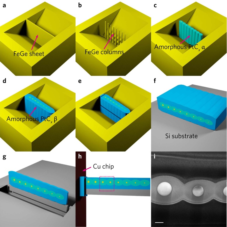
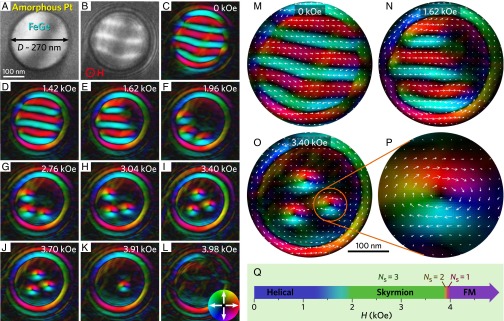
FeGe nanodisks were fabricated by the top-down method from bulk (Fig. S1). To reduce the interfacial Fresnel fringes in the Lorentz TEM images, the outer size-tunable nanodisks were encircled by a layer of amorphous platinum-carbon alloy PtCx (17) by use of the focused ion beam (FIB) technique. We first select a nanodisk with a diameter of D ≈ 270 nm, about 3 times larger than the featured helical period, λ ≈ 70 nm (18), to demonstrate the phase transitions between different skyrmion cluster states. A representative TEM image of the nanodisk is shown in Fig. 1A. An external magnetic field, H, is applied perpendicular to the disk plane with its direction pointing upward (marked as a red circled dot). Fig. 1B shows the intact magnetic contrast in ground state under zero magnetic field cooling conditions at the temperature T = 100 K, where the dark and light stripes represent the different planar magnetic moment distributions. By using the magnetic transport-of-intensity equation (TIE) analysis of the Lorentz TEM data (19), the in-plane components of the spin textures in the disk are constructed, as shown in Fig. 1C. Obviously, the Lorentz TEM images reveal a distorted helical ground state with four turns (Fig. 1 C and E). The period of the helix is about 68 nm, similar to the value in bulk λ ≈ 70 nm (18). However, the spatial confinement effect in the lateral direction yields an incomplete helix around the disk edge due to the specific form of the boundary conditions (20, 21).
Fig. S1.
Schematic procedure for fabricating FeGe nanodisks by using the FIB-SEM dual-beam system (Helios NanoLab 600i; FEI) equipped with a GIS, and Omniprobe 200+ micromanipulator. The whole process is shown schematically in eight steps for A–I: (A) Following the standard TEM specimen preparation procedure (40), a thin FeGe sheet with a thickness of ∼1 μm was carved on the surface of a polycrystalline FeGe bulk using the FIB milling technique. (B) The FeGe sheet was cut into circular columns with different diameters by FIB using annular patterns. (C) Using the GIS system, a layer of amorphous PtCx was deposited on the FeGe columns by the electron beam-assisted chemical vapor deposition technique. This PtCx coating works as protection of the FeGe nanocolumns for nanomanipulation processes and also reduces the Fresnel fringe at the edge of the disk for the Lorentz TEM study. (D) Further deposition of amorphous PtCx layer by ion beam-assisted chemical vapor deposition to fasten the samples. (E) A U-shaped cut was made from the sheet by FIB milling. (F) The sheet of FeGe nanocolumns surrounded by amorphous PtCx was transferred to a clean surface of silicon and laid down by an Omniprobe 200+ micromanipulator. (G) Using the standard TEM specimen preparation procedure, a slice consisting of FeGe nanodisks in various sizes was fabricated by FIB milling. (H) The slice was transferred to a TEM Cu chip using the micromanipulator, and then was thinned to the desired thickness. (I) TEM image of the nanodisk sample depicted in the dashed box in H. (Scale bar, 200 nm.)
Fig. 1.
Variations of spin texture with magnetic field in a 270-nm FeGe nanodisk at T = 100 K. (A) TEM image of the FeGe nanostripe surrounded by an amorphous PtCx layer. (B) The intact magnetic contrast in ground state under underfocused conditions of Lorentz TEM with a defocus value of −192 μm. The magnetic field is applied perpendicular to the stripe plane. (C–L) Magnetic-field dependence of the spin texture at (C) 0 kOe, (D) 1.42 kOe, (E) 1.62 kOe, (F) 1.96 kOe, (G) 2.76 kOe, (H) 3.04 kOe, (I) 3.40 kOe, (J) 3.70 kOe, (K) 3.91 kOe, and (L) 3.98 kOe. The color wheel in L indicates the direction and strength of in-plane magnetization at each point. For clarity, some typical spin textures in C, D, and I are zoomed in M, N, and O, respectively. (P) A single skyrmion. The white arrows represent the in-plane magnetization at each point. (Q) The phase diagram in H space. Ns, skyrmion numbers.
When a magnetic field is applied, the distorted helical state rapidly adjusts its spin orientation. At H ≈ 1.42 kOe, it transfers into a confined helix with three turns, with period remaining the featured value λ ≈ 70 nm (Fig. 1D) (18). With further increase of the magnetic field, the helix shrinks and eventually changes into three elongated skyrmions, i.e., bimerons (22), positioned along the edge (Fig. 1 E and N). Meanwhile, the remaining spins around the edge form a big vortex according to theoretical prediction and simple geometry analysis, although the Fresnel fringe partially smears out the real magnetic contrasts of edge vortex (8, 13, 20, 21). At H ≈ 1.96 kOe, the elongated skyrmions shrink into circles and assemble along the edge (Fig. 1F), indicating the attractive interaction among them (8, 17).
Once the skyrmions are formed around the edge, the elevated magnetic fields shrink these individual skyrmions and drive them gradually toward the interior of the nanodisk, due to repulsions between edge spins and skyrmions (Fig. 1 G–J) (4, 17). Finally, this triskyrmion cluster with triangular arrangement is formed in a wide interval of magnetic fields (1.96 kOe < H < 3.70 kOe), although the position of each individual skyrmion in the cluster can adjust correspondingly with the varied H (23). At H ≈ 3.91 kOe, two skyrmions annihilate instantaneously almost at the same time (Fig. 1K), leaving one skyrmion sitting nearly at the center of the disk to minimize the skyrmion−edge interaction (4). The single-skyrmion state is eventually terminated at H ≈ 3.98 kOe (Fig. 1L). The magnetic field intervals for hosting cluster states with skyrmion numbers Ns = 1 are much smaller than that of Ns = 3 (Fig. 1Q). These results are consistent with recent experimental observations on thin MnSi nanowires by MR measurements (15), in which the magnetic field intervals of hosting maximum number of skyrmions is always wider than those with if the same dynamical procedure is followed. By contrast, this observation is quite different from the theoretical calculation that the magnetic intervals of hosting different skyrmion clusters are comparable (8, 13). These differences probably come from the fact that the theoretical model only considers the equilibrium states (13), and the magnetization dynamics of skyrmions were not included.
Magnetization Dynamics of Skyrmion Cluster States at High Temperature.
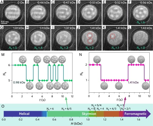
The field-driven discrete transition of skyrmion cluster states persists at elevated temperatures for T < Tc. Because the thermal fluctuation promotes the formation of skyrmions (14, 24), for the 270-nm disk increases from 3 at T = 100 K to 6 at T = 220 K, as shown in Fig. 2D. The corresponding magnetic field-driven evolution of the spin textures is displayed in Fig. 2 A‒L. At H ≈ 0 Oe, the distorted helical ground state shows a similar spin configuration to that at T = 100 K. At H ≈ 0.47 kOe, a skyrmion is isolated from the spin helices, bringing out a mixed state composed of bimerons, skyrmions, and spin helices (Fig. 2C). With further increase of the magnetic field, the mixed state transits to six skyrmions (Fig. 2D). This magnetization process follows previously reported results in 2D films, including FeGe (18), Fe0.5Co0.5Si (19), and numerical calculation (13). In this case, one skyrmion lies in the center of the disk, while five other skyrmions circle around, forming a pentagon cluster state. This Ns = 6 cluster state transits to an Ns = 5 state at H ≈ 1.01 kOe, where the central skyrmion vanishes, leaving an Ns = 5 cluster with the regular pentagon arrangements.
Fig. 2.
Evolution of spin texture with magnetic field in a 270-nm FeGe nanodisk at temperature T = 220 K. (A–L) Magnetic-field dependence of the spin texture for (A) 0 kOe, (B) 0.44 kOe, (C) 0.47 kOe, (D) 0.51 kOe, (E) 0.52 kOe, (F) 0.56 kOe, (G) 1.01 kOe, (H) 1.11 kOe, (I) 1.37 kOe, (J) 1.41 kOe (Ns = 2), (K) 1.41 kOe (Ns = 1), and (L) 1.43 kOe. The bright spots represent skyrmions obtained by direct Lorentz TEM imaging, and dotted circles in J and K are used to guide the eye. (M) The quantized phase transitions between Ns = 6 and Ns = 5 cluster states. (N) The transitions between Ns = 2 and Ns = 1 cluster states. (O) The phase diagram in H space. The indicator “Ns = 6/5” represents the jumping state between Ns = 6 and Ns = 5 states, and so forth.
Further increasing magnetic fields, the Ns = 5 cluster state, in turn, transfers into Ns = 4, 3, 2, and 1 cluster states with a square (Fig. 2H), triangle (Fig. 2I), double bell (Fig. 2J), and target (Fig. 2K) geometry, respectively, via a step-by-step annihilation of an individual skyrmion and the final field-polarized ferromagnetic state (Fig. 2L). Each transition is accompanied by symmetry changes of the cluster states. The position of the skyrmion in the one-skyrmion state is not fixed at the center of the disk, which is in contrast to the expectation according to the theory, suggesting the pinning effects, probably originating from the defects, overwhelm the skyrmion−edge repulsion interaction (Fig. 2K).
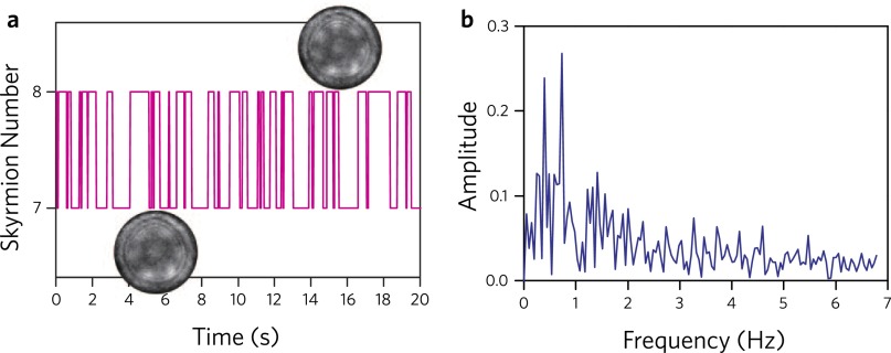
Besides the aforementioned properties of skyrmion cluster states, a more striking feature is that we observed a series of quantized jumps during the transition between the two cluster states at a defined magnetic field H. In other words, there exists a quantization intermittent fluctuation region for the transition from one cluster state to another. For example, Fig. 2M shows a typical Ns(t) versus time t at a fixed H ≈ 0.98 kOe (see Movie S1), where the two cluster states with Ns = 6 and 5 change by the annihilation or creation, alternatively, of the skyrmion at the center of the disk, and such two-level jumps can survive in the wide range from 0.56 kOe to 1.01 kOe (Fig. 2 E–G). This phenomenon is widely observed during the field-driven transition of the cluster states (see Fig. S2 and Movies S1–S5) at temperatures close to Tc, as shown in Fig. 2N, where the intermittent jumps of cluster states with Ns = 2 and 1 were clearly seen at H ≈ 1.41 kOe. A frequency spectrum of the jumped behavior by Fourier analysis is shown in Fig. S3, exhibiting no notable regularities within the time resolution limit of the Lorentz TEM. The observations and analysis indicate that the system exhibits the telegraph noise, which occurs due to the thermal fluctuation at the first-order transition between cluster states with different skyrmion numbers.
Fig. S2.
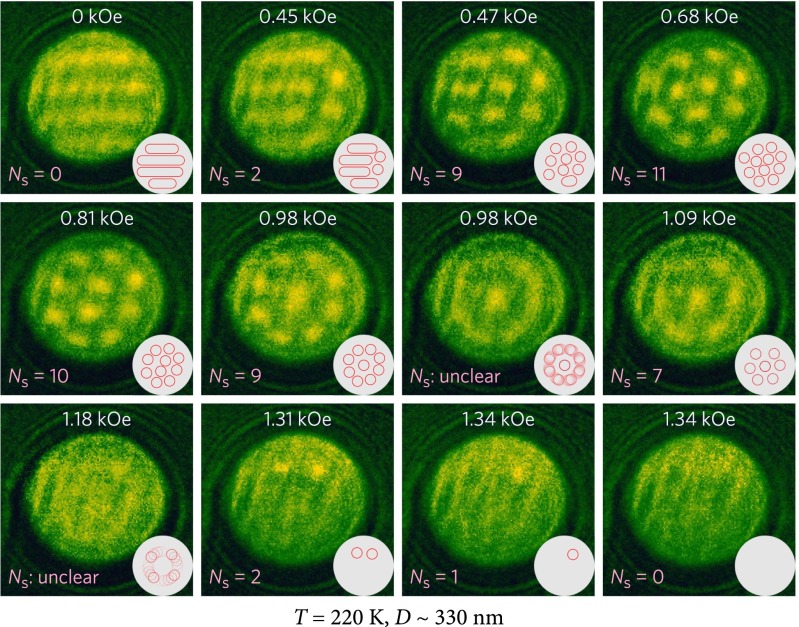
Underfocused Lorentz TEM images of a 330-nm FeGe nanodisk at 220 K under an external magnetic field. At zero field, the ground state consists of four helical periods. With the increase of the external field, some skyrmions were nucleated from the helix at 0.45 kOe, and the skyrmions eventually occupied the whole disk at 0.47 kOe. After the number of skyrmions Ns reaches the maximum of 11, i.e., eight skyrmions circle around the edge of the disk, with three inside the circle. Further increasing the external field, the number of the inner skyrmions, in turn, merges to 2 at 0.81 kOe and 1 at 0.98 kOe. It’s worth noting that, at 0.98 kOe, the eight circumambient skyrmions begin to rotate around the center one, leading to a ring-like structure (see Movie S3). Red circles in the white plate at the corner of each panel point out the position of skyrmions and helixes. All images are extracted from a video captured at a defocus value of −288 μm and an exposure time of 0.2 s.
Fig. S3.
Fourier analysis of the telegraph noise. (A) Skyrmion number in a 330-nm nanodisk jumps between 8 and 7 at a fixed magnetic field H = 0.98 kOe and temperature T = 260 K. (Inset) Images from Lorentz TEM show the configurations of the skyrmion cluster. (B) The amplitude spectrum of A, which exhibits no recognizable regularities. It is worth pointing out that this spectrum is not very accurate, because of the experiment timescale and insufficient time resolution of Lorentz TEM.
Aside from the telegraph noise, for an Ns = 4 cluster with a square symmetry, four skyrmions appear to change their positions with a clockwise or anticlockwise rotation so that the Lorentz TEM images become blurred, with less visible contrast. Such rotational motion is more apparent in the 330-nm disk (see Movie S3 and Fig. S2), where the eight skyrmions circling the disk rotate around the central one or two skyrmions. Unfortunately, the time resolution of Lorentz TEM cannot grasp the detail of skyrmion dynamics in the cluster states, which is highly reminiscent of the thermally driven ratchet motion, as observed in other B20 compounds, including MnSi and Cu2OSeO3 (24). The phase diagram in the H space is illustrated in Fig. 2O. Unlike the tiny magnetic field intervals for states at T = 100 K, elevated temperature brings dramatic thermal fluctuations, overwhelming the magnetization dynamics. Thus, the magnetic field intervals for all of the cluster states are comparable.
Temperature−Field Phase Diagram for the Nanodisk.
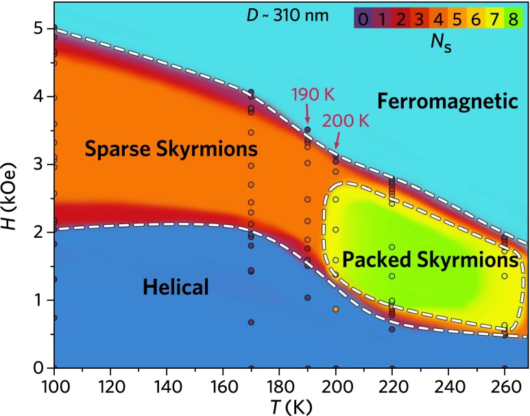
We have also investigated the H-driven spin texture in the whole temperature region from 100 K to 260 K; a typical temperature−field (T-H) phase diagram for a 310-nm nanodisk is shown in the Fig. 3. At the temperature below 190 K, where skyrmions are in sparse distribution forms of cluster state, the maximum number of skyrmions, , is almost unchanged (see Fig. S4). Conversely, closely packed skyrmions appear at T > 190 K. With the current experimental accuracy of temperature control, we don’t catch a crossover region in which the skyrmion number varies from sparse cluster state at low temperatures to closed packed cluster state at high temperatures. This observation possibly indicates that the crossover temperature region might be very narrow or that the transition happens instantly, which needs to be clarified in future work.
Fig. 3.
H-T phase diagram of 310-nm FeGe nanodisk. At temperatures lower than 190 K, skyrmion numbers reached a maximum of 4 in the form of sparse skyrmion. At T above 200 K, skyrmion numbers reached a maximum of 7 or 8 in the form of packed skyrmions.
Fig. S4.
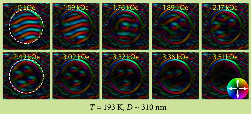
Variations of spin texture with external magnetic field in a 310-nm FeGe nanodisk in the crossover temperature region. At H = 1.76 kOe, skyrmions nucleated from the helix as in the high-temperature region. Meanwhile, the maximal skyrmion number only reached 4, which is less than the number 8 found in higher temperatures.
Relation Between the Maximal Skyrmion Number and the Disk Diameter.
To thoroughly understand the magnetic properties in the confined geometry, we systematically investigated the dependence of skyrmion arrangements on the disk size at two typical temperatures, 100 K and 220 K (the sample parameters are shown in Table S1).
Table S1.
Surface lattice plane, thickness (t), and diameter (D) of the FeGe nanodisks
| Samples | Surface lattice plane | t, nm | D, nm |
| ND1 | (123) | 62 | 310 |
| ND2 | (123) | 65 | 230 |
| ND3 | (123) | 64 | 180 |
| ND4 | (112) | 123 | 410 |
| ND5 | (112) | 126 | 330 |
| ND6 | (112) | 125 | 270 |
| ND7 | (123) | 123 | 240 |
Crystal orientation of samples was determined by selected area electron diffraction, thickness was measured by EELS, and disk diameter was measured from raw Lorentz TEM micrographs.
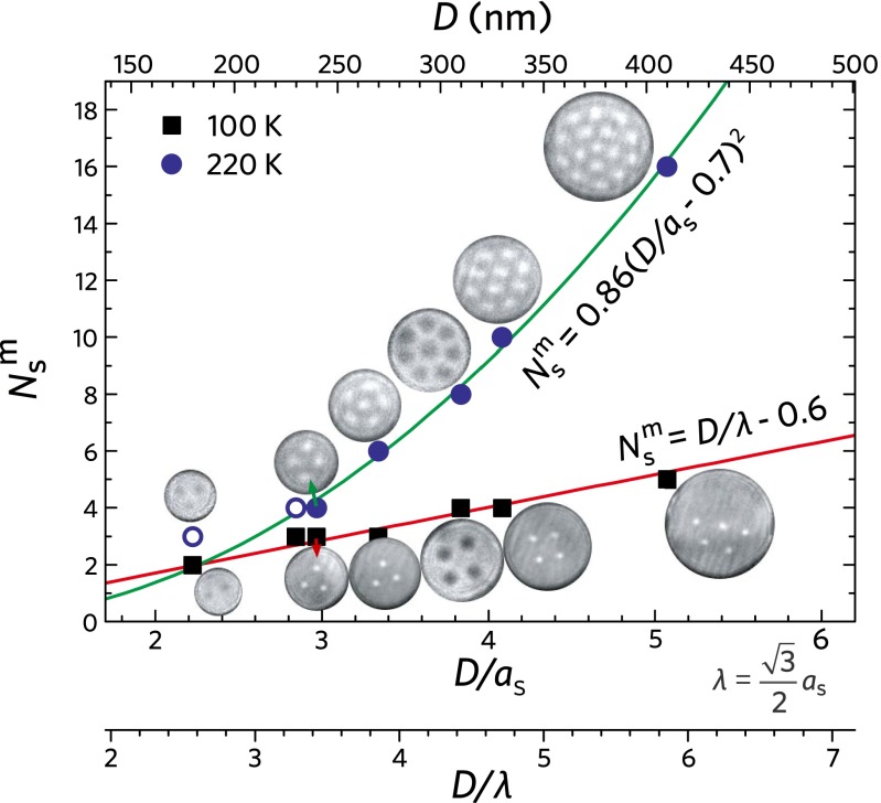
At high temperature, 220 K, a close packing of skyrmions in the skyrmion state is expected. Following the same magnetization dynamics for a 270-nm disk (Fig. S2), we clearly observe the prediction that the maximal number of skyrmions, , increases with the increase of the disk diameter, D (Fig. 4, filled and open blue circles, T = 220 K). However, the variation of with D is discrete due to the particle property of skyrmions. In this case, the arrangement of skyrmions in the disk resembles the packing of congruent circles in a circular container; that is, with the raising of container size, the arrangement of circles varies in the pattern sequence of triangular, square, regular pentagon, five around one, six around one, etc. (SI Maximal Number of Skyrmions and Closest Packing in a Circle and Fig. S5). Considering the fact that the maximum circle number is generally proportional to the area of the container, the variation of the circle number N with container diameter D can be approximately fitted by a phenomenological curve in the form of n = k (D/d – q)2, where k is the packing density constant, D and d are the diameter of the container and small circles, respectively, and constant q comes from the drop of packing density near the circumference of the container. For dense packing, it provides k = 0.861 and q = 0.32 (SI Maximal Number of Skyrmions and Closest Packing in a Circle). Because a small disk may deviate significantly from this rule, the experimental data at larger size D > 240 nm are fitted. We obtained k = 0.86 ± 0.06, q = 0.7 ± 0.1, assuming that d is equal to the featured skyrmion lattice constant ≈ 81 nm; q ≈ 0.7 is larger than that of dense packing situation, which can be interpreted as the presence of edge state, and the deviation of 0.38 implies the size of the edge vortex is on the order of (0.38 as/2) ≈ 15 nm (8, 13), which is also a reasonable estimation.
Fig. 4.
The maximal number of skyrmions as a function of disk size at two representative temperatures, 100 K and 220 K. The bright or dark spots represent skyrmions obtained by direct Lorentz TEM imaging. The difference of bright−dark contrast is due to the magnetic chirality inversion of the skyrmions in different crystal chirality. The open blue circles represents the data that are not be used in the fitting parameters at T ≈ 100 K. The curves show square and linear relationships at high temperature and low temperature, respectively, reflecting two different mechanisms to create skyrmions in confined geometry.
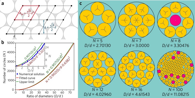
Fig. S5.
(A) Schematic of a hexagonal closest arrangement in a plane. (B) Parabola fitting of the numerical solutions of packing equal circles in a circle. (Inset) Graph showing the fitting of the first 100 rows. With D/d increasing, the fitting curve is apparently getting closer to the upper limit, which is the infinite large plane situation. (C) Some examples of these solutions. The circles in magenta have at least one degree of freedom.
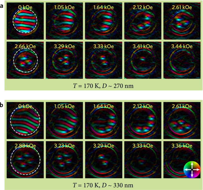
At low temperatures below 190 K, the evolution of the distorted helical state followed the process for a 270-nm disk at T = 100 K, where one complete distorted spin helix changes into one skyrmion (Fig. S6). Because the helical state possesses a relatively fixed period λ, the maximal skyrmion number, , is directly proportional to the reduced size D/λ (Fig. 4, black dots, T = 100 K), i.e., linearly dependent on D. The yielded compensated constant 0.6 indicates the size of the edge vortex is on the order of (0.6 λ/2) = 21 nm, which implies that the region of the edge vortex at low temperatures is larger than that at high temperature.
Fig. S6.
Spin texture evolution with magnetic field at 170 K in FeGe nanodisk with a diameter of 270 nm (A) and 330 nm (B). Helical spin texture gradually evolves to skyrmions with the increase of external magnetic field. The three (or four) skyrmions in the 270-nm (or 330-nm) nanodisk that were nucleated from the edge shift to the center of the disk with further increasing of H. The skyrmion number appears to be equal to that of the helix period. Skyrmions annihilated one by one under increasing magnetic field from 3.29 kOe to 3.44 kOe. The white dashed circles indicate the interface of FeGe and amorphous PtCx, and the color wheel in the last panel indicates the direction and strength of magnetization.
Discussion
Since the discovery of magnetic skyrmion in 2009, quite a few theoretical and experimental works have been performed on the spin textures and magnetization process in confined helimagnets including nanodisks, nanowires with circular or parallelogram cross-sections (8, 13, 15); the elemental results lie in the emergent skyrmion cluster states and discrete transitions between them due to the confined geometry. These predictions were directly confirmed by our Lorentz TEM study. Meanwhile, several previously unidentified properties were found beyond the conventional predictions. For example, the magnetic field intervals for these different cluster states depend on the temperature, and show remarkable deviation from the theoretical results (8, 13). In addition, the temperature effect is not fully considered theoretically, so the telegraph noise is not predicted. Moreover, recent works have successively discovered several skyrmion materials at or above room temperature, including beta-Mn-type CoZnMn alloys (25), CoFeB/Ta bilayers (26), ultrathin Pt/Co/MgO nanostructures (10), and Ir/Co/Pt multilayers (27). These advances unambiguously promote real application. However, the thermal telegraph noise observed in the present work would provide another perspective on these efforts, because thermal fluctuations may impose limits on the development of skyrmion-based devices.
Skyrmions have many features in common with Abrikosov vortices in superconductors (28, 29). They are both condensed into a triangular lattice in bulk or 2D films due to the minimization of their repulsive interactions. It is well established that size confinement would lead to certain novel quantum objects, such as the giant vortex in a superconducting nanodisk, which cannot survive in a macroscopic sample. Similar to the giant vortex, a new topological state, named target skyrmion, characterized by a skyrmionic core with a series of circular spin stripes, has been suggested in nanodisks or nanowires under certain conditions (8, 30). Especially, the target skyrmion may be the spontaneous ground state, as the disk size is close to the featured helical period (31). Similar target domain structure has been observed in Ni and FePt nanodots (32, 33). However, the theory-predicted target skyrmion in the chiral magnets is not observed in the present experiment. We have tried to image the magnetic structure on the disk with a diameter around 100 nm, but the weak magnetic contrast and Fresnel fringe make it impossible to obtain valuable information so far. The search for the target skyrmion is still an interesting issue.
The skyrmion is a particle-like spin configuration with an integer topological charge. Its particle behavior makes it instructive to compare the ordering and dynamics of skyrmion cluster states in confined geometries (34–38) with the broader class of systems exhibiting mesoscale ordering in similar geometries. The observed behavior of magnetic skyrmion clusters in a nanodisk shows a similarity to various other phenomena such as the charge ordering in quantum dots, ion crystals, colloidal ordering in traps (37), and dusty plasmas (35). However, different from these orderings, the skyrmion number is not conserved, and thus the dynamical transitions between the cluster states with different skyrmion numbers is unique.
In conclusion, we have addressed the problem of the quantum skyrmion phase transitions in strongly confined helical magnets, i.e., nanodisks with comparable size to the helical period. All of the disks show a distorted helical ground state. On an external magnetic field aligned perpendicular to the disk plane, the helical ground state split into individual skyrmions, with the maximum number determined by the disk size and temperature. The phase transitions between these cluster states are abrupt, with the appearance of telegraph noise at high temperature. These results reveal unique physics of the skyrmion cluster states in confined geometries, and can guide the development of skyrmion-based memory devices in which the individual skyrmions could be used for multibit memory cells.
Materials and Methods
Sample Fabrication.
The B20-type FeGe samples were synthesized with a cubic anvil-type high-pressure apparatus with the detailed description in ref. 15. The nanodisks for TEM observation were prepared by using an FIB and scanning electron microscope (SEM) dual beam system (Helios Nanolab 600i; FEI) combined with a gas injection system (GIS), and a micromanipulator (Omniprobe 200+; Oxford Instruments). The details of the sample fabrication processes are shown in Fig. S1. The parameters of fabricated samples with varied diameters are summarized in Table S1.
Lorentz TEM Measurements.
The high-resolution lateral magnetization distribution map was obtained by TIE analyses of the Lorentz TEM images. Thin-plate thickness was measured using electron energy loss spectroscopy (EELS). A double-tilt liquid-nitrogen cooling holder (Cryo-Transfer Holder; Gatan) was used to detect the phase transition below the Curie transition temperature Tc. This enables the specimen temperature to be reduced to 100 K, with the measured temperature displayed on the cooling holder controller. The magnetic field applied normal to the thin plate was induced by the magnetic objective lens of the TEM (JEM2100F; JEOL).
SI Maximal Number of Skyrmions and Closest Packing in a Circle
If we consider the maximal number of skyrmions () in a nanodisk at a temperature near Tc, assuming that a skyrmion is incompressible and the number of skyrmions is inclined to be as large as possible, we will encounter the geometry problem of closest packing of equal circles in a circle. This problem can be split into two stages.
Closest Packing of Equal Circles in an Infinite Circle.
The closest packing of circles in an infinite plane is known as hexagonal packing, which can be extracted to a lattice composed of rhombuses (Fig. S5A). If the lattice constant is d, the line spacing λ would be , and the area of a unit cell Asc would be . Hence, the number of circles in a large circle would be (Fig. S5B), in which D stands for the diameter of the circular container.
Closest Packing of Equal Circles in a Finite Circle.
E. Specht (hydra.nat.uni-magdeburg.de/packing/cci/) made a list of the best-known results of packing of equal circles in a circle (39) with N up to 5,000, most of which, especially for large N, are numerical solutions. The first 100 rows of the list can be fitted in a parabola as (Fig. S5B, Inset), and the whole list can be fitted as (Fig. S5B). As N increases, the proportion of the hexagonal arrangement rises, which brings the coefficient toward an upper limit of 0.907.
Supplementary Material
Acknowledgments
The authors thank Runwei Li, Xianhui Chen, and Changjing Jin for assistance with the sample fabrications. This work was supported by the Ministry of Science and Technology of China (973 Program 2013CB932901), National Natural Science Foundation of China (11274066, 11474290, 51172047, 51102050, 11374302, U1432251, and U1330118), Youth Innovation Promotion Association CAS 2015267, the program of Users with Excellence sponsored by the Hefei Science Center of CAS, and the CAS/SAFEA international partnership program for creative research teams of China. This project was sponsored by Shanghai Pujiang Program and “Shu Guang” project of Shanghai Municipal Education Commission and Shanghai Education Development Foundation (09SG01).
Footnotes
The authors declare no conflict of interest.
This article is a PNAS Direct Submission.
This article contains supporting information online at www.pnas.org/lookup/suppl/doi:10.1073/pnas.1600197113/-/DCSupplemental.
References
- 1.Nagaosa N, Tokura Y. Topological properties and dynamics of magnetic skyrmions. Nat Nanotechnol. 2013;8(12):899–911. doi: 10.1038/nnano.2013.243. [DOI] [PubMed] [Google Scholar]
- 2.Neubauer A, et al. Topological Hall effect in the A phase of MnSi. Phys Rev Lett. 2009;102(18):186602. doi: 10.1103/PhysRevLett.102.186602. [DOI] [PubMed] [Google Scholar]
- 3.Jonietz F, et al. Spin transfer torques in MnSi at ultralow current densities. Science. 2010;330(6011):1648–1651. doi: 10.1126/science.1195709. [DOI] [PubMed] [Google Scholar]
- 4.Zhang X, et al. Skyrmion-skyrmion and skyrmion-edge repulsions in skyrmion-based racetrack memory. Sci Rep. 2015;5:7643. doi: 10.1038/srep07643. [DOI] [PMC free article] [PubMed] [Google Scholar]
- 5.Iwasaki J, Mochizuki M, Nagaosa N. Current-induced skyrmion dynamics in constricted geometries. Nat Nanotechnol. 2013;8(10):742–747. doi: 10.1038/nnano.2013.176. [DOI] [PubMed] [Google Scholar]
- 6.Sampaio J, Cros V, Rohart S, Thiaville A, Fert A. Nucleation, stability and current-induced motion of isolated magnetic skyrmions in nanostructures. Nat Nanotechnol. 2013;8(11):839–844. doi: 10.1038/nnano.2013.210. [DOI] [PubMed] [Google Scholar]
- 7.Lin SZ, Reichhardt C, Saxena A. Manipulation of skyrmions in nanodisks with a current pulse and skyrmion rectifier. Appl Phys Lett. 2013;102(22):222405. [Google Scholar]
- 8.Leonov AO, Rößler UK, Mostovoy M. Target-skyrmions and skyrmion clusters in nanowires of chiral magnets. EPJ Web Conf. 2014;75:05002. [Google Scholar]
- 9.Buettner F, et al. Dynamics and inertia of skyrmionic spin structures. Nat Phys. 2015;11(3):225–228. [Google Scholar]
- 10.Boulle O, et al. Room-temperature chiral magnetic skyrmions in ultrathin magnetic nanostructures. Nat Nanotechnol. 2016 doi: 10.1038/nnano.2015.315. [DOI] [PubMed] [Google Scholar]
- 11.Shinjo T, Okuno T, Hassdorf R, Shigeto K, Ono T. Magnetic vortex core observation in circular dots of permalloy. Science. 2000;289(5481):930–932. doi: 10.1126/science.289.5481.930. [DOI] [PubMed] [Google Scholar]
- 12.Roessler UK, Leonov AA, Bogdanov AN. Chiral skyrmionic matter in non-centrosymmetric magnets. J Phys Conf Ser. 2011;303:012105. [Google Scholar]
- 13.Du H, Ning W, Tian M, Zhang Y. Field-driven evolution of chiral spin textures in a thin helimagnet nanodisk. Phys Rev B. 2013;87(1):014401. [Google Scholar]
- 14.Milde P, et al. Unwinding of a skyrmion lattice by magnetic monopoles. Science. 2013;340(6136):1076–1080. doi: 10.1126/science.1234657. [DOI] [PubMed] [Google Scholar]
- 15.Du H, et al. Electrical probing of field-driven cascading quantized transitions of skyrmion cluster states in MnSi nanowires. Nat Commun. 2015;6:7637. doi: 10.1038/ncomms8637. [DOI] [PMC free article] [PubMed] [Google Scholar]
- 16.Leonov AO, et al. 2015. The properties of isolated chiral skyrmions in thin magnetic films. arXiv:1508.02155.
- 17.Du H, et al. Edge-mediated skyrmion chain and its collective dynamics in a confined geometry. Nat Commun. 2015;6:8504. doi: 10.1038/ncomms9504. [DOI] [PMC free article] [PubMed] [Google Scholar]
- 18.Yu XZ, et al. Near room-temperature formation of a skyrmion crystal in thin-films of the helimagnet FeGe. Nat Mater. 2011;10(2):106–109. doi: 10.1038/nmat2916. [DOI] [PubMed] [Google Scholar]
- 19.Yu XZ, et al. Real-space observation of a two-dimensional skyrmion crystal. Nature. 2010;465(7300):901–904. doi: 10.1038/nature09124. [DOI] [PubMed] [Google Scholar]
- 20.Wilson MN, et al. Extended elliptic skyrmion gratings in epitaxial MnSi thin films. Phys Rev B. 2012;86(14):144420. [Google Scholar]
- 21.Wilson MN, et al. Discrete helicoidal states in chiral magnetic thin films. Phys Rev B. 2013;88(21):214420. [Google Scholar]
- 22.Ezawa M. Compact merons and skyrmions in thin chiral magnetic films. Phys Rev B. 2011;83(10):100408. [Google Scholar]
- 23.Oike H, et al. 2015. Topological stability versus thermal agitation in a metastable magnetic skyrmion lattice. arXiv:1506.00363.
- 24.Mochizuki M, et al. Thermally driven ratchet motion of a skyrmion microcrystal and topological magnon Hall effect. Nat Mater. 2014;13(3):241–246. doi: 10.1038/nmat3862. [DOI] [PubMed] [Google Scholar]
- 25.Tokunaga Y, et al. A new class of chiral materials hosting magnetic skyrmions beyond room temperature. Nat Commun. 2015;6:7638. doi: 10.1038/ncomms8638. [DOI] [PMC free article] [PubMed] [Google Scholar]
- 26.Jiang W, et al. Magnetism. Blowing magnetic skyrmion bubbles. Science. 2015;349(6245):283–286. doi: 10.1126/science.aaa1442. [DOI] [PubMed] [Google Scholar]
- 27.Moreau-Luchaire C, et al. Additive interfacial chiral interaction in multilayers for stabilization of small individual skyrmions at room temperature. Nat Nanotechnol. 2016 doi: 10.1038/nnano.2015.313. [DOI] [PubMed] [Google Scholar]
- 28.Grigorieva IV, et al. Direct observation of vortex shells and magic numbers in mesoscopic superconducting disks. Phys Rev Lett. 2006;96(7):077005. doi: 10.1103/PhysRevLett.96.077005. [DOI] [PubMed] [Google Scholar]
- 29.Cren T, Serrier-Garcia L, Debontridder F, Roditchev D. Vortex fusion and giant vortex states in confined superconducting condensates. Phys Rev Lett. 2011;107(9):097202. doi: 10.1103/PhysRevLett.107.097202. [DOI] [PubMed] [Google Scholar]
- 30.Du H, Ning W, Tian M, Zhang Y. Magnetic vortex with skyrmionic core in a thin nanodisk of chiral magnets. EPL. 2013;101(3):37001. [Google Scholar]
- 31.Beg M, et al. Ground state search, hysteretic behaviour, and reversal mechanism of skyrmionic textures in confined helimagnetic nanostructures. Sci Rep. 2015;5:17137. doi: 10.1038/srep17137. [DOI] [PMC free article] [PubMed] [Google Scholar]
- 32.Skidmore GD, Kunz A, Campbell CE, Dahlberg ED. Micromagnetic domain structures in cylindrical nickel dots. Phys Rev B. 2004;70(1):012410. [Google Scholar]
- 33.Moutafis C, et al. Magnetic bubbles in FePt nanodots with perpendicular anisotropy. Phys Rev B. 2007;76(10):104426. [Google Scholar]
- 34.Wineland DJ, Bergquist JC, Itano WM, Bollinger JJ, Manney CH. Atomic ion Coulomb clusters in an ion trap. Phys Rev Lett. 1987;59(26):2935–2938. doi: 10.1103/PhysRevLett.59.2935. [DOI] [PubMed] [Google Scholar]
- 35.Juan WT, Huang ZH, Hsu JW, Lai YJ, Lin I. Observation of dust Coulomb clusters in a plasma trap. Phys Rev E Stat Phys Plasmas Fluids Relat Interdiscip Topics. 1998;58(6):R6947–R6950. [Google Scholar]
- 36.Drocco JA, Reichhardt CJO, Reichhardt C, Jankó B. Structure and melting of two-species charged clusters in a parabolic trap. Phys Rev E Stat Nonlin Soft Matter Phys. 2003;68(6 Pt 1):060401. doi: 10.1103/PhysRevE.68.060401. [DOI] [PubMed] [Google Scholar]
- 37.Bubeck R, Bechinger C, Neser S, Leiderer P. Melting and reentrant freezing of two-dimensional colloidal crystals in confined geometry. Phys Rev Lett. 1999;82(16):3364–3367. [Google Scholar]
- 38.Schweigert IV, IV, Schweigert VA, Peeters FM. Radial-fluctuation-induced stabilization of the ordered state in two-dimensional classical clusters. Phys Rev Lett. 2000;84(19):4381–4384. doi: 10.1103/PhysRevLett.84.4381. [DOI] [PubMed] [Google Scholar]
- 39.Graham RL, Lubachevsky BD, Nurmela KJ, Ostergard PRJ. Dense packings of congruent circles in a circle. Discrete Math. 1998;181(1-3):139–154. [Google Scholar]
- 40.Mayer J, Giannuzzi LA, Kamino T, Michael J. TEM sample preparation and FIB-induced damage. MRS Bull. 2007;32(5):400–407. [Google Scholar]
Associated Data
This section collects any data citations, data availability statements, or supplementary materials included in this article.


