Abstract
Fourier ptychographic microscopy (FPM) is implemented through aperture scanning by an LCOS spatial light modulator at the back focal plane of the objective lens. This FPM configuration enables the capturing of the complex scattered field for a 3D sample both in the transmissive mode and the reflective mode. We further show that by combining with the compressive sensing theory, the reconstructed 2D complex scattered field can be used to recover the 3D sample scattering density. This implementation expands the scope of application for FPM and can be beneficial for areas such as tissue imaging and wafer inspection.
OCIS codes: (180.0180) Microscopy, (090.1995) Digital holography, (110.6880) Three-dimensional image acquisition
1. Introduction
Fourier Ptychography (FP) [1,2] is a recently developed phase retrieval technique that utilizes intensity images of limited numerical aperture (NA) overlapped in the Fourier domain to reconstruct a sample’s complex field. In the original demonstration [1], angularly varying illumination realized by an LED matrix is used to scan the sample’s Fourier spectrum, resulting in an expanded synthesized NA of the system. Images with resolution higher than the diffraction limit of the objective lens can be reconstructed [1,3]. Quantitative phase measurement of the sample is also achieved [4].
The limitation of the angular illumination configuration of FP is its requirement on a sample’s thickness [3]. Once the sample’s thickness exceeds the thin-sample limit, the simple correlation between the change of illumination angle and the shift in 2D Fourier spectrum is no longer valid, and the phase retrieval algorithm fails. Several improvements of FP are reported to deal with thick samples. Tian et al. [5] proposed and demonstrated a modification on FP to reconstruct a 3D sample by approximating the 3D sample as a stack of 2D slices. Horstmeyer et al. [6] modeled the imaging process as diffraction tomography and modified the reconstruction accordingly, resulting in a phase retrieval of the scattering density of a 3D sample. For both modifications, the computational complexity of FP is increased dramatically.
The thin-sample requirement can be circumvented by implementing FP with an alternate configuration, in which a scannable aperture is placed at the Fourier plane of the imaging system while the sample is illuminated with a single plane wave [7]. In this configuration, the 2D wavefront (light field scattered by the sample’s 3D distribution) exiting the thick sample is modulated by the scannable aperture, captured at the imaging plane, and reconstructed by the conventional FP algorithm. The thin sample requirement is circumvented because the phase retrieval problem is now limited to reconstructing the unchanging 2D wavefront exiting the sample. Moreover, comparing with Tian and Horstmeyer’s modifications, this configuration uses the original reconstruction algorithm and thus has a much lower computational complexity.
In this work, we demonstrate the usage of conventional microscope elements to build an aperture scanning FP microscope (ASFPM) in section 2. This work builds on previous non-microscopy FP work that are focused on 3D sample refocusing [7] and aberration removal [8]. We show that ASFPM extends these works to demonstrate transmissive mode and reflective mode microscopic imaging. In section 3, we image spirogyra (transmissive) and microprocessor chip (reflective) with our setup, and demonstrate our ability to refocus through thick samples at designated plane. In section 4, we show that ASFPM’s reconstructed result could be combined with decompressive recovery method to recover the 3D sample scattering density information.
2. System setup
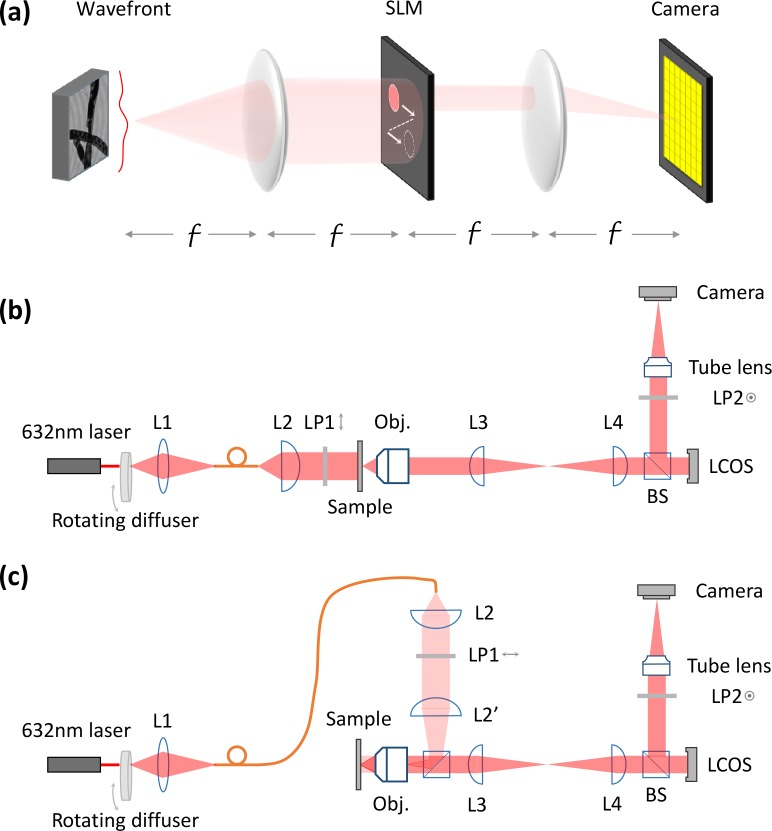
The core of ASFPM is a 4-f imaging system with a spatial light modulator (SLM) at the intermediate Fourier plane, as shown in Fig. 1(a). The wavefront exiting the sample is collected by the first lens, passing through the open aperture of the SLM and reimaged on the camera. A sequence of intensity images of the wavefront is captured with different parts of the SLM aperture opened. The captured images contain different spatial frequency information of the wavefront determined by the open aperture’s location. These images are the input of the phase retrieval algorithm [1] to be stitched in the Fourier domain. The aperture opening sequence is arranged such that the adjacent apertures have a certain degree of overlap [9], providing redundant information for the phase retrieval algorithm to retrieve phase information merely from intensity measurements. The reconstructed complex Fourier spectrum is then converted to the complex sample wavefront, with the resolution limited by the aperture scanning range of the SLM. Because the wavefront carries information from the entire sample volume, it can be further processed to analyze sample distribution at different depths.
Fig. 1.
Principle of aperture scanning Fourier ptychographic microscopy (a), and schematic for transmissive (b) as well as reflective (c) mode microscope system. f: focal length of the lens; L, lens; LP, linear polarizer; Obj., objective lens; BS, beam splitter
The experimental setup of the transmissive mode and reflective mode ASFPM are shown in Fig. 1(b) and (c), in which a reflective mode liquid crystal on silicon display (LCOS display) (Model: Holoeye LC-R 1080) in combination with a pair of linear polarizers (LP1 and LP2) are used as the SLM. An objective lens (Olympus 20X 0.4NA) and a tube lens serve as the forward and inverse Fourier transforming device for the 4f system. Because the back focal plane of the objective lens is inside the lens set and not accessible by the LCOS, a 1:1 relay lens system (L3 with L4) is added in between to image the back focal plane of the objective onto the LCOS. For the illumination, light from a He-Ne laser (λ=632.8nm) is first shined on a rotating ground glass diffuser. The rotating diffuser decreases the temporal coherence of the light, which reduces the speckles in the captured image [10]. The scattered light from the diffuser is then collected into a multi-mode fiber, which allows for easy switching between transmissive and reflective mode. For both modes, lenses are arranged to illuminate the sample with a collimated beam.
While prior work [8] has used an electronically addressable SLM to implement Fourier ptychography, the current setup offers the following 4 key benefits: 1) usage of a reflective LCOS with a much higher fill factor and efficiency than the previously used transmissive liquid crystal display, 2) removal of temporal coherence artifacts, 3) adoption to a microscopic imaging arrangement, and 4) a new capability to operate in a reflective configuration.
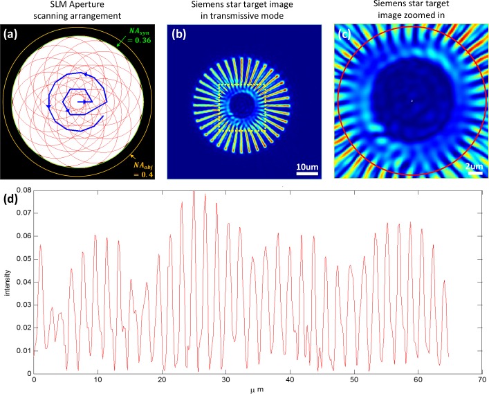
A Siemens star resolution target, recommended by ref. [11], is used as a sample to test the lateral resolution of the imaging system. The patterns are fabricated on gold-coated glass by focused iron beam. For all experiments, a circular aperture on the SLM plane is used to scan the sample’s Fourier spectrum, as shown in Fig. 2(a) by the blue trajectory. Each aperture has 80% of its region overlapped (in one dimension) with its adjacent one, and the scanning covers a Fourier spectrum range equaling a numerical aperture of NAsyn = 0.36, which is within the NA of the 20X 0.4NA objective lens. 20 images are captured in transmissive mode, and the phase retrieval algorithm is used to reconstruct an image. The intensity of the reconstructed image is shown in Fig. 2(b). The center of the image is magnified and shown in Fig. 2(c). A red circle with spoke periodicity of 1.8 μm is drawn in Fig. 2(c), and the intensity distribution on the circle is plotted in Fig. 2(d). As we can see, the spokes with periodicity of 1.8 μm can be resolved by our imaging system, which matches well with the theoretical resolution defined by the synthesized NA: d = λ/(NAsyn) = 1.76μm.
Fig. 2.
(a) The arrangement of aperture scanning sequence on the SLM plane. A circular aperture is scanned following the blue trajectory. The covered area provides a synthesized NA of 0.36, which is within the objective NA of 0.4. (b–c) Siemens star target intensity image in transmissive mode ASFPM. (d)intensity distribution of the red circle in (c), showing a resolution of 1.8 μm which matches the theoretical resolution of the synthesized NA.
3. Imaging performance
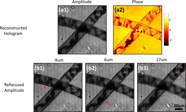
To demonstrate the refocusing capability of ASFPM for a thick sample, a multilayer spirogyra slide is imaged in transmissive mode. The reconstructed hologram is shown in Fig. 3(a1–a2), in which no feature is in focus. The angular spectrum propagation (ASP) method [12] is used to digitally propagate the hologram to distances of −9μm, 6μm, and 17μm away from the objective’s front focal plane as shown in Fig. 3(b1–b3), allowing different segments of the spirogyra to come into focus. The in-focus filament for each refocused plane is indicated by the red arrow, in which the helical arrangement of the chloroplasts can be observed clearly.
Fig. 3.
Transmissive mode ASFPM image of a spirogyra slide. (a1–a2) Amplitude and phase distribution of the reconstructed hologram. (b1–b3) Refocused amplitude image of the hologram at different focal planes, in which different filaments come into focus as indicated by red arrows.
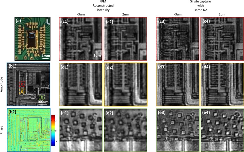
The reflective mode ASFPM can be used to examine non-transparent samples such as semi-conductor devices, metallic structures, and ceramic surfaces. In our experiment, we image a microprocessor (Fig. 4(a)) with our ASFPM and show the reconstructed hologram in Fig. 4(b1–b2). Because the circuit is printed on multiple layers, the hologram needs to be digitally propagated to different planes to bring different regions into focus. As an example, three regions labeled by dashed lines are zoomed in and the intensity images at −3μm and 2μm away respectively from the objective’s focal plane are shown in Fig. 4 (c1–c2, d1–d2, e1–e2). The wires in region c and the top half of the region in d are in focus at 2μm plane, while the grating structure in the bottom half of region d and the structures in region e are in focus at −3μm plane. To verify the result, we display on SLM an open aperture with size equal to the synthesized aperture of ASFPM, and capture two intensity images by physically moving the sample to −3μm and 2μm planes. As shown in Fig. 4(c3–c4, d3–d4, e3–e4), the images match closely with the digitally refocused image generated by ASFPM. Moreover, due to the fact that multiple images are captured and processed in ASFPM, the wire’s features in region c appear smoother and finer than the single capture result. With the digital refocusing capability, researchers can achieve in-focus images of every small part on the microprocessor and also get the information of the height of different layers. These pieces of information are useful for applications such as quality control, reverse engineering and CMOS failure analysis.
Fig. 4.
Reflective mode ASFPM image of a microprocessor chip. (a) Picture of the microprocessor. (b1–b2) Amplitude and phase of the reconstructed hologram. The hologram is digitally propagated to −3μm (c1–e1) and 2μm (c2–e2) away from the objective lens’ focal plane and three sub-regions are zoomed in. Intensity image captured with the aperture opened at NA=0.36 and microprocessor chip physically moved −3μm (c3–e3) and 2μm (c4–e4) are shown as a comparison to the digitally propagated results.
Previous works have verified that the phase information captured in transmissive mode Fourier ptychography, both by angularly-varying-illumination [4] and aperture scanning [8], is quantitative. Here, for the first time, we demonstrate that the phase information captured in reflective mode Fourier ptychography (ASFPM in this case) is quantitative. We spread 10μm microspheres on a silicon wafer, immerse them in mineral oil, and acquire an image with the reflective mode ASFPM. The reconstructed hologram is shown in Fig. 5(a–b). A line trace of phase distribution through one of the microspheres is measured, and converted to microsphere thickness using the equation: Δ = θ/2 * λ/(2π * (noil − nbead)), where θ is the relative phase against background, λ is the wavelength of the laser light, noil = 1.5825 and nbead = 1.5875 are the refractive indices of the mineral oil and the microspheres, respectively. The factor of 2 in the denominator takes into account the fact that the collimated beam passes through the microsphere twice before it is collected by the objective lens. The measurement is plotted in Fig. 5(c) with a blue line, and the theoretical value is shown with a black line for comparison. The close agreement between the measured and theoretical line plots proves that the phase information we reconstruct from ASFPM is quantitative.
Fig. 5.
ASFPM image of 10μm microspheres on silicon wafer, immersed in mineral oil. Reconstructed amplitude (a) and phase (b) distribution of the hologram. (c) The phase distribution through the dashed line in (b) is converted to the microsphere’s thickness and plotted with a blue line. The theoretical thickness distribution is plot with a black line, showing a good match with the measurement.
4. Decompressive inference of hologram
As mentioned in section 2, ASFPM captures the complex wavefront distribution at the focal plane of the objective lens. When the sample is thin and in focus, the complex wavefront represents the amplitude and phase distribution of the sample. When the sample is thick, this wavefront carries the 3D information of the sample and can be used to bring into focus different planes of interest, as demonstrated in Fig. 3 and 4.
Furthermore, with the combination of compressive sensing theory [13–15], here we show that 3D tomographic structure of the sample can be recovered from a single frame of 2D holographic data. Similar work and analysis were carried out by Brady et al. [16], in which they used Gabor holography, but only recorded the intensity of the 2D holographic data. Because of the loss of phase information, a few approximations had to be made and the method had difficulties dealing with a phase target. In our case, ASFPM records both the amplitude and phase information of the hologram. We show in the following section that the quantitative phase as well as the amplitude information of a sample can be recovered from the decompressive inference.
4.1. Forward model of the compressive sampling process
When a 3D sample with the scattering density of η(x′, y′, z′) is illuminated with a monochromatic plane wave, the scattered field E(x, y) is defined under the Born approximation [17] as:
| (1) |
where h is the point spread function which can be calculated as the product of exp(ik0z) (the phase delay at a distance z) [18] and the inverse Fourier transform of the propagation transfer function [12], and k0 = 2π/λ is the wavevector.
We place the front surface of the 3D sample with scattering density η(x′, y′, z′) at the focal plane of the imaging system, i.e. z′ = 0. To discretize the equation, we let: 1) lateral sample spacings be Δx = Δy = Δ; 2) axial sample spacing be Δz; and 3) number of pixels along each dimension of the sample be N. Using this notation, the relationship between the discretized 2D scattered field distribution En1n2 = E(n1Δ, n2Δ) and the discretized 3D sample scattering density can be expressed as [16] :
| (2) |
This equation can be further simplified by noticing the following two facts: 1) the terms in the square bracket represent the 2D discrete Fourier transform of ; 2) the last exponential term in the last line of Eq. (2) forms the inverse 2D Fourier transform in conjunction with the summations over m1 and m2. Hence, Eq. (2) can be interpreted as [16]:
| (3) |
where η̂ denotes the Fourier transform of η, and denotes the 2D inverse Fourier transform operation on subscript m1 and m2. In this interpretation, the 3D sample is treated as a stack of 2D slices, and the 2D scattered field En1n2 is the summation of slice-wise scattered field.
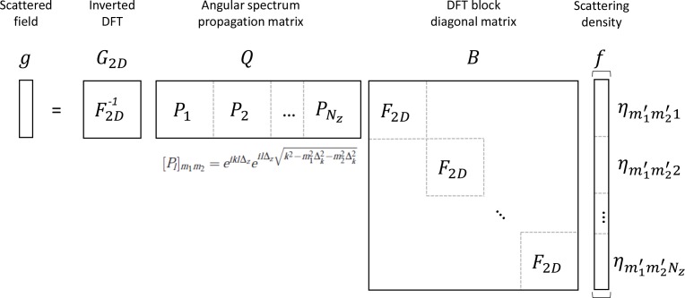
To write the equation into a matrix form for the purpose of decompressive inference, we need to reshape the 2D scattered field En1,n2 and 3D sample scattering density into 1D vectors g ∈ ℂNxNy×1 and f ∈ ℂNxNyNz×1 respectively. We define g(n2−1) × Nx+n1 = En1,n2, and , where Nx, Ny and Nz denote the number of pixels in the x-direction, y-direction and z-direction, respectively.
The operation can also be written in matrix form by defining 1) B = blkdiag(F2D, F2D, ..., F2D) with F2D being the matrix representing the 2D DFT whose size is (Nx Nz) × (Ny Nz), and “blkdiag” denoting the block diagonal matrix; 2) Q = [P1P2...PNz] with , where [Pl]m1m2 represents the element of the matrix Pl at the intersection of the row m1 and the column m2; and 3) G2D represents the 2D inverse DFT matrix.
With these definitions, Eq. (3) can be rewritten as:
| (4) |
Figure 6 shows the matrix representation of the compressive sampling forward model in the above discussion. The ‘compressing’ process is the process in which all the slices of the 3D sample propagate and project on to a 2D focal plane, where the complex hologram is captured. In matrix form, the ‘compressing’ process is incorporated in the matrix Q, in which the slice-wise information is summed up and shrunk in size.
Fig. 6.
Matrix representation of the compressive sampling model
The linear relationship between the detected hologram and the sample scattering density is the key to decompressive inference. In comparison, for Ref. [16] to achieve a similar linear relationship, the technique had to capture hologram at a significant distance from the sample of interest and exclude the nonlinear term caused by intensity-only measurement. These approximations added to the error of their system and resulted in an inaccurate phase recovery.
4.2. Decompressive inference using total variation constraint
To simplify the discussion, let H = G2DQB represent the operation of hologram acquisition. In ref. [16], Brady et al. showed that this holographic acquisition matrix H obeys the restricted isometry property (RIP) [13,14] as a compressive multiplexed encoder, which ensures an accurate recovery of f from the compressive measurement of g = Hf with a high probability. We note here that in this previous case, the hologram acquisition process only determined the real values of the optical field, whereas in our case the acquired field can take on any complex value at each pixel. As a result, our matrix can map values to the entire complex space, as opposed to just the real axis. Thus, our matrix H obeys the RIP of higher order [19] and can in principle lead to the successful reconstruction of samples that are less sparse.
There are different approaches to recover f, such as selecting a basis (wavelets, for instance) in which f may be assumed to be sparse, or enforcing a sparsity constraint on the total variation (TV), as defined by Rudin et al. [20], of f. In this work, we select the second method and model the decompressive recovery of f as an optimization problem:
| (5) |
where ‖f‖TV is defined by
| (6) |
where fl denotes a 2D slice of the 3D object datacube. This optimization problem can be solved using the two-step iterative shrinkage/thresholding algorithm (TwIST) proposed in ref. [21]. In this work, we adapt the released MATLAB code from Bioucas-Dias et al. [22] to inversely recover f from our measurement of g, which is the complex hologram reconstructed from ASFPM.
4.3. Experimental results
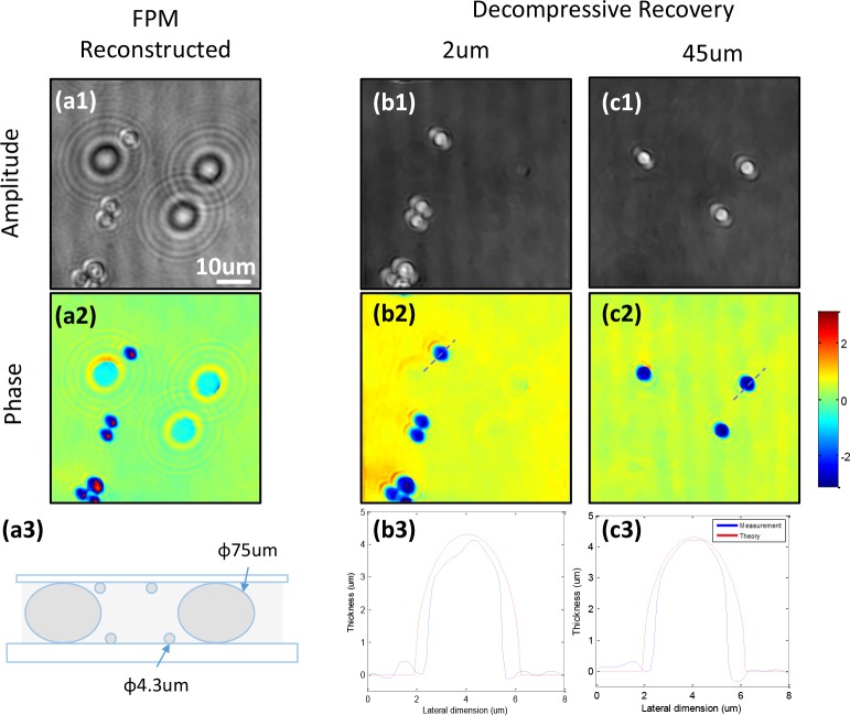
To experimentally demonstrate the performance of decompressive recovery, a two-layer microsphere sample is prepared. A mixture of microspheres with diameter of 4.3 μm (target) and 75 μm (spacer) is spread on the surface of a microscope glass slide and a #1.5 coverslip. These two surface are glued together (face to face) with the immersion oil in between, as shown in Fig. 7(a3). The sample is imaged with the ASFPM setup and the amplitude and phase image is shown in Fig. 7(a1–a2). As we can see, the microspheres that are on the glass slide are close to the in-focus plane, while the microspheres that are on the coverslip are defocused and casting large diffraction rings on top of the image. The hologram is digitally refocused to different imaging planes using ASP, and we find the two planes corresponding to the in-focal plane of the two layers are at 2μm and 45μm (the gap is not 75μm because the spacer microspheres are squeezed in the gluing process). The holographic acquisition matrix H is constructed according to these parameters, and the modified TwIST algorithm is used to recover the sample scattering density on these two planes from the complex hologram reconstructed using ASFPM.
Fig. 7.
Decompressive recovery of a microsphere sample. (a1–a2) Reconstructed amplitude and phase information of the sample using ASFPM. (a3) Two-layer sample configuration. (b–c) Amplitude and phase from decompressive recovery at (b1–b2) 2μm and (c1–c2) 45μm focal planes. (b3) and (c3) are the thickness profiles of microsphere calculated from the recovered phase through the two lines in (b2) and (c2), shown in blue. The red lines show the theoretical thickness value of the 4.3μm microsphere.
The recovered amplitude and phase distribution of the two layers are shown in Fig. 7(b1–b2, c1–c2). As we can see, the sample information in these two planes are mostly isolated, and the large diffraction fringes disappear. To verify the quantitative-phase-recovery capability of this method, line traces through the center of two microspheres, one in 2μm plane and the other in 45μm plane are used to calculate the corresponding thickness (same method as mentioned in section 3) and are shown in Fig. 7(b3, c3) with blue lines. The theoretical thickness profile are shown with red lines, which match the recovered result well.
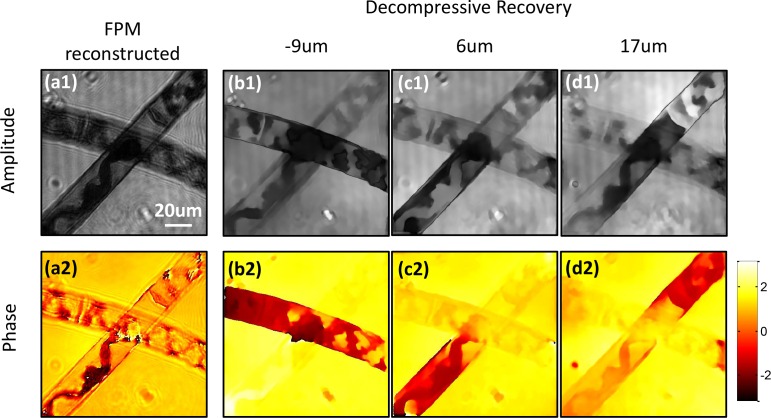
In the second experiment, the spirogyra image shown in Fig. 3 is inputted into the decompressive recovery algorithm. In this case, the algorithm is modified to recover the sample information in three planes: −9μm, 6 μm and 17 μm, which are the planes with the sharpest features when refocused. The recovery results are shown in Fig. 8. The in-focus parts of the sample manifest themselves in the corresponding planes, both for the amplitude and phase images. The chloroplasts in the three planes are also reconstructed clearly.
Fig. 8.
Decompressive recovery of spirogyra sample from Fig. 3. (a1–a2) Amplitude and phase reconstructed from ASFPM. (b1–d1) Amplitude and (b2–d2) phase recovered from decompressive recovery at −9μm, 6 μm and 17 μm plane.
We would like to point out that the recovered result has worse resolution compared to the ASP result. There are two reasons causing this: 1) The spirogyra sample is continuously distributed in z direction, thus the effort to isolate the 3D continuous information into three slices of 2D distribution introduces some error. 2) The sample is a complicated bio-structure which is not sparse enough in terms of total variation, where the TwIST algorithm used to recover the solution to Eq. (5) finds a sparse version of the real sample distribution [23]. The solution has a lower resolution because a smoother function has a smaller total variation compared to a high resolution function with more fine features. The decompressive recovery process may be improved by 1) adding more slices in the reconstruction, and 2) implementing sophisticated sparsity constraint such as dictionary learning [24].
We also point out that implementing decompressive recovery is optional in the imaging process of ASFPM. This implementation extracts 3D sample information from the 2D reconstructed complex sample field at the cost of a much longer additional computational time. Whether or not to implement decompressive recovery will depend on the imaging requirement and the computational budget.
5. Conclusion
In summary, we implemented an aperture-scanning-based Fourier ptychographic microscopy system which reconstructs the complex wavefront from a sequence of intensity measurements. Compared with the angularly varying illumination configuration of FP, this configuration has a few advantages: 1) due to the unchanging scattered field originating from the sample in this scheme, the thin-sample requirement of angularly varying illumination FP is circumvented and the complex wavefront can be reconstructed by the conventional FP algorithm without additional computational cost; 2) by imposing a smaller sized aperture at the pupil plane of the objective lens, ‘pixel super-resolution’ [7] can be realized. In other words, a larger-pixel-size imaging sensor (CCD or CMOS) with sampling spatial frequency below the Nyquist frequency of the objective lens could be used in the imaging system. This may bring down the cost of the imaging system, or provide images with better noise performance; 3) without the requirement of angularly varying illumination, FP can be implemented on applications in which the space between sample and imaging system is not easily accessible, such as wafer inspection and retinal imaging.
In this reported work, aperture scanning is implemented by relaying the objective pupil plane onto an LCOS spatial light modulator. Comparing to the previously reported system [7] which uses a mechanically scanning aperture, this aperture scanning scheme can provide faster and more precise scanning, and more reliable performance over time. Moreover, for the first time to our knowledge, we demonstrate a microscopic aperture-scanning-based Fourier ptychographic imaging system. Also, for the first time, we demonstrated a reflective mode aperture-scanning-based Fourier ptychographic imaging system. We demonstrated applications in imaging thick biological samples (transmissive mode) and microprocessor surfaces (reflective mode) and digital refocusing, and we verified the phase we measure is quantitative. Comparing to other wavefront measurement methods such as digital in line holography [25], ASFPM has several advantages: no interference measurement is needed to reconstruct the phase information, it is easier to align the optical system, and it has a low requirement of temporal coherence which results in much less speckle noise in the reconstructed image.
By the introduction of compressive sensing theory in section 4, we showed that the 3D sample distribution can be recovered from the 2D complex wavefront measurement. To the best of our knowledge, this is the first experimental demonstration of decompressive recovery on measured complex wavefronts. This demonstration shows a broader range of application for ASFPM. Also, we believe that this demonstration can serve as a reference for other wavefront measurement techniques to which decompressive recovery can be adapted to expand their applications.
Acknowledgments
The authors thank Haojiang Zhou and Hangwen Lu for discussions and help with experiments. The authors acknowledge funding support from FLUOROFM (grant no. R01 AI096226) and CII 2015 (grant no. 32070065).
References and links
- 1.Zheng G., Horstmeyer R., Yang C., “Wide-field, high-resolution Fourier ptychographic microscopy,” Nat. Photonics 7, 739–745 (2013). 10.1038/nphoton.2013.187 [DOI] [PMC free article] [PubMed] [Google Scholar]
- 2.Horstmeyer R., Yang C., “A phase space model of Fourier ptychographic microscopy,” Opt. Express 22, 338–358 (2014). 10.1364/OE.22.000338 [DOI] [PMC free article] [PubMed] [Google Scholar]
- 3.Ou X., Horstmeyer R., Zheng G., Yang C., “High numerical aperture Fourier ptychography: principle, implementation and characterization,” Opt. Express 23, 3472–3491 (2015). 10.1364/OE.23.003472 [DOI] [PMC free article] [PubMed] [Google Scholar]
- 4.Ou X., Horstmeyer R., Yang C., Zheng G., “Quantitative phase imaging via Fourier ptychographic microscopy,” Opt. Lett. 38, 4845–4848 (2013). 10.1364/OL.38.004845 [DOI] [PMC free article] [PubMed] [Google Scholar]
- 5.Tian L., Waller L., “3D intensity and phase imaging from light field measurements in an LED array microscope,” Optica 2, 104–111 (2015). 10.1364/OPTICA.2.000104 [DOI] [Google Scholar]
- 6.Horstmeyer R., Yang C., “Diffraction tomography with Fourier ptychography,” arXiv:1510.08756(2015). [DOI] [PMC free article] [PubMed]
- 7.Dong S., Horstmeyer R., Shiradkar R., Guo K., Ou X., Bian Z., Xin H., Zheng G., “Aperture-scanning Fourier ptychography for 3D refocusing and super-resolution macroscopic imaging,” Opt. Express 22, 13586–13599 (2014). 10.1364/OE.22.013586 [DOI] [PubMed] [Google Scholar]
- 8.Horstmeyer R., Ou X., Chung J., Zheng G., Yang C., “Overlapped Fourier coding for optical aberration removal,” Opt. Express 22, 24062–24080 (2014). 10.1364/OE.22.024062 [DOI] [PMC free article] [PubMed] [Google Scholar]
- 9.Dong S., Bian Z., Shiradkar R., Zheng G., “Sparsely sampled Fourier ptychography,” Opt. Express 22, 5455–5464 (2014). 10.1364/OE.22.005455 [DOI] [PubMed] [Google Scholar]
- 10.Kubota S., Goodman J. W., “Very efficient speckle contrast reduction realized by moving diffuser device,” Appl. Opt. 49, 4385–4391 (2010). 10.1364/AO.49.004385 [DOI] [PubMed] [Google Scholar]
- 11.Horstmeyer R., Heintzmann R., Popescu G., Waller L., Yang C., “Standardizing the resolution claims for coherent microscopy,” Nat. Photonics 10, 68–71 (2016). 10.1038/nphoton.2015.279 [DOI] [Google Scholar]
- 12.Goodman J. W., Introduction to Fourier Optics (Roberts and Company Publishers, 2005), 1st ed. [Google Scholar]
- 13.Candès E. J., Romberg J., Tao T., “Robust uncertainty principles: Exact signal reconstruction from highly incomplete frequency information,” IEEE Trans. Inf. Theory 52, 489–509 (2006). 10.1109/TIT.2005.862083 [DOI] [Google Scholar]
- 14.Candès E. J., Tao T., „ “Near-optimal signal recovery from random projections: Universal encoding strategies?” IEEE Trans. Inf. Theory 52, 5406–5425 (2006). 10.1109/TIT.2006.885507 [DOI] [Google Scholar]
- 15.Donoho D. L., “Compressed sensing,” IEEE Trans. Inf. Theory 52, 1289–1306 (2006). 10.1109/TIT.2006.871582 [DOI] [Google Scholar]
- 16.Brady D. J., Choi K., Marks D. L., Horisaki R., Lim S., “Compressive holography,” Opt. Express 17, 13040–13049 (2009). 10.1364/OE.17.013040 [DOI] [PubMed] [Google Scholar]
- 17.Born M., “Quantenmechanik der stoßvorgänge,” Zeitschrift für Physik 38, 803–827 (1926). 10.1007/BF01397184 [DOI] [Google Scholar]
- 18.Blahut R. E., Theory of Remote Image Formation (Cambridge University Press, 2004). 10.1017/CBO9780511543418 [DOI] [Google Scholar]
- 19.Candes E. J., Tao T., “Decoding by linear programming,” IEEE Trans. Inf. Theory 51, 4203–4215 (2005). 10.1109/TIT.2005.858979 [DOI] [Google Scholar]
- 20.Rudin L. I., Osher S., Fatemi E., “Nonlinear total variation based noise removal algorithms,” Physica D. 60, 259–268 (1992). 10.1016/0167-2789(92)90242-F [DOI] [Google Scholar]
- 21.Bioucas-Dias J. M., Figueiredo M. A., “A new TwIST: two-step iterative shrinkage/thresholding algorithms for image restoration,” IEEE Trans. Image Process. 16, 2992–3004 (2007). 10.1109/TIP.2007.909319 [DOI] [PubMed] [Google Scholar]
- 22.Bioucas-Dias J. M., Figueiredo M. A., “Two-step Iterative Shrinkage/Thresholding Algorithm for Linear Inverse Problems,” http://www.lx.it.pt/bioucas/TwIST/TwIST.htm
- 23.Candes E. J., Romberg J .K., Tao T., “Stable signal recovery from incomplete and inaccurate measurements,” Comm. Pure and Applied Math. 59, 1207–1223 (2006). 10.1002/cpa.20124 [DOI] [Google Scholar]
- 24.Mairal J., Ponce J., Sapiro G., Zisserman A., Bach F. R., “Supervised dictionary learning,” Proc. Adv. Neural Inf. Process. Syst. Conf. pp. 1033–1040 (2009). [Google Scholar]
- 25.Yamaguchi I., Zhang T., “Phase-shifting digital holography,” Opt. Lett. 22, 1268–1270 (1997). 10.1364/OL.22.001268 [DOI] [PubMed] [Google Scholar]


