Abstract
A bioactive two-layer coating consisting of hydroxyapatite (HA) and yttria-stabilized zirconia (YSZ) was investigated on cylindrical polyether ether ketone (PEEK) implants using ion beam assisted deposition (IBAD). Post-deposition heat treatments via variable frequency microwave annealing with and without subsequent autoclaving were used to crystallize the as-deposited amorphous HA layer. Microstructural analysis, performed by TEM and EDS, showed that these methods were capable of crystallizing HA coating on PEEK. The in vivo response to cylindrical PEEK samples with and without coating was studied by implanting uncoated PEEK and coated PEEK implants in the lateral femoral condyle of 18 rabbits. Animals were studied in two groups 9 for observation at 6 or 18 weeks post surgery. MicroCT analysis, histology, and mechanical pull-out tests were performed to determine the effect of the coating on osseointegration. The heat-treated HA/YSZ coatings showed improved implant fixation as well as higher bone regeneration and bone-implant contact area compared to uncoated PEEK. The study offers a novel method to coat PEEK implants with improved osseointegration.
Keywords: Coating, hydroxyapatite, ion beam assisted deposition, polyetheretherketone, osseointegration
1. Introduction
Biomedical implants for orthopedic and dental applications are designed to replace damaged internal tissues with the goal of restoring normal biomechanical activity for the patient. In designing these implants, various engineering materials are employed to match the implant device with the surrounding tissue to achieve successful outcomes, a difficult challenge considering the complexity of biological systems. Stress shielding due to improper mechanical matching, and lack of bone apposition due to interfacial chemical interactions are two major concerns stemming from the implant design. Additional surgical intervention is necessary to address complications caused by these issues [1], increasing overall procedural costs and recovery time for the patient. It is expected that engineered materials that exhibit mechanical and surface chemical properties similar to bone tissue will result in reduced occurrences of revision procedures and improved clinical outcomes.
Polyether ether ketone (PEEK), a thermoplastic polymer, has an elastic modulus that falls between that of cancellous and cortical bone. The reduced mechanical mismatch with bone tissue compared to that of metallic implants can reduce stress shielding and has made PEEK popular in a number of clinical applications [2,3]. The inert chemical structure and high heat resistance of this material makes it suitable for a wide range of sterilization techniques such as ethylene oxide, gamma irradiation or autoclave [4]. PEEK is also radiolucent, facilitating effective observation of peri-implant tissue healing.
However, the bioinert chemical properties of PEEK do not promote bone apposition once implanted [5]. Bioactive calcium phosphate coatings such as hydroxyapatite (Ca10(PO4)6(OH)2), or HA, have been applied to metallic implant surfaces to improve osseointegration with promising results [6-8]. Coating processing techniques often involve high temperatures to produce the desired crystalline phase of HA, which has much lower dissolution rates in vivo than amorphous HA, an important consideration for bioresorbable coatings [9,10]. Despite the heat resistance of PEEK with respect to polymers (Tglass = 150 °C; Tmelt = 350 °C), it is not sufficient to withstand the high temperatures needed to crystallize HA, and can be damaged during coating deposition or heat treatment. This has driven recent research in developing a method for modifying the surface of PEEK to improve bioactivity. Three main categories of PEEK modification have been investigated for bioactivity in the literature: i) Surface physical and chemical treatments such as various plasma exposures [11,12], surface functionalization [13], and sulfonation [14], ii) composite HA/PEEK materials [15,16], and iii) alternative HA coating methods such as spin-coating [17], aerosol deposition [18], cold spraying [19], and radiofrequency magnetron sputtering [20]. HA-coated implants offer strong bioactive potential; however, achieving an adequate bond between a ceramic HA coating and a polymer (PEEK) is not trivial and is an important factor in determining success in implantable applications.
Studies recently reported the deposition of a two-layer bioactive coating on PEEK using an ion beam assisted deposition (IBAD) technique [21]. IBAD has proven to be an effective method to increase coating adhesion due to atomic mixing at the film-substrate interface [22,23]. The coating consists of yttria-stabilized zirconia (YSZ) as a heat protection layer over the PEEK substrate and an HA top layer for improved bioactivity. Subsequent heat treatment via microwave processing followed by autoclaving resulted in crystallization of the HA layer without causing damage to the underlying PEEK. YSZ is used as a thermal barrier coating in high temperature applications and its columnar grain structure helps mediate residual film stresses caused by heat treatment. Recent studies have shown these coatings to exhibit high adhesion strength to PEEK substrates, indicating potential for a robust method for implant surface preparation [24]. In addition, an in vitro study using MC3T3 cells showed promising bone growth on coated samples that underwent post-deposition heat treatments [21]. For the in vivo study described herein, uncoated control PEEK implants were compared with coated implants that underwent subsequent heat treatment in order to determine if the HA/YSZ coating deposited by IBAD could improve the osseointegration of PEEK implants.
2. Materials and Methods
2.1 Implants
2.1.1 Sample preparation
PEEK (PEEK-OPTIMA®, Invibio, Lancashire, UK) rods measuring 5 mm in diameter and 9 mm long were used as the implant substrates for coating deposition. The bulk, extruded rod was machined down to achieve the desired implant diameter and length using a lathe. A 1-mm axial through-hole was drilled while mounted to the lathe to aid in implant placement and fixation onto the IBAD substrate holder. Substrates were ground sequentially against 600 and 800-grit silicon carbide paper (Buehler, Lake Bluff, IL, USA) using an automated grinding technique designed to allow for equal material removal in the radial and axial directions by rotational symmetry. The substrate surfaces were rinsed with deionized water between grinding steps to avoid particle contamination. The cylindrical rods were then submerged and ultrasonically cleaned for 10 minutes in acetone, isopropanol, and deionized water, respectively. The substrates were dried via compressed air and stored in sterile tissue culture plates prior to vacuum deposition.
2.1.2 Surface activation
The PEEK substrate surfaces underwent a brief surface treatment via O2 plasma prior to deposition using a radio-frequency plasma barrel reactor (model PM-600, March Instruments, Concord, CA, USA) for 10 minutes. This method has been described in greater detail in previous studies [20,21]. Substrate rods were then mounted on 1 mm titanium rods before being transferred to the IBAD system vacuum chamber for deposition.
2.1.3 Coating deposition
Deposition of the HA/YSZ coatings was achieved by way of a custom rotational substrate fixture and an IBAD system (Univex 600, Oerlikon Leybold Vacuum, Export, PA, USA). The deposition system is composed of 8-inch HA and YSZ sputtering targets (Plasmaterials, Inc, Livermore, CA, USA) with 16-cm primary and 12-cm secondary ion sources outfitted with argon process gas. A custom substrate fixture developed for cylindrical PEEK substrates fixed on rotating titanium rods was used to ensure even coating during deposition. Adjustable-speed simultaneous rotation was achieved by way of a water-cooled gearbox and an external feed-through stepper motor. The ion source deposition parameters were optimized for film thickness and density. The base vacuum achieved before deposition was approximately 5 × 10⁻⁷ Torr and the deposition pressure varied from 3 × 10⁻⁴ to 5 × 10⁻⁴ Torr depending on primary and secondary ion source parameters. The temperatures near the deposition area were monitored during deposition and maintained below the glass transition temperature of PEEK to avoid damage to the polymer substrate. The deposition chamber was vented to atmospheric conditions between the YSZ and HA layer deposition in order to perform the target exchange.
2.1.4 Post-deposition Heat Treatment
The HA/YSZ coatings on PEEK were processed via two heat treatment methods following deposition: i) microwave processing (AD+MW), and ii) microwave plus autoclave processing (AD+MW+AC). For microwave processing, selective heating of the HA coating layer was achieved with the use of a variable frequency microwave oven (Microcure, Lambda Technologies, Morrisville, NC, USA) in order to aid in crystallization of the HA layer without damaging the PEEK substrate. The microwave treatment conditions were administered in accordance with the methods described in patent US8323722 [25]. Subsequent autoclave processing was applied to the coated implants using a commercial sterilization unit (Prevac Steam Sterilizer, Steris, Mentor, OH, USA). The temperature-programmable autoclave was adjusted to apply a saturated steam cycle of 136°C for 8 hours.
Prior to surgical placement, all implants (coated and uncoated PEEK) were sterilized by ethylene oxide and allowed a three-day de-gassing period to ensure no residuals remained on the surface.
2.2 Coating analysis
2.2.1 Microstructural analysis
A Transmission Electron Microscope (TEM) (2100F, Jeol, Huntington Beach, CA, USA) was used to observe coating microstructure, interfacial zones, and to quantify the layer thickness with the use of image analysis software (ImageJ, National Institutes of Health, Bethesda, MD, USA). High-resolution TEM was used to examine the crystallized regions formed within the HA layer by heat-treatment processes. Samples were prepared using focused ion beam (FIB) milling and lift-out. A thin layer of gold (Au) was sputter-deposited on the surface to protect the sample from excessive damage during ion beam thinning and removal.
2.2.2 Compositional analysis
A Scanning Tunneling Electron Microscope (STEM) (Titan, FEI, Hillsboro, OR, USA) equipped with Energy Dispersive Spectroscopy (EDS) was used to determine the atomic percentage of the elements present in the HA coating layer. This data was then used to quantify the Ca/P ratio and compared to stoichiometric HA present in the sputtering target. Two cross-sectional coating regions, approximately 400 nm × 400 nm in size, were used to determine averages for each sample.
2.3 Animal study
2.3.1 Surgical procedure
This study was used to evaluate HA-coated PEEK implants in 18 skeletally mature male New Zealand White rabbits (3.5-4.5 kg). The following surgical protocol was approved and performed within the guidelines of the local Institutional Animal Care and Use Committee (IACUC) facility; NIH guidelines for the care and use of laboratory animals (NIH Publication #85-23 Rev. 1985) have been observed. The rabbits were randomly allocated to one of two time points for observation after either 6 weeks (N=9 animals) or 18 weeks (N=9 animals). Within each time point, the 9 animals yielded 18 implants (N=6 implants of each of the three candidate surface treatments). The rabbits were weighed and administered glycopyrrolate (0.1mg/kg body weight) subcutaneously to reduce salivation during the procedure. Animals were sedated with xylazine (5 mg/kg IM) and anesthetized with ketamine (35 mg/kg IM). Anesthesia was maintained using inhaled isoflurane (1-3% in oxygen) delivered via facemask. When an adequate state of anesthesia was achieved, an ophthalmic ointment (Lacri-Lube) was placed on the conjunctiva of each eye. A single bolus of antibiotics (cephazolin, 25 mg/kg IV) was given immediately before surgery. Buprenorphine (0.05 mg/kg) was also administered intramuscularly to control perioperative pain. Intravenous fluids (5-10 ml Lactated Ringers Solution) were administered via subcutaneous injection. The animal’s body temperature and oxygen saturation were monitored continuously during surgery. The left and right hind limbs were shaved from the hip joint down to the hock joint and the skin cleaned with povidone-iodine surgical scrub. The knee joint was isolated with sterile surgical drapes.
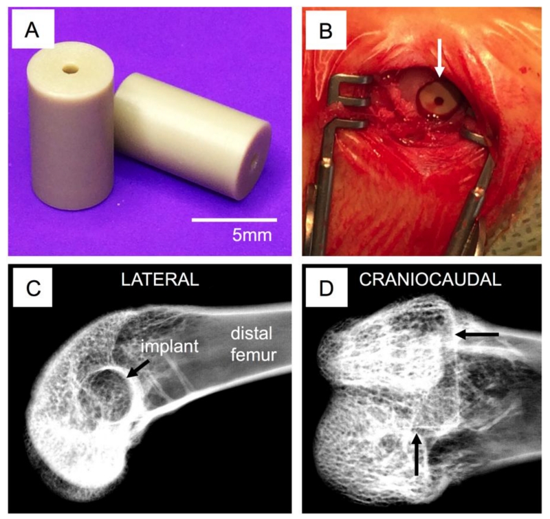
The distal femur was exposed via a lateral approach. A drill hole was made in the subtrochlear region of the lateral condyle; this hole, initially 2.5 mm in diameter, was sequentially enlarged to a final diameter of 5 mm to match the implant geometry (Figure 1a). Bone debris and marrow were flushed from the surgical site and the implant placed (press-fit) into the femur (Figure 1b). After routine closure of the wound (resorbable sutures for subcutaneous tissues, surgical staples the skin incision), the procedure was repeated on the contralateral limb. Radiographs (lateral and cradio-caudal) were obtained immediately after surgery in order to document accurate implant positioning (Figure 1c-d). Postoperatively, buprenorphine hydrochloride (0.05mg/kg) was given twice daily for at least 48 hours and carprofen (4-5mg/kg) was administered every 12 to 24 hours for up to 3 days post-surgery to control post-operative pain. The fluorochrome calcein was administered subcutaneously 10 days and 3 days before euthanasia in order to label new bone formation around the implants. Groups of animals were sacrificed either 6 or 18 weeks after surgery using an intravenous overdose of barbiturate. The surgical sites were radiographed and the bones explanted for subsequent analysis.
Figure 1. Implantation.
Size and surface finish of PEEK implants (A). Surgical site with implant inserted (B) and x-ray visualization of placement location—arrows indicate the defect boundaries within which the implant is located (C-D).
2.3.2 Micro-CT characterization
Following animal sacrifice, all samples were preserved in phosphate buffered saline for micro-CT scanning, prior to histological or biomechanical sample preparation. Micro-CT scanning of the samples was then performed using Skyscan 1076 (Bruker, Kontich, Belgium) at a 8.77 μm pixel resolution, 100 kV voltage and 100 μA source current respectively. The images were reconstructed using NRecon software (Bruker, Konitch, Belgium) to generate grayscale images with intensities ranging from 0 to 255, equivalent to a bone mineral density range from 0.81–3.34 g/cm3. The micro-CT reconstructed axial slices were then evaluated using CTAn software (Bruker, Konitch, Belgium) to determine the in vivo bone regeneration patterns in terms of growth profiles and overall bone volume. The primary region of interest (ROI) was a 3D volume that incorporated the 5 mm by 9 mm cylinder defect which evaluated all the ossification immediately on the implant surface and within the interior channel within the implant. The bone area in each 8.77 μm section of the defect area was computed for all implant groups to observe the trends peri-implant bone regeneration. Three-dimensional representations of the implant within the femoral condyle were generated from the micro-CT data using Mimics (Materialise, Leuven, Belgium). At both 6 weeks and 18 weeks, micro-CT was performed on all of the implants; 2 implants of each surface treatment were then randomly selected for histology and the remaining 4 implants were analyzed by mechanical push-out testing.
2.3.3 Histomorphometric evaluation
Following micro-CT analysis, two randomly selected samples per group were embedded in blocks of one-component photo-curing resin (EXAKT 7200 VLC, Oklahoma City, OK, USA) following a series of ethanol dehydrations and xylene tissue clearing steps. The blocks were adhered to histological slides using poly(methyl methacrylate) (PMMA) resin (EXAKT 7210, Oklahoma City, OK, USA) and thin sections of the blocks were prepared using a precision band-saw (EXAKT, Oklahoma City, OK, USA). The thin sections were ground with 1200 grit paper until 125 μm thick, then polished with 4000 grit paper.
Prior to staining, the sections were imaged under fluorescent microscope (Leica DMI6000B, Buffalo Grove, IL, USA). The images of fluorochrome stains were captured by using a green filter set (480 nm excitation, 527 nm emission) for an exposure time of 74.7 msec with Leica A 4.2 software program. Images were acquired at a 2X magnification and then stitched with Microsoft Image Composite Editor (Microsoft, Redmond, WA, USA). Higher resolution images were taken at 10X magnification. The images were constructed using Photoshop CC (Adobe Systems, San Jose, CA, USA) and the mineral apposition rate (MAR, in microns/day) was determined by measuring the inter-label distance at dual-labeled surfaces (BIOQUANT Osteo Image Analysis Software (BIOQUANT, Nashville, TN, USA).
The embedded tissue sections were then stained for soft tissues with paragon stain and organized type I collagen was stained with Aniline Blue (Sigma Aldrich, St. Louis, MO, USA). Sections were imaged at 2X and higher resolution images were also taken at 10X magnification with a digital camera (QImaging, Burnaby, Canada) on a Leica DMIL LED microscope (Leica, Buffalo Grove, IL, USA) for the evaluation of bone-implant contact using BIOQUANT Osteo Image Analysis Software.
2.3.4 Biomechanical Push-out test
Prior to the mechanical test, the cortical bone in the medial condyle was removed in the remaining four samples per group to allow for implant push through during testing, by using a Dremel rotary tool with 60 grit sandpaper (Dremel, Racine, WI, USA). The mechanical test was performed with an MTS Insight 5 machine (MTS Systems Corp., Eden Prairie, MN, USA) by pushing a 4 mm diameter rod through the center of the implant at a rate of 1 mm/s while recording the instantaneous applied load and displacement. Interfacial stiffness (defined as the slope in the elastic region of the load vs displacement curve in N/mm), and the work to failure (total energy necessary to move the implant, in N.mm) were then calculated from the load-displacement curve.
2.3.5 Statistical Analysis
The hypothesis being tested pertained to the efficacy of coating type on short-term and long-term bone interfacial regeneration, with the study design having two primary variables: treatment type and time. All data were reported as mean ± standard error of the mean. Significant differences in micro-CT, histological and biomechanical parameters were identified between groups using two-way ANOVA (across coating type and time) followed by Tukey’s post hoc test (p<0.05) using SigmaPlot v13 (Systat Software, San Jose, CA, USA).
3. Results
3.1 Microstructural analysis
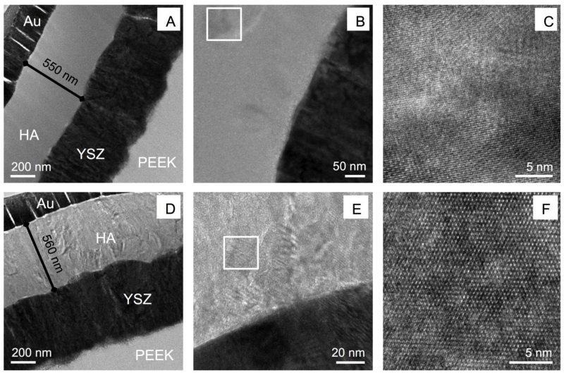
Figure 2 shows the HA/YSZ coating on the cylindrical PEEK implants after deposition and heat treatment as observed by TEM. The microwave heat treatments with and without subsequent autoclaving are shown in Figure 2a and Figure 2d, respectively. The gold (Au) layer used for focused ion beam (FIB) lift out and preparation of the observed samples was visible on top of the HA layer. The HA, YSZ, and PEEK layers were visible with no signs of delamination between layers, indicating the deposition and heat treatment processes did not induce major residual film stresses that could cause premature coating failure. The HA and YSZ layers of the coating exhibited a dense, uniform microstructure, each measuring approximately 500 nm (Figure 2a, d). The YSZ layers in both coatings consisted of columnar grains oriented perpendicular to the substrate surface. No change in microstructure of the YSZ layers was observed in either of the heat-treated samples. Closer inspection of the HA layer indicated that there were crystalline structures present in the microwave-treated sample (Figure 2b). Atomic resolution imaging confirmed these areas were in fact crystalline HA formed within the deposited amorphous layer by way of a brief microwave heat treatment (Figure 2c). Further microwave annealing followed by additional autoclave treatment (Figure 2a) indicated complete crystallization throughout the HA thickness. High-resolution observation showed multiple crystal grains within the HA region and atomic scale imaging showed the lattice structure of the crystalline HA formed in the coating via post-deposition microwave plus autoclave heat treatment (Figure 2e-f). Chemical phase analysis supporting the presence of crystalline HA in these coatings via diffraction standards is not presented here for sake of manuscript length, though it discussed in detail in another study [21].
Figure 2. TEM analysis.
TEM observation of microwave-treated implant coatings (A-C), and microwave with additional autoclaving implant coatings (D-F). Boxed regions indicate high resolution areas.
3.2 Compositional analysis
EDS was used in conjunction with STEM to quantify the atomic percentages of the elements present in the HA layer of the coating. This quantification is helpful in determining the Ca/P ratio, ideally 1.67 for stoichiometric HA. Table 1 shows the average atomic percentages of O, P, and Ca within the HA layer for coated samples that underwent microwave and microwave with subsequent autoclave treatments. The results showed that both coatings have a Ca/P ratio slightly above stoichiometric HA.
Table 1. Atomic composition of HA coating layer.
| Average atomic percentage (%) | ||||
|---|---|---|---|---|
| HA coating | O | P | Ca | Ca/P ratio |
| MW | 52.6 ± 4.2 | 16.1 ± 1.5 | 31.3 ± 2.8 | 1.95 |
| MW+AC | 44.7 ± 2.7 | 18.9 ± 0.9 | 36.3 ± 1.8 | 1.91 |
3.3 Micro-CT characterization
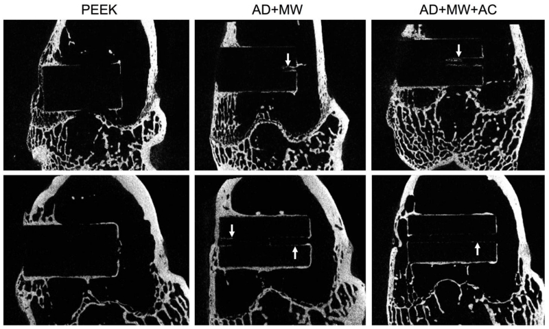
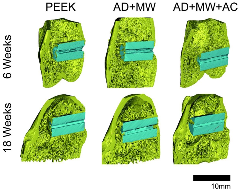
A comparison of the Micro-CT images taken at 6 and 18 weeks of in vivo implantation in the rabbit femoral condyle is seen in Figure 3. Image stitching of Micro-CT data allowed for three-dimensional observation of the implants (Figure 4). Qualitatively, greater bone contact was seen surrounding the implants with coatings compared to the PEEK control group and all groups showed increasing bone contact after 18 weeks compared to 6 weeks implantation. Coated implants showed trends of bone in-growth within the central canal after both 6 and 18 weeks post-implantation, especially the AD+MW group (Figure 3-4).
Figure 3. MicroCT.
Analysis of bone regeneration within specimens at 6 weeks (top) and 18 weeks (bottom) showing new bone growth around the implant surface for each of the sample groups. White arrows indicate bone growth within the central implant canal observed with the coated samples.
Figure 4. 3-D Micro-CT Representation.
Three-dimensional representations of the PEEK, AD+MW and AD+MW+AC implants (pseudo color blue) placed in the rabbit femoral condyles (bone pseudo colored yellow) after 6 weeks and 18 weeks of implantation.
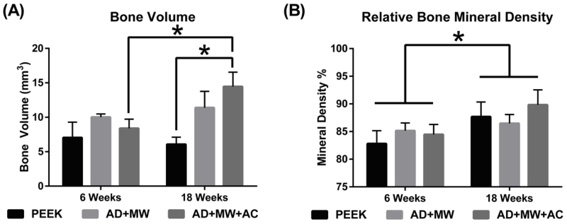
Bone volume regeneration was analyzed in two different regions of interest (ROI)– The 9 × 5 diameter region of interest primarily accounts for the bone growing within the hole that runs along the axis of the implant, bone known to be newly formed bone. Bone volume regenerated in this ROI was observed to be significantly higher in the AD+MW+AC coated implants compared to the PEEK implants throughout the study duration (main effect, p=0.023), and especially after 18 weeks (p=0.005). It was also observed that the bone volume regenerated on the AD+MW+AC implants increased significantly from 6 weeks to 18 weeks (p=0.02) indicating a robust and continued osseointegration (Figure 5a). The second ROI was slightly larger (9mm × 5.5mm) and incorporated a cylindrical zone of bone (0.25 mm in thickness) at the interface between the implant and the surrounding cancellous bone in the femoral metaphysis. While there was a pattern of increased bone volume in the peri-implant volume at 18 weeks with the coated groups (AD+MW was 22.13 ± 2.71 mm3 and AD+MW+AC was 22.61 ± 2.42 mm3, compared to PEEK only being 19.16 ± 3.03 mm3), these differences were not statistically significant. The bone mineral density of the bone regenerated on the implant surface was significantly higher (p=0.037) for all three implant types at 18 weeks of implantation compared to 6 weeks of implantation in vivo (Figure 5b).
Figure 5. Micro-CT Quantification.
(A) Bone volume regenerated on the implant surface itself was significantly higher in the AD+MW+AC coated implants compared to the PEEK implants after 18 weeks. The bone volume regenerated on the AD+MW+AC implants increased significantly from 6 to 18 weeks. (B) The mineral density of the regenerated bone in the surrounding envelope did show a significant increase for all three implant types between 6 and 18 weeks implantation. (* indicates significant difference between groups at p<0.05)
3.4 Histomorphometric evaluation
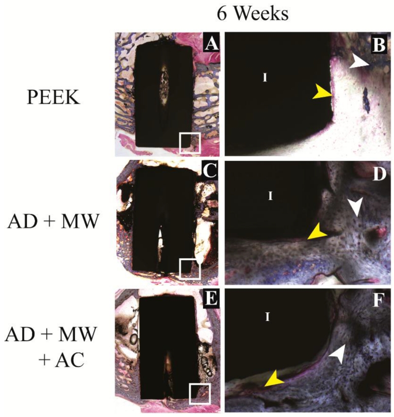
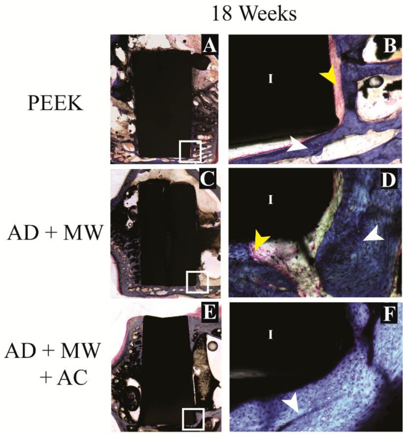
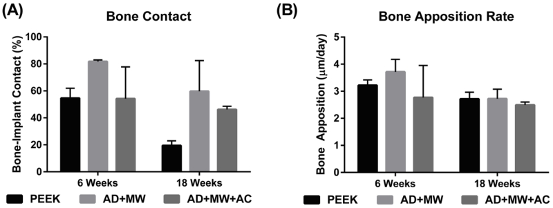
Mineralized tissue contact immediately against the implant surface was observed in the case of all three implant groups (Figure 6-7). Of the tissue in contact with the implant, in the case of all three implants, the proportion of mineralized tissue (blue stain) was significantly greater than fibrous tissue (pink stain); both at 6 weeks (63.5±8.6% mineralized vs. 10.0±1.4% fibrous) and after 18 weeks of implantation (41.8±9.6% mineralized vs. 18.6±5.6% fibrous). Fluorochromes (calcein green) administered 6 days apart in the last week prior to euthanasia for both the 6 week and 18 week animals were used to stain mineralizing osteoid and allow measurement of the MAR at the implant surface. No significant differences were found between the MAR on the surfaces of the three different implants after 6 or 18 weeks implantation. A general trend (p=0.241) of reduced bone apposition rate was observed across groups at 18 weeks (2.64±0.12 μm/day) compared to 6 weeks (3.23±0.37 μm/day). The AD+MW group showed a trend of higher bone to implant contact than the PEEK (p=0.4) and AD+MW+AC (p=0.4) after 6 weeks and both the AD+MW (p=0.179) and AD+MW+AC (p=0.41) coated implants showed a trend of greater bone to implant contact than the PEEK group after 18 weeks. A strong trend of reduced bone contact at 18 weeks compared to 6 weeks was observed especially in the PEEK group (p=0.12) while this trend was less severe in the AD+MW+AC group (54.6% at 6 weeks compared to 46.2% bone contact at 18 weeks) indicating sustained mineralization on the surface of the heat-treated samples (Figure 8).
Figure 6. Histological evaluation – short term.
Bone growth against the PEEK implants (A) as well as the AD+MW (C) and AD+MW+AC (E) coated implants at 6 weeks. The tissue sections stained with paragon and counter-stained with Aniline Blue show the ossified tissue blue (white arrows) and the fibrous tissue pink (yellow arrows). The implant (I) is seen as black in the slides. Mineralized tissue was seen to be highly cellular at 6 weeks (B,D,F). Scale bar 9 mm (A,C,E); 500 μm (B,D,F).
Figure 7. Histological evaluation – long term.
Bone growth against the PEEK implants (A) as well as the AD+MW (C) and AD+MW+AC (E) coated implants at 18 weeks. The trabeculae of bone in contact with the implant surface appeared to thin out in the PEEK group at 18 weeks (B) compared to the bone fronts in contact with the AD+MW (D) and AD+MW+AC (F) coated implants at the same time. White and yellow arrow point at ossified and fibrous tissue respectively, implant marked by ‘I’. Scale bar 9 mm (A,C,E); 500 μm (B,D,F).
Figure 8. Histological quantification.
(A) The percentage of implant perimeter in contact with mineralized tissue was found to range between 20 and 80% across the groups analyzed. The AD+MW group showed a trend of higher bone to implant contact than the PEEK and AD+MW+AC after 6 weeks and both the AD+MW and AD+MW+AC coated implants showed a trend of greater bone to implant contact than the PEEK group after 18 weeks. (B) No significant differences were found between the bone apposition rates on the surfaces of the three different implants after 6 or 18 weeks implantation. A general trend of reduced bone apposition rate was observed across groups at 18 weeks compared to 6 weeks.
3.5 Biomechanical push-out testing
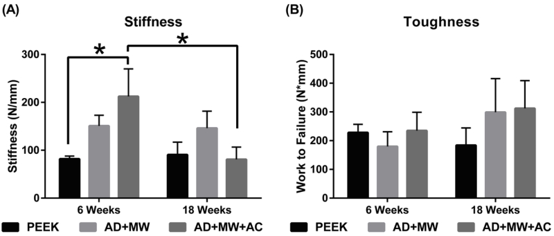
In terms of the interfacial stiffness, the AD+MW+AC group was significantly stiffer than the PEEK group after 6 weeks implantation (p=0.03), but no such significant differences were observed at 18 weeks. The AD+MW group showed a consistent trend of being stiffer at the bone implant interface than the PEEK group after both 6 and 18 weeks (p=0.168) without significant difference. The work to failure values in both the AD+MW (179.7±51.4 Nmm at 6 weeks to 299.1±117.1 Nmm at 18 weeks, p=0.28) and the AD+MW+AC groups (234.8±64.0 Nmm at 6 weeks to 312.5±96.3 Nmm at 18 weeks, p=0.48) increased from 6 to 18 weeks (Figure 9). Although not statistically significant, these values showed a generally higher trend when compared to bare PEEK at 18 weeks (183.9±60.5 Nmm).
Figure 9. Biomechanical push-out strength.
(A) In terms of the interfacial stiffness, the AD+MW+AC group was significantly stiffer than the PEEK group after 6 weeks implantation (* indicates p<0.05), but no such differences were observed at 18 weeks. The AD+MW group showed a consistent trend of being stiffer at the bone implant interface than the PEEK group after both 6 and 18 weeks. (B) The toughness of the bone implant interface in both the AD+MW and the AD+MW+AC coated groups increased from 6 to 18 weeks and yielded higher values than that of uncoated PEEK implants at 18 weeks.
4. Discussion
Dense, uniform HA/YSZ coatings were prepared via IBAD deposition on cylindrical PEEK implants with a smooth surface ground with 800-grit SiC paper. Results in the literature indicated that rough implant surfaces as well as coated implant surfaces could increase osseointegration [26]. These compounding effects were separated in this study by maintaining a smooth surface, which allowed for independent analysis of the in vivo response solely attributed to the coating. Coatings prepared on PEEK by IBAD at room temperature resulted in amorphous phase HA. Post-deposition heat treatment via microwave with and without autoclave processing methods allowed for crystallization of the HA layer without disturbing the implant-coating interface, evident of strong adhesion to the polymer substrate. This was attributed to the formation of an atomic mixing interface region between various layers of the coating architecture due to the effect of secondary ion bombardment during deposition. Investigation of the elemental composition of the HA layer showed that the Ca/P ratio was only slightly higher than that of stoichiometric HA. The ideal Ca/P ratio is dependent on the desired application, and has been investigated in a recent study, showing a trade off between short term bone regeneration and long-term stability [27]. The results of this study indicated appropriate adjustment of the secondary ion beam was achieved with minimal preferential re-sputtering of atoms with higher sputtering factors such as P–a typical finding in sputtered HA films deposited in vacuum [23,28]. The small decrease in the Ca/P ratio found in AD+MW+AC coatings is likely due to the dissolution of calcium oxide at the coating surface during autoclave treatment.
Observation of the coated samples implanted in rabbit bone for 6 and 18 weeks showed increased osseointegration compared to uncoated PEEK implants, in agreement with previous studies on HA coatings [6]. Micro-CT, histological and biomechanical analysis techniques were used to identify the individual biologic effects of the coating. Coated samples showed trends of bone growth within the implant and micro-CT analysis allowed for a three-dimensional survey of the regenerated bone volume, resulting in a complete visual representation of the peri-implant healing response.
The crystalline HA surface prepared by this deposition and heat treatment method has proven to increase bone apposition in past studies in vitro [21] and showed a 2-fold increase in bone regeneration in this instance. There are various factors that affect the bone regeneration process in vivo, and the authors suggest the increase seen here is mostly owed to the increase in HA crystallinity achieved by microwave heat treatment followed by autoclaving. The measured bone mineral density increase from 6 to 18 weeks was indicative of healthy bone growth and development.
The quantitative histological data obtained from the ROI also indicated positive effects from the HA/YSZ coatings in terms of bone apposition and in-growth response. Mineralized tissue surrounding the implant perimeter, which is an indication of osseointegration, was observed along with increased bone contact area. The bone apposition rates determined by the development of mineralization fronts illuminated by calcein staining were very similar to those reported for an injectable complex of β-tricalcium phosphate granules and hyaluronate in rabbit bone defects after 6 to 8 weeks [29]. Further inspection of the bone contact data revealed a general trend of reduced areal contact from 6 to 18 weeks in all implant groups, supported by a similar trend observed in the bone apposition rate over the same time period; it was suggested that these tendencies were an effect of the smooth implant surface, consistent with other reports in the literature [30].
Biomechanical push-out tests showed that the coating increased the short-term rigidity of the implant-bone interface thus providing a mechanically stable environment for healing to occur, especially in AD+MW+AC coating samples. In the long term, coated implants required more work to remove them from the placement site, evident of greater fixation within the host bone. On the basis of i) trends in bone volume regenerated on the implant surface in the long term study (micro-CT analysis), ii) trends of change in overall bone-implant contact over time (histological analysis), iii) the biomechanical implant interfacial stiffness in the short term study, and iv) the work required to push out the implant in the long term study, the coated implants improved the bone response compared to uncoated PEEK in these key aspects of osseointegration; The crystalline HA implant surface created by the coating and heat treatment methods described here provide a more favorable surface for sustained bone apposition and growth compared to uncoated PEEK surfaces.
5. Conclusions
Smooth, cylindrical PEEK implants were coated with YSZ and HA by IBAD to increase the osseointegration in vivo. TEM observation of microwave and microwave plus autoclave processed coatings showed the ability to crystallize HA after deposition without disturbing critical interfacial regions. The animal study showed that coated implants exhibited major improvements in bone regeneration and implant fixation compared to uncoated PEEK. Coated implants promoted sustained bone regeneration throughout the entire test period, unlike the PEEK control. In particular, the AD+MW+AC coated implants showed twice the amount of regenerated bone on their surface compared to uncoated PEEK implants. Improved osseointegration of PEEK implants can be expected with the addition of heat-treated HA/YSZ coatings deposited using IBAD. Further improvements in implant fixation are expected with additional surface roughening prior to deposition and can be optimized for the development of coated implants for larger anatomies. The results showed that IBAD-deposited HA/YSZ coatings increased osseointegration of PEEK implants and offered specific advantages capable of improving surgical outcomes.
Highlights.
Method for improving osseointegration of PEEK implants is analyzed in vivo
Uniform multilayer coatings were deposited on cylindrical PEEK implants
Microwave and hydrothermal heat treatments crystallized the hydroxyapatite coating
Healing response shows coated implants increase bone growth and implant fixation
Acknowledgements
The research reported in this publication was supported by the National Institute of Dental and Craniofacial Research of the National Institutes of Health under award number R21DE022925. The content is solely the responsibility of the authors and does not necessarily represent the official views of the National Institutes of Health.
Footnotes
Publisher's Disclaimer: This is a PDF file of an unedited manuscript that has been accepted for publication. As a service to our customers we are providing this early version of the manuscript. The manuscript will undergo copyediting, typesetting, and review of the resulting proof before it is published in its final citable form. Please note that during the production process errors may be discovered which could affect the content, and all legal disclaimers that apply to the journal pertain.
References
- [1].Martin BI, Mirza SK, Comstock BA, Gray DT, Kreuter W, Deyo RA. Reoperation Rates Following Lumbar Spine Surgery and the Influence of Spinal Fusion Procedures: Spine. 2007;32:382–387. doi: 10.1097/01.brs.0000254104.55716.46. doi:10.1097/01.brs.0000254104.55716.46. [DOI] [PubMed] [Google Scholar]
- [2].Kurtz SM, Devine JN. PEEK Biomaterials in Trauma, Orthopedic, and Spinal Implants. Biomaterials. 2007;28:4845–4869. doi: 10.1016/j.biomaterials.2007.07.013. doi:10.1016/j.biomaterials.2007.07.013. [DOI] [PMC free article] [PubMed] [Google Scholar]
- [3].Toth JM, Wang M, Estes BT, Scifert JL, Seim HB, III, Turner AS. Polyetheretherketone as a biomaterial for spinal applications. Biomaterials. 2006;27:324–334. doi: 10.1016/j.biomaterials.2005.07.011. doi:10.1016/j.biomaterials.2005.07.011. [DOI] [PubMed] [Google Scholar]
- [4].Godara A, Raabe D, Green S. The influence of sterilization processes on the micromechanical properties of carbon fiber-reinforced PEEK composites for bone implant applications. Acta Biomater. 2007;3:209–220. doi: 10.1016/j.actbio.2006.11.005. doi:10.1016/j.actbio.2006.11.005. [DOI] [PubMed] [Google Scholar]
- [5].Ma R, Tang T. Current Strategies to Improve the Bioactivity of PEEK. Int. J. Mol. Sci. 2014;15:5426–5445. doi: 10.3390/ijms15045426. doi:10.3390/ijms15045426. [DOI] [PMC free article] [PubMed] [Google Scholar]
- [6].Surmenev RA, Surmeneva MA, Ivanova AA. Significance of calcium phosphate coatings for the enhancement of new bone osteogenesis – A review. Acta Biomater. 2014;10:557–579. doi: 10.1016/j.actbio.2013.10.036. doi:10.1016/j.actbio.2013.10.036. [DOI] [PubMed] [Google Scholar]
- [7].Zhang BGX, Myers DE, Wallace GG, Brandt M, Choong PFM. Bioactive Coatings for Orthopaedic Implants—Recent Trends in Development of Implant Coatings. Int. J. Mol. Sci. 2014;15:11878–11921. doi: 10.3390/ijms150711878. doi:10.3390/ijms150711878. [DOI] [PMC free article] [PubMed] [Google Scholar]
- [8].Bai X, Sandukas S, Appleford MR, Ong JL, Rabiei A. Deposition and investigation of functionally graded calcium phosphate coatings on titanium. Acta Biomater. 2009;5:3563–3572. doi: 10.1016/j.actbio.2009.05.013. doi:10.1016/j.actbio.2009.05.013. [DOI] [PubMed] [Google Scholar]
- [9].Wang L, Nancollas GH. Calcium Orthophosphates: Crystallization and Dissolution. Chem. Rev. 2008;108:4628–4669. doi: 10.1021/cr0782574. doi:10.1021/cr0782574. [DOI] [PMC free article] [PubMed] [Google Scholar]
- [10].Rabiei A, Thomas B, Neville B, Lee JW, Cuomo J. A novel technique for processing functionally graded HA coatings. Mater. Sci. Eng. C. 2007;27:523–528. doi:10.1016/j.msec.2006.05.037. [Google Scholar]
- [11].Briem D, Strametz S, Schröoder K, Meenen NM, Lehmann W, Linhart W, Ohl A, Rueger JM. Response of primary fibroblasts and osteoblasts to plasma treated polyetheretherketone (PEEK) surfaces. J. Mater. Sci. Mater. Med. 2005;16:671–677. doi: 10.1007/s10856-005-2539-z. doi:10.1007/s10856-005-2539-z. [DOI] [PubMed] [Google Scholar]
- [12].Waser-Althaus J, Salamon A, Waser M, Padeste C, Kreutzer M, Pieles U, Müller B, Peters K. Differentiation of human mesenchymal stem cells on plasma-treated polyetheretherketone. J. Mater. Sci. Mater. Med. 2013;25:515–525. doi: 10.1007/s10856-013-5072-5. doi:10.1007/s10856-013-5072-5. [DOI] [PubMed] [Google Scholar]
- [13].Noiset O, Schneider YJ, Marchand-Brynaert J. Fibronectin adsorption or/and covalent grafting on chemically modified PEEK film surfaces. J. Biomater. Sci. Polym. Ed. 1999;10:657–677. doi: 10.1163/156856299x00865. [DOI] [PubMed] [Google Scholar]
- [14].Zhao Y, Wong HM, Wang W, Li P, Xu Z, Chong EYW, Yan CH, Yeung KWK, Chu PK. Cytocompatibility, osseointegration, and bioactivity of three-dimensional porous and nanostructured network on polyetheretherketone. Biomaterials. 2013;34:9264–9277. doi: 10.1016/j.biomaterials.2013.08.071. doi:10.1016/j.biomaterials.2013.08.071. [DOI] [PubMed] [Google Scholar]
- [15].Ma R, Weng L, Bao X, Song S, Zhang Y. In vivo biocompatibility and bioactivity of in situ synthesized hydroxyapatite/polyetheretherketone composite materials. J. Appl. Polym. Sci. 2013;127:2581–2587. doi:10.1002/app.37926. [Google Scholar]
- [16].Wang L, He S, Wu X, Liang S, Mu Z, Wei J, Deng F, Deng Y, Wei S. Polyetheretherketone/nano-fluorohydroxyapatite composite with antimicrobial activity and osseointegration properties. Biomaterials. 2014;35:6758–6775. doi: 10.1016/j.biomaterials.2014.04.085. doi:10.1016/j.biomaterials.2014.04.085. [DOI] [PubMed] [Google Scholar]
- [17].Barkarmo S, Wennerberg A, Hoffman M, Kjellin P, Breding K, Handa P, Stenport V. Nano-hydroxyapatite-coated PEEK implants: A pilot study in rabbit bone. J. Biomed. Mater. Res. A. 2013;101A:465–471. doi: 10.1002/jbm.a.34358. doi:10.1002/jbm.a.34358. [DOI] [PubMed] [Google Scholar]
- [18].Hahn B-D, Park D-S, Choi J-J, Ryu J, Yoon W-H, Choi J-H, Kim J-W, Ahn C-W, Kim H-E, Yoon B-H, Jung I-K. Osteoconductive hydroxyapatite coated PEEK for spinal fusion surgery. Appl. Surf. Sci. 2013;283:6–11. doi:10.1016/j.apsusc.2013.05.073. [Google Scholar]
- [19].Lee JH, Jang HL, Lee KM, Baek H-R, Jin K, Hong KS, Noh JH, Lee H-K. In vitro and in vivo evaluation of the bioactivity of hydroxyapatite-coated polyetheretherketone biocomposites created by cold spray technology. Acta Biomater. 2013;9:6177–6187. doi: 10.1016/j.actbio.2012.11.030. doi:10.1016/j.actbio.2012.11.030. [DOI] [PubMed] [Google Scholar]
- [20].Rabiei A, Sandukas S. Processing and evaluation of bioactive coatings on polymeric implants. J. Biomed. Mater. Res. A. 2013;101A:2621–2629. doi: 10.1002/jbm.a.34557. doi:10.1002/jbm.a.34557. [DOI] [PubMed] [Google Scholar]
- [21].Durham JW, III, Allen MJ, Rabiei A. Preparation, characterization and in vitro response of bioactive coatings on polyether ether ketone. JBMR-B. 2015 doi: 10.1002/jbm.b.33578. doi: 10.1002/jbm.b.33578. [DOI] [PMC free article] [PubMed] [Google Scholar]
- [22].Mohseni E, Zalnezhad E, Bushroa AR. Comparative investigation on the adhesion of hydroxyapatite coating on Ti–6Al–4V implant: A review paper. Int. J. Adhes. Adhes. 2014;48:238–257. doi:10.1016/j.ijadhadh.2013.09.030. [Google Scholar]
- [23].Blalock T, Bai X, Rabiei A. A study on microstructure and properties of calcium phosphate coatings processed using ion beam assisted deposition on heated substrates. Surf. Coat. Technol. 2007;201:5850–5858. doi:10.1016/j.surfcoat.2006.10.039. [Google Scholar]
- [24].Durham JW, III, Rabiei A. Deposition, heat treatment and characterization of two layer bioactive coatings on cylindrical PEEK. Surf. Coat. Technol. 2015 doi: 10.1016/j.surfcoat.2015.12.045. doi:10.1016/j.surfcoat.2015.12.045. [DOI] [PMC free article] [PubMed] [Google Scholar]
- [25].Rabiei A. [accessed April 28, 2015];Processing of biocompatible coating on polymeric implants. 2012 US8323722 B2. http://www.google.com/patents/US8323722.
- [26].Rao PJ, Pelletier MH, Walsh WR, Mobbs RJ. Spine interbody implants: material selection and modification, functionalization and bioactivation of surfaces to improve osseointegration. Orthop. Surg. 2014;6:81–89. doi: 10.1111/os.12098. doi:10.1111/os.12098. [DOI] [PMC free article] [PubMed] [Google Scholar]
- [27].Urquia Edreira ER, Wolke JGC, Aldosari AA, Al-Johany SS, Anil S, Jansen JA, van den Beucken JJJP. Effects of calcium phosphate composition in sputter coatings on in vitro and in vivo performance. J. Biomed. Mater. Res. A. 2015;103:300–310. doi: 10.1002/jbm.a.35173. doi:10.1002/jbm.a.35173. [DOI] [PubMed] [Google Scholar]
- [28].Ong JL, Lucas LC, Raikar GN, Weimer JJ, Gregory JC. Surface characterization of ion-beam sputter-deposited Ca-P coatings after in vitro immersion. Colloids Surf. Physicochem. Eng. Asp. 1994;87:151–162. doi:10.1016/0927-7757(94)02774-9. [Google Scholar]
- [29].Chazono M, Tanaka T, Komaki H, Fujii K. Bone formation and bioresorption after implantation of injectable beta-tricalcium phosphate granules-hyaluronate complex in rabbit bone defects. J. Biomed. Mater. Res. A. 2004;70:542–549. doi: 10.1002/jbm.a.30094. doi:10.1002/jbm.a.30094. [DOI] [PubMed] [Google Scholar]
- [30].Johansson P, Jimbo R, Kozai Y, Sakurai T, Kjellin P, Currie F, Wennerberg A. Nanosized Hydroxyapatite Coating on PEEK Implants Enhances Early Bone Formation: A Histological and Three-Dimensional Investigation in Rabbit Bone. Materials. 2015;8:3815–3830. doi: 10.3390/ma8073815. doi:10.3390/ma8073815. [DOI] [PMC free article] [PubMed] [Google Scholar]


