Abstract
An open-source hyperpolarizer producing 13C hyperpolarized contrast agents using parahydrogen induced polarization (PHIP) for biomedical and other applications is presented. This PHIP hyperpolarizer utilizes an Arduino microcontroller in conjunction with a readily modified graphical user interface written in the open-source processing software environment to completely control the PHIP hyperpolarization process including remotely triggering an NMR spectrometer for efficient production of payloads of hyperpolarized contrast agent and in situ quality assurance of the produced hyperpolarization. Key advantages of this hyperpolarizer include: (i) use of open-source software and hardware seamlessly allowing for replication and further improvement as well as readily customizable integration with other NMR spectrometers or MRI scanners (i.e., this is a multiplatform design), (ii) relatively low cost and robustness, and (iii) in situ detection capability and complete automation. The device performance is demonstrated by production of a dose (∼2–3 mL) of hyperpolarized 13C-succinate with %P13C ∼ 28% and 30 mM concentration and 13C-phospholactate at %P13C ∼ 15% and 25 mM concentration in aqueous medium. These contrast agents are used for ultrafast molecular imaging and spectroscopy at 4.7 and 0.0475 T. In particular, the conversion of hyperpolarized 13C-phospholactate to 13C-lactate in vivo is used here to demonstrate the feasibility of ultrafast multislice 13C MRI after tail vein injection of hyperpolarized 13C-phospholactate in mice.
Nuclear spin polarization (P) can be increased by orders of magnitude compared to the equilibrium thermal polarization level induced by a magnetic field through a process denoted as hyperpolarization.1,2 While the hyperpolarized (HP) state is temporary in nature with exponential decay time constants on the order of seconds to tens of minutes,3,4 HP biomolecules have been successfully used as metabolic contrast agents.5,6 Once injected in living organisms at sufficient quantity and high polarization, these HP contrast agents (HCA) can serve as quantitative imaging biomarkers reporting on abnormal metabolism in cancer, heart diseases, and other diseases.7−10
Several hyperpolarization techniques exist, but only dissolution dynamic nuclear polarization (d-DNP)11 and parahydrogen induced polarization (PHIP)12−14 methods have been shown to be useful to date for producing liquid-state HCAs which have shown promise in vivo.7,15 D-DNP is the most widely used hyperpolarization technique, where a source of unpaired electrons is introduced to a biomolecule such as pyruvic acid (commonly by mixing with a free radical), and the HP state of nuclei is created by high-power microwave irradiation of electrons at low temperature and high magnetic field; i.e., high Boltzmann polarization of unpaired electrons is transferred to 13C1 carbon of pyruvic acid under microwave irradiation.11 This process is highly efficient, and up to 70% 13C polarization levels can be achieved in as little as 20 min.16 The d-DNP technique has been applied to a broad range of molecules.7,8,17 The widespread accessibility of d-DNP beyond custom-built research platforms was significantly enhanced by the introduction of commercial hyperpolarization equipment suitable for preclinical trials of this technology in small rodents6,18−21 and, later, the introduction of a sterile-path d-DNP hyperpolarizer intended for clinical use.22 These technical developments for d-DNP ultimately enabled the first clinical trial in 2013,23 a remarkable achievement only 10 years after the first proof-of-principle study.11,24
Despite these advances, however, d-DNP technology has yet to address two major challenges: (i) the high cost of the device producing hyperpolarized nuclear spin states (also denoted the “hyperpolarizer”) and, more importantly, (ii) the relatively slow speed of the hyperpolarization process, varying from 0.3 to 2 h dependent on the HCA choice.16,25
PHIP provides an alternative to d-DNP hyperpolarization, and it is free from the above limitations. This technique relies on the high-speed, pairwise addition of parahydrogen (para-H2) by a catalyst across an unsaturated carbon–carbon bond (C=C or C≡C)12−14 followed by polarization transfer from nascent protons to longer-lived (i.e., with greater T1 time constant) 13C nucleus via the J-couplings.5,26−29 As a result of this rapid catalysis, HCA can be produced in seconds.26−29 The requirement of a 13C labeled site being adjacent to an unsaturated carbon–carbon bond with a sufficiently strong J-coupling is the main drawback of the PHIP hyperpolarization method, which has significantly slowed down the progress of implementing this hyperpolarization technique for metabolic imaging after its initial demonstration for 13C hyperpolarization of 2-hydroxyethyl propionate (HEP), useful for angiographic applications,27,28,30 although at least three other HP 13C biomolecules have been recently developed for PHIP hyperpolarization with sufficient payloads of net magnetization suitable for biomedical applications: succinate31 for cancer imaging,32 tetrafluoropropyl propionate33,34 for atheroma imaging,35 and phospholactate36−38 for lactate imaging probing elevated glycolysis in cancer similarly to HP pyruvate by DNP. As a result, commercial PHIP hyperpolarizers (beyond prototype devices30 produced by Amersham Biosciences, Healthcare company) have never emerged, which in turn further inhibited the adoption of PHIP for biomedical purposes.
However, a recent (ca. 2015) introduction of PHIP using side arm hydrogenation (PHIP-SAH)29,39 significantly expanded the reach of amenable biologically relevant molecules for PHIP. Importantly, hyperpolarization of acetate and pyruvate is now feasible with PHIP-SAH, and therefore, PHIP can potentially complement d-DNP. Moreover, we have recently demonstrated an efficient and robust synthesis of biomolecular precursors for PHIP-SAH hyperpolarization of 13C-acetate and beyond.40 Although the demonstrated P13C of ∼2% was relatively low by PHIP-SAH, Reineri and co-workers noted that further %P13C improvement to ∼25% would require an efficient PHIP hyperpolarizer device capable of fast para-H2 pairwise addition and efficient polarization transfer from protons to 13C nuclei.39
A few examples of PHIP hyperpolarizers and platforms have been demonstrated over the years with mixed success. Early reports described the first partially automated PHIP hyperpolarizer, based on a LabView platform, but its performance was susceptible to external magnetic field fluctuations, and it lacked in situ detection capability.41,42 The in situ detection capability was later demonstrated in an automated 0.0475 T PHIP hyperpolarizer, where control codes and timing delays embedded into the NMR spectrometer pulse sequence provided a convenient means of controlling and sequencing the radio frequency (RF) polarization transfer pulse sequence with gas manifold events related to handling of liquids and gases: producing an aliquot of precursor molecule, injecting it with para-H2 into a chemical reactor during 1H RF decoupling, applying the RF pulse sequence, liquid ejection, etc.43,44 Other recently reported designs of automated PHIP hyperpolarizers were also based on custom LabView platforms and lacked the in situ detection capability.45,46 This capability is essential for quality assurance (QA) of the HCA prior to injection in vivo as well as for optimization of the hyperpolarizer performance. For example, %P13C of only 1% was achieved by a design (lacking in situ detection capability) presented by Wagner and co-workers.45 It should also be noted that LabView-based PHIP hyperpolarizers utilize custom (and typically proprietary) software, which is very difficult for sharing among those wanting to replicate or build more advanced variants of PHIP hyperpolarizers.
While in situ detection capability certainly advanced the field of PHIP hyperpolarizers, the original demonstration was based on a relatively expensive Halbach array permanent magnet,43 and more importantly, the software controlling auxiliary components (e.g., solenoid valves) were tied into the software of the NMR spectrometer (i.e., preventing seamless multiplatform sharing and adaptation). Furthermore, the spectrometer-based design has a limited potential for integration of more complex sensors for process control including pressure, temperature, etc. Such capability has proven essential for feedback controls improving hyperpolarizer performance and safety interlocks as demonstrated in automated 129Xe hyperpolarizers.47,48
Building on experience constructing clinical-scale 129Xe spin-exchange optical pumping (SEOP) hyperpolarizers,47−51 here we present an open-source automated PHIP hyperpolarizer design with significant advantages compared to previous PHIP hyperpolarizers. The “brain” of the hyperpolarizer is an open-source Arduino microcontroller (∼$30 USD), which provides complete control of the device and permits integration with any NMR spectrometer capable of applying a PHIP RF polarization transfer sequence. All details of the design are provided in the main text and the Supporting Information, including all drawings and part sources sufficient to replicate and customize this design. The provided open-source PHIP hyperpolarizer software (Arduino microcontroller code and a graphical user interface based on free and open-source Processing software) readily enables future extension of the capabilities of the presented polarizer design: e.g., integration of sensors, safety interlocks, etc.47,48 The device has a relatively low cost and produces payloads of HCA sufficient for preclinical studies in rodents. Having utilized this PHIP hyperpolarizer in conjunction with a HyperBridge (a magnetized HP tracer transfer pathway) previously used to show the potential for high-resolution molecular imaging studies,52 here we demonstrate the efficacy of the presented hyperpolarizer with an example of in vivo13C spectroscopy of HP 1-13C-succinate and pioneering in vivo imaging and spectroscopy of a previously reported HCA/1-13C-phospholactate.36,38
Experimental Methods
Overall Design of PHIP Hyperpolarizer
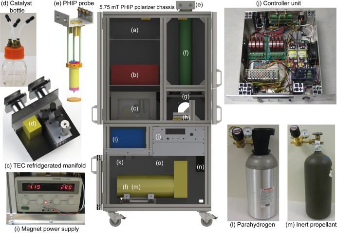
The design of the PHIP hyperpolarizer is shown, and a listing of all the major components is provided in Figure 1; the graphical user interface (GUI) software windows are shown in Figure 2. Figure S1 and Tables S1 and S2 provide a detailed system diagram and list the part numbers and source information for all commercially available components and technical drawings of the custom-made components of the PHIP hyperpolarizer, and further, the Supporting Information zip file also includes the GUI and PHIP microcontroller programming code.
Figure 1.
Schematic of the PHIP hyperpolarizer. The system consists of the following key elements: (a) a device frame, (b) NMR spectrometer and RF amplifier(s), (c) thermoelectric cooled (TEC) manifold, (d) catalyst/precursor containing bottle, (e) PHIP probe, (f) B0 magnet, (g) B0 magnet/RF probe cooling fans, (h) interface to HyperBridge, (i) B0 magnet power supply unit (PSU), (j) controller unit, (k) solenoid valves, (l) para-H2 tank, (m) propellant inert gas tank, (n) power distribution unit, and (o) step-down pressure regulator. The overall hyperpolarizer dimensions are ∼68 in. (height) by ∼21 in. (depth) by 33 in. (width). See additional details in the text and Supporting Information.
Figure 2.
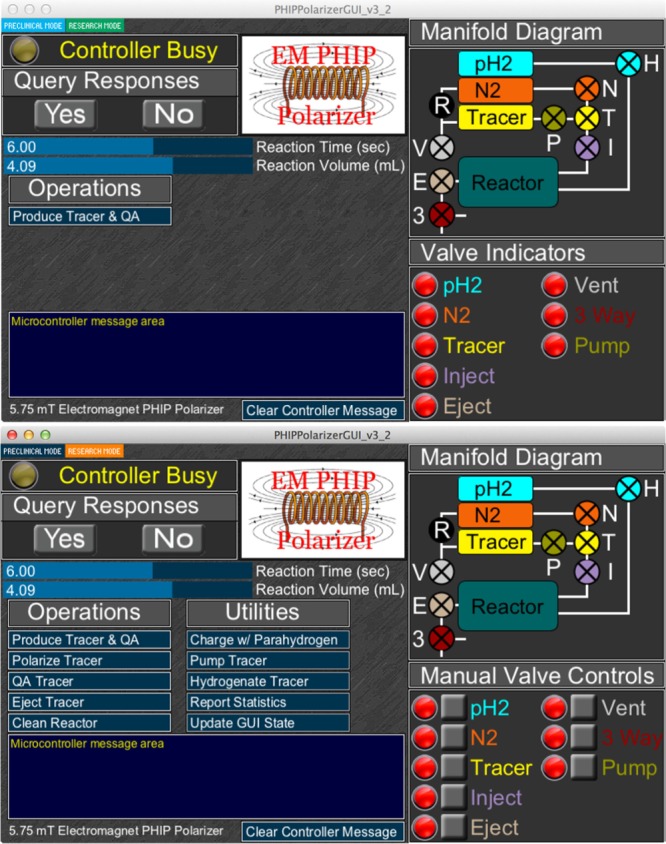
Screenshots of the Graphical User Interface (GUI) software showing two different modes of PHIP hyperpolarizer operation: (top) a preclinical mode where device operation is simplified to “single-button” operation; (bottom) research mode gaining access to a series of automated protocols and manual control of manifold components.
Device Frame
The device frame was designed using CAD software (see Supporting Information for further details in addition to Figure 1), and the frame is made available as a part number from MiniTec, Victor, NY (P/N MT101315-1). The PHIP controller unit (i.e., for the electronics) enclosure should be ordered separately as P/N MT101315-2. The frame (∼50 × 82 × 163 cm) incorporates all components excluding the RF amplifiers situated on top of or adjacent to the main frame.
Magnet and RF Coils
The magnet coil (Figure 1) utilizes a solenoid design (Figure S2) and generates a B0 field of ∼5.75 mT using ∼120 W of power, which allows for convenient heating of the reactor and the sample injection loop. The temperature (40–75 °C range) is controlled by the main fans of the chassis. Two tuned (and matched to 50 Ohm) RF Helmholtz saddle coils (Supporting Information) with their alternating B1 fields geometrically orthogonal to each other and also orthogonal to the static B0 field of the solenoid magnet surround the reactor. These RF coils provide very short RF pulses (≤0.5 ms) at low power (≤2.5 W) and good B1 homogeneity (Figure S3).
High-Pressure Reactor
The high-pressure reactor of the PHIP hyperpolarizer (shown in detail in Figure 3c) is housed inside the RF coils, which cover its ∼56 mL volume completely. The reactor (Supporting Information) is made of thick-wall polysulfone material and allows operation at up to 90 °C and up to ∼21 atm pressure.
Figure 3.
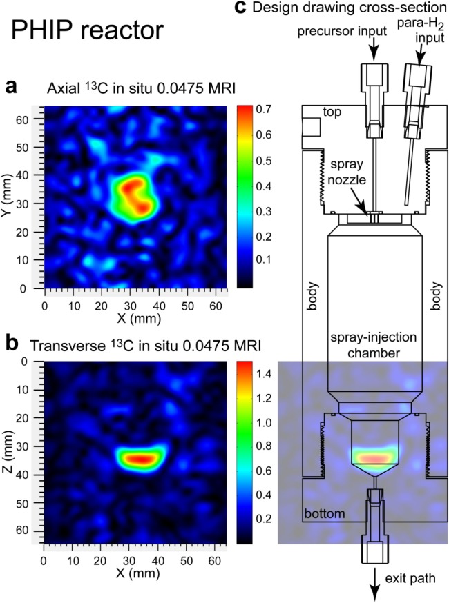
In operando 2D 13C MRI postproduction in the PHIP reactor. Hyperpolarized 13C 2D MRI (projection imaging of HP HEP) of the PHIP reactor was conducted at 0.0475 T43,44 in (a) an axial projection (top-to-bottom view) and in (b) a transverse projection (side view) and (c) a cross-sectional overlay of the PHIP reactor onto the 13C hyperpolarized image shown in (b). Further reactor design details are given in the main text and the Supporting Information. The presented MRI images were acquired with 2 × 2 mm2 spatial resolution and a 64 × 64 mm2 field of view and were bilinearly interpolated to higher resolution in order to enhance the appearance.
NMR Spectrometer and RF Amplifier and RF Probe
A dual channel Kea-2 NMR spectrometer (Magritek, Wellington, New Zealand) and custom-built Tomco RF amplifier (P/N BT00250-AlphaS-Dual, Tomco Technologies, Stepney, Australia) were utilized.
Preparation of Solutions Containing Catalyst and PHIP Precursors
HP 1-13C-Succinate-d2 (SUX)
Stock solution (30 mM, pH = 10.3 measured by a pH meter) of 1-13C-fumaric acid-d2 acid (Cambridge Isotopes, CDLM-6062-PK, 1-13C 99%, 2,3-D2 98%, 3.00 mmol, 0.357 g) and trisodium phosphate 12-hydrate, Na3PO4 × 12 H2O (3.00 mmol, 1.14 g) were dissolved in deuterium oxide, D2O (Sigma, 99.8% D, 756822, 100 mL), and pH was adjusted by a diluted sodium deuteroxide (NaOD) solution made of commercially available NaOD (Sigma, 164488, 30 wt % in D2O, 99 atom % D). The resulting solution was placed in a Buchi evaporation flask (1 L) and was degassed using a rotational evaporator (model R-215 equipped with V-710 pump, Buchi, New Castle, DE) fitted with an argon gas (high purity Argon) input by repeating twice the following sequence: (a) the pressure was slowly (to avoid boiling over) decreased from 70 to 15 mbar over approximately 5 min; (b) the pressure was adjusted back to ambient level by filling the content of the 1 L flask with Argon gas (1 bar). The phosphorus ligand, disodium salt of 1,4-bis[(phenyl-3-propanesulfonate)phosphine]butane (717347, Sigma-Aldrich-Isotec, 0.360 g, 0.64 mmol) was added, and the procedure followed with an additional degassing described above. Finally, rhodium(I) catalyst, bis(norbornadiene) rhodium(I) tetrafluoroborate (0.200 g, 0.54 mmol, 45-0230, CAS 36620-11-8, Strem Chemicals, MA) was dissolved in ∼5 mL of acetone and was added dropwise to the phosphine ligand solution to limit undesirable rhodium precipitation. The described above degassing procedure was repeated one more time to eliminate acetone.
HP 1-13C-Phospholactate-d2 (PLAC)
The unsaturated precursor, monopotassium salt of 1-13C-phosphoenol-pyruvate-d2 (1-13C-PEP-d2 or PEP), was produced by the protocol described in ref (38). The batch used in this study contained ∼15 mol % of its reduced form 1-13C-phospholactate-d2 (PLAC). While the presence of PLAC in the starting material does not influence the ultimate chemical outcome of hyperpolarization, its presence was accounted for in polarization level calculations. Therefore, potassium salt of 1-13C-phosphoenol-pyruvate-d2, 1-13C-PEP-d2 (85% with 15% of PLAC, 2.50 mmol, 0.628 g), and trisodium phosphate 12-hydrate, Na3PO4 × 12 H2O (3.00 mmol, 1.14 g), were dissolved in deuterium oxide, D2O (Sigma, 99.8% D, 756822, 100 mL), and pH was adjusted to ∼10.3 (monitored by a pH meter) by diluted sodium deuteroxide (NaOD) solution made from commercially available NaOD (Sigma, 164488, 30 wt % in D2O, 99 atom % D). The resulting solution was filtered and placed in a Buchi evaporation flask (1 L), and it was degassed using the rotational evaporator fitted with an argon gas (high purity Argon) input by repeating twice the following sequence: (a) the pressure was slowly (to avoid boiling over) decreased from 70 to 15 mbar over approximately 5 min; (b) pressure was adjusted back to the ambient level by opening the Argon valve. The phosphorus ligand, disodium salt of 1,4-bis[(phenyl-3-propanesulfonate)phosphine]butane (717347, Sigma-Aldrich-Isotec, 0.720 g, 1.28 mmol) was added, and it was followed with an additional degassing step as described above. Finally, rhodium(I) catalyst, bis(norbornadiene) rhodium(I) tetrafluoroborate (0.400 g, 1.04 mmol, 45-0230, CAS 36620-11-8, Strem Chemicals, MA) dissolved in ∼5 mL of acetone, was added dropwise to the phosphine ligand solution to limit undesirable rhodium precipitation. The above described degassing procedure was repeated one more time to eliminate acetone.
The hydrogenation reactions inside the PHIP hyperpolarizer were deemed to reach ∼100% yield as tested by high-resolution NMR assays of reaction mixtures.38 Please note that for the case of preparations of aqueous solutions, deuterium oxide was replaced by HPLC grade water (Fisher Scientific) and sodium deuteroxide was replaced by regular sodium hydroxide.
PHIP Hyperpolarizer Operation
The PHIP hyperpolarizer is operated via Graphical User Interface (GUI), Figure 2. The primary automated HCA production routine performs the following steps: (i) charging the heated reactor chamber with ∼6 atm para-H2 gas (∼12 s), (ii) loading the solution containing catalyst and PHIP precursor into the heated injection loop (∼2 s), (iii) triggering the NMR spectrometer (<0.1 s), (iv) injecting the warmed solution from the injection loop and spraying it into atmosphere of hot para-H2 gas using the back-pressure (∼17 atm) of propellant gas (e.g., ultrahigh purity N2 or Argon) under conditions of 1H decoupling provided by the RF pulse sequence of the triggered NMR spectrometer (3–12 s), (v) polarization transfer using a RF pulse sequence developed by Goldman and Johannesson26 (∼0.3 s), and (vi) in situ13C polarimetry of the produced HCA to determine its %P13C using a small-angle RF pulse (∼0.5 s). The entire fully automated polarization procedure requires less than 1 min.
The produced HCA is located at the bottom of the chemical reactor by the end of the injection step (as seen in the in situ 2D 13C MRI images (Figure 3) recorded using the same reactor in combination with a previously demonstrated PHIP setup at 47.5 mT44) and then is conveniently ejected by opening the eject valve, and aqueous HCA can be transferred to a container (e.g., syringe) for its further use. While HP HEP is relatively immune to exposure to ambient low magnetic fields, HP SUX and PLAC (Figure 4) can depolarize rapidly, and therefore, the transfer path for these molecules was protected by a polarization-preserving magnetized path53 denoted a HyperBridge.52 Additional routines (HCA ejection and hyperpolarizer cleaning) require less than 2 min resulting in a PHIP cycle of less than 3 min.
Figure 4.
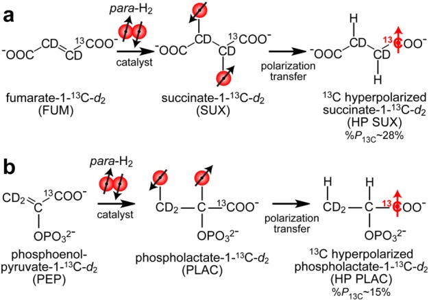
Hyperpolarization of 1-13C-succinate-d2 (SUX) (a) and 1-13C-phospholactate-d2 (PLAC) (b) using parahydrogen induced polarization (PHIP).12,13 1-13C-fumarate-d2 (FUM) and 1-13C-phosphoenolpyruvate-d2 (PEP) molecular precursors undergo catalytic pairwise addition of para-H2 in aqueous medium during continuous-wave (CW) 1H decoupling to yield, respectively, 1H HP products corresponding to the PASADENA regime.14 The 1H polarization of these PASADENA-enhanced protons is then transferred to 13C nucleus using the 3-spin Goldman polarization transfer sequence26 using previously described schemes31,38,55 and known spin–spin couplings.36,55
These additional automated routines were developed for hyperpolarizer cleaning using purging with propellant gas or for performing other basic operations in an automated fashion (Figure 2). Typically, more than 90% para-H2 was used for the experiments described with initially produced ∼98% para-state purity using a previously described para-H2 generator (we note that para-H2 fraction decayed from 98% during storage in a pressurized aluminum cylinder after the initial production step).54
Results and Discussion
13C PHIP of SUX and PLAC
Relatively high levels of 13C polarization were achieved for both HP SUX and HP PLAC: 28% ± 5% and 15% ± 3%,38 respectively (Figure 5). The HP SUX level is approximately a factor of 1.6 greater than the highest polarization level previously reported using a PHIP hyperpolarizer,55 despite an approximately 8 times greater concentration (30 mM vs 3.5 mM).55 This apparent gain in %P13C can be largely attributed to the in situ polarimetry (i.e., detection inside the hyperpolarizer immediately after production) compared to the previous hyperpolarizer design, where 13C polarimetry was carried out after transfer of the material (a process taking ∼10–20 s) from the hyperpolarizer to a high-field NMR detector.41,55 We note that additional optimization of operating parameters (catalyst/PHIP precursor solution preheating delay and reaction time) was required to achieve the best hyperpolarization yields, Figure S7.
Figure 5.
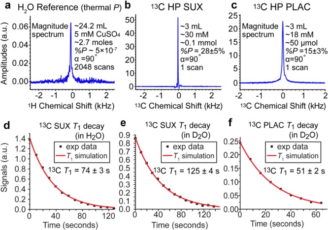
13C and 1H NMR spectroscopy in situ of PHIP hyperpolarizer at 62 kHz resonant frequency. (a) 1H signal reference spectrum recorded using a sample of thermally polarized CuSO4 (∼5 mM) doped water, (b) 13C spectrum of HP SUX, (c) 13C spectrum of HP PLAC, (d) 13C T1 decay of HP SUX in H2O measured using 30° excitation radio frequency (RF) pulses, (e) 13C T1 decay of HP SUX in D2O measured using 30° excitation radio frequency (RF) pulses, and (f) 13C T1 decay of HP PLAC in D2O measured using 30° excitation radio frequency (RF) pulses.
HP PLAC polarization was ∼1.9 times lower than that of HP SUX, which can likely be explained by the effective presence of a four-spin system: two nascent para-H2 protons with 13C and 31P coupled to them in PLAC vs the three-spin system in SUX (two nascent para-H2 protons with coupled 13C). This is supported by two other observations. First, while performance of the hyper-SHIELDED RF pulse sequence (data not shown) was nearly identical to the performance of the Goldman pulse sequence for HP SUX,26 the hyper-SHIELDED sequence56 results yielded an order of magnitude lower %P13C than the Goldman sequence26 (data not shown) for HP PLAC. This is not surprising because the hyper-SHIELDED sequence is specifically geared for robust performance in three-spin systems.56 Second, a theoretical study by Hövener and co-workers57 provided 2D plots of %P13C dependence on the timings of the Goldman polarization transfer sequence (using a three spin formalism),57 which we successfully experimentally reproduced here (Figure S3) for HP SUX. It should be noted that these 2D plots exhibit well-defined local and global maxima and minima of %P13C. The corresponding 2D HP PLAC plots (Figure S3) yielded a pattern without such characteristics indicating that a three-spin formalism is indeed too simplistic. Therefore, %P13C in PLAC can be potentially remedied by more advanced RF pulse sequences potentially including 31P irradiation.
PHIP Hyperpolarizer Compatibility and Potential Improvements
The presented hyperpolarizer is compatible with other HCAs58 produced using RF-based polarization approaches including those already utilized in vivo: diethyl-succinate-13C,32 tetrafluoropropyl propionate,33,34 and HEP.30,43 Other single- or dual-channel RF pulse sequences could be utilized readily including those described earlier.26,27,56,59−61 Moreover, this hyperpolarizer can be tailored to accommodate PHIP using field-cycling-based polarization transfer,5,29 thereby enabling PHIP of other compounds62−64 most notably including acetate-13C29,40 and pyruvate-13C29,39 as well as the production of compounds with long-lived spin states (LLSS65) prepared by pairwise addition of para-H2.66−68
While the hyperpolarizer demonstrated excellent performance from the perspective of automation and robust performance, certain improvements of the current design can be envisioned. In particular, B0 homogeneity can be improved by further magnetic field shimming using additional compensating turns at the ends of the solenoid magnet.69 Moreover, significantly less powerful, smaller, and less expensive RF amplifiers (e.g., ∼5 W70) and NMR spectrometers (e.g., ref (71)) can be employed, because the presented hyperpolarizer design requires ≤2.5 W of RF power per channel. Additional gains in efficiency of RF coils’ performance can be potentially made by increasing the bore size of the magnet (to reduce RF coil coupling to the magnet) and maximize the use of the wire conductor.72
We also note that, while the relatively low magnetic field of the PHIP polarizer (∼5.75 mT) does not offer sufficient chemical shift resolution to differentiate HP metabolites and contrast agents (due to diminished 13C chemical shift dispersion), this is not necessarily a drawback, because high-field NMR detection can be employed by the PHIP hyperpolarizer contrast agents to delineate between metabolite signatures and injected HP contrast agent in vivo, e.g., HP ethyl succinate and its metabolites reported earlier by Bhattacharya and co-workers.32
13C Spectroscopy and Imaging in Small Rodents
The efficient production of HP SUX and HP PLAC using the presented hyperpolarizer enables one to probe in vivo mechanisms and pathways using molecular imaging and spectroscopy. The feasibility of in vivo13C detection was tested for HP SUX at a low magnetic field of 0.0475 T. Figure 6a shows 13C T1 decay of an approximately ∼2 mL bolus of HP SUX (∼30 mM concentration in D2O in a plastic syringe) monitored by 15° excitation pulses using a volume RF probe designed for small animal imaging.72
Figure 6.
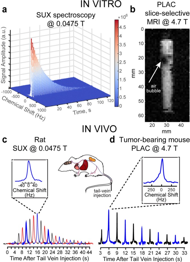
NMR and MRI detection of HP PLAC and SUX in vivo and in vitro. (a) 13C T1 decay of HP SUX (30 mM, D2O, T1 ∼ 125 s) monitored by small-angle RF pulses (α = 15°) at 0.0475 T, (b) selected 2D slice of 13C gradient echo (GRE) image acquired at 4.7 T (raw 2D data shown, image of a 5 mL syringe partially filled with ∼1.5 mL of HP PLAC in D2O was acquired using field of view (FOV) of 64 × 64 mm2, 1 × 1 mm2 pixel size (spatial resolution) and 3 mm slice thickness (note the air bubbles creating dark spots in otherwise uniform approximately expected cylindrical shape)), (c) nonlocalized in vivo13C spectroscopy of a rat conducted after tail-vein injection of HP SUX at 0.0475 T (α = 15°), and (d) nonlocalized in vivo13C spectroscopy of a mouse conducted after tail-vein injection of HP PLAC at 4.7 T (α = 15°).
In a separate experiment, an anesthetized young rat (∼200 g) placed inside a volume RF coil44 was injected with ∼1 mL of HP SUX solution (∼30 mM in H2O) into the tail vein. The effective imaging region of the magnet (∼8 cm long) covered the torso of the rat. 13C spectra were recorded every 2 s using a ∼ 15° excitation RF pulse. The nonlocalized 13C in vivo spectroscopy detected an initial rise of the 13C HP signal followed by its decay due to T1 decay, signal depletion by RF pulses, and metabolic processes. These results demonstrated the feasibility of in vivo13C HP detection using ultra low-field magnetic resonance.
Additional in vivo experiments employed HP PLAC in a nude mouse animal model using a 4.7 T MRI scanner. In the first set of experiments, nonlocalized 13C NMR spectroscopy was performed after injection of ∼0.2 mL of HP PLAC (∼25 mM) via the tail vein (see the Supporting Information for details). The volume RF coil covered the entire mouse body. 13C NMR spectra were acquired every 3 s using ∼15° excitation RF pulses. 13C signal initially increased, because more HP PLAC reached the body of the animal during injection, and it was followed by the decay of HP signal due to T1 decay, signal depletion by RF pulses, and metabolic processes (Figure 6d).
Only one NMR resonance was detected in Figure 6d. Note the in vivo line width at half height (LWHH) of ∼120 Hz or ∼2.5 ppm (Figure 6d, inset), which makes PLAC and lactate (LAC) spectroscopically indistinguishable, because of their small chemical shift difference of ∼0.3 ppm.73 It should be additionally noted that 13C in vivo LWHH is ∼2.5 times smaller (∼40 Hz) than at 4.7 T, clearly demonstrating that low-field MR is far less vulnerable to susceptibility-induced magnetic field gradients (this effect is even more pronounced in the 13C in vitro MRI image of a syringe filled with foamy solution of HP PLAC, where air bubbles create large field gradients resulting in the appearance of low-SNR black spots in the image).
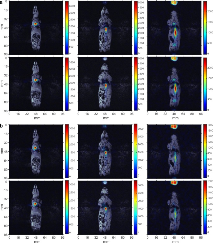
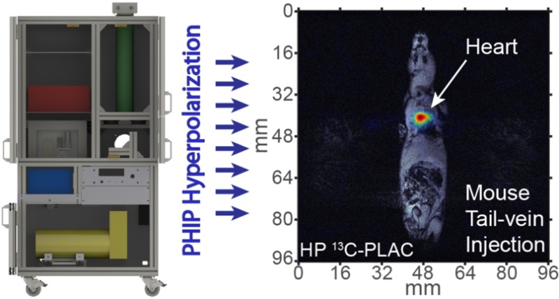
Because direct spectroscopic in vivo differentiation between HP LAC and PLAC was challenging due to LWHH being significantly greater than the chemical shift difference between PLAC and LAC and because only one resonance was seen in Figure 6d, the final in vivo experiments proceeded with performing 13C slice-selective gradient echo (GRE) imaging after PLAC injection in the tail vein of a nude mouse, Figure 7 (see the Supporting Information for details). A series of 6 mm-thick 2D slices was recorded every 4 s with 3 × 3 mm2 in-plane resolution and FOV of 96 × 96 mm2 to probe spatial biodistribution of HP PLAC. 13C HP images were later coregistered with anatomical proton images, Figure 7. Two representative sets of images are shown in Figure 7a,b, respectively. The presence of HCA is seen in the vasculature of the animal, and additional uptake is detected in the heart and in the bladder. This result is consistent with the previous high-resolution NMR biodistribution study of non-HP PLAC,73 which identified that PLAC undergoes dephosphorylation in blood followed by LAC uptake by the heart and other organs with no PLAC signatures found in the heart and other organs. However, the previous study73 lacked the temporal resolution available by HP molecular imaging (Figure 7). On the basis of the in vivo13C images (Figure 7), we conclude that HP PLAC follows the same metabolic fate: (i) it undergoes dephosphorylation in the blood, followed by (ii) exchange with endogenous lactate74 present in tissues and organs. Therefore, injection of HP PLAC results in HP LAC imaging, because HP LAC is produced immediately after HP PLAC injection. As a result, we note the produced HP LAC via PHIP offers a good alternative (to d-DNP HP 13C pyruvate (PYR)) for metabolic imaging, which has already been proven for cardiac applications by comparing the performance of HP LAC and HP PYR metabolism in vivo.75
Figure 7.
In vivo molecular imaging using HP PLAC contrast agent at 4.7 T. 13C gradient echo (GRE) images (in color) are overlaid over representative anatomical 1H proton images. Six coronal 13C images (3 × 3 mm2 in-plane resolution, 6 mm slice thickness, FOV = 96 × 96 mm2) were acquired approximately 5–10 s after injection of HP PLAC via tail vein (∼0.2 mL, ∼30 mM dose) in a nude mouse (prior tumor implantation). Two representative sets of 13C images (a) and (b) separated by ∼4 s are shown and overlaid over the same set of anatomical 1H images.
Serial acquisition of slice-selective 13C HP PLAC images can also be used for HCA washout kinetics analysis. An example of such analysis is shown in Figure S6 based on the pixel-by-pixel analysis of the raw 13C images (Figure S5) in the heart region. It demonstrates that the useful MRI data acquisition time window was ∼12 s using our HCA administration protocol. On the basis of the preliminary feasibility results, future in vivo studies of cancer imaging using HP PLAC injections are certainly warranted given the upregulation of endogenous lactate in many cancers.19,20,23,76
Conclusion
A fully automated open-source low-cost PHIP hyperpolarizer is reported. Sufficient hardware details and operating software are provided for convenient device replication and potential further improvements in the context of PHIP hyperpolarization, as well as potential extensions for other hyperpolarization techniques utilizing para-H2, e.g., conventional NMR signal amplification by reversible exchange (SABRE),77,78 because the main B0 field (∼5.75 mT) of this hyperpolarizer matches the optimal static magnetic field required for coherent polarization transfer by conventional 1H SABRE.79 It should also be noted that this hyperpolarizer design can be potentially tailored for 15N hyperpolarization via recently developed SABRE-SHEATH (SABRE in in SHield Enables Alignment Transfer to Heteronuclei)80−82 in the micro-Tesla magnetic field regime, although the required equipment modifications would likely include the integration of a mu-metal zero field chamber around the main magnet, operation in micro-Tesla versus milli-Tesla regime, and hyperpolarization detection using zero-field NMR.8315N SABRE-SHEATH provides robust hyperpolarization levels of up to 30%84,85 and can be used to hyperpolarize pH sensors,86 hypoxia sensors,84 and Schiff bases87 potentially useful for molecular imaging applications in vivo. The presented PHIP hyperpolarizer enables record levels of polarization for SUX (%P13C = 28% ± 5%) metabolic HCA and enabled efficient (%P13C = 15 ± 3%) hyperpolarization of HP PLAC. The hyperpolarizer can produce a dose of HCA (∼2–3 mL in aqueous medium) as fast as every 3 min. The use of HP SUX was demonstrated for low-field in vivo MR paving the way for future low-field MRI of 13C HCAs. Moreover, the production of HP PLAC enabled the preliminary feasibility study of in vivo spectroscopy and metabolic imaging, demonstrating that HP PLAC likely results in HP LAC after the in vivo dephosphorylation step. The produced HP LAC undergoes in vivo uptake by the heart and bladder clearance consistent with previous studies. We hope the reported PHIP design can be embraced by other laboratories working at the frontiers of molecular in vivo imaging.
Acknowledgments
We thank Dr. Andrew Coy and Dr. John Trail (Magritek, Wellington, New Zealand) for their technical advice and guidance with low-field NMR and MRI hardware, Prof. Kevin W. Waddell for access to the para-H2 generator, and Prof. John C. Gore for institutional support.54 This work was supported by NIH 1R21EB018014, 1R21EB020323, 1F32EB021840, T32 EB001628, and R01 CA160700 (W.P.) and NSF CHE-1416268, DOD CDMRP W81XWH-12-1-0159/BC112431, and W81XWH-15-1-0271.
Supporting Information Available
The Supporting Information is available free of charge on the ACS Publications website at DOI: 10.1021/acs.analchem.6b02130.
The authors declare no competing financial interest.
Supplementary Material
References
- Abragam A.; Goldman M. Rep. Prog. Phys. 1978, 41, 395–467. 10.1088/0034-4885/41/3/002. [DOI] [Google Scholar]
- Carver T. R.; Slichter C. P. Phys. Rev. 1953, 92, 212–213. 10.1103/PhysRev.92.212.2. [DOI] [Google Scholar]
- Theis T.; Ortiz G. X.; Logan A. W. J.; Claytor K. E.; Feng Y.; Huhn W. P.; Blum V.; Malcolmson S. J.; Chekmenev E. Y.; Wang Q.; Warren W. S. Sci. Adv. 2016, 2, e1501438. 10.1126/sciadv.1501438. [DOI] [PMC free article] [PubMed] [Google Scholar]
- Nonaka H.; Hata R.; Doura T.; Nishihara T.; Kumagai K.; Akakabe M.; Tsuda M.; Ichikawa K.; Sando S. Nat. Commun. 2013, 4, 2411. 10.1038/ncomms3411. [DOI] [PMC free article] [PubMed] [Google Scholar]
- Golman K.; Axelsson O.; Johannesson H.; Mansson S.; Olofsson C.; Petersson J. S. Magn. Reson. Med. 2001, 46, 1–5. 10.1002/mrm.1152. [DOI] [PubMed] [Google Scholar]
- Golman K.; in’t Zandt R.; Thaning M. Proc. Natl. Acad. Sci. U. S. A. 2006, 103, 11270–11275. 10.1073/pnas.0601319103. [DOI] [PMC free article] [PubMed] [Google Scholar]
- Kurhanewicz J.; Vigneron D. B.; Brindle K.; Chekmenev E. Y.; Comment A.; Cunningham C. H.; DeBerardinis R. J.; Green G. G.; Leach M. O.; Rajan S. S.; Rizi R. R.; Ross B. D.; Warren W. S.; Malloy C. R. Neoplasia 2011, 13, 81–97. 10.1593/neo.101102. [DOI] [PMC free article] [PubMed] [Google Scholar]
- Comment A.; Merritt M. E. Biochemistry 2014, 53, 7333–7357. 10.1021/bi501225t. [DOI] [PMC free article] [PubMed] [Google Scholar]
- Brindle K. M. J. Am. Chem. Soc. 2015, 137, 6418–6427. 10.1021/jacs.5b03300. [DOI] [PubMed] [Google Scholar]
- Witte C.; Schroder L. NMR Biomed. 2013, 26, 788–802. 10.1002/nbm.2873. [DOI] [PubMed] [Google Scholar]
- Ardenkjaer-Larsen J. H.; Fridlund B.; Gram A.; Hansson G.; Hansson L.; Lerche M. H.; Servin R.; Thaning M.; Golman K. Proc. Natl. Acad. Sci. U. S. A. 2003, 100, 10158–10163. 10.1073/pnas.1733835100. [DOI] [PMC free article] [PubMed] [Google Scholar]
- Eisenschmid T. C.; Kirss R. U.; Deutsch P. P.; Hommeltoft S. I.; Eisenberg R.; Bargon J.; Lawler R. G.; Balch A. L. J. Am. Chem. Soc. 1987, 109, 8089–8091. 10.1021/ja00260a026. [DOI] [Google Scholar]
- Bowers C. R.; Weitekamp D. P. Phys. Rev. Lett. 1986, 57, 2645–2648. 10.1103/PhysRevLett.57.2645. [DOI] [PubMed] [Google Scholar]
- Bowers C. R.; Weitekamp D. P. J. Am. Chem. Soc. 1987, 109, 5541–5542. 10.1021/ja00252a049. [DOI] [Google Scholar]
- Nikolaou P.; Goodson B. M.; Chekmenev E. Y. Chem. - Eur. J. 2015, 21, 3156–3166. 10.1002/chem.201405253. [DOI] [PMC free article] [PubMed] [Google Scholar]
- Jannin S.; Bornet A.; Melzi R.; Bodenhausen G. Chem. Phys. Lett. 2012, 549, 99–102. 10.1016/j.cplett.2012.08.017. [DOI] [Google Scholar]
- Comment A. J. Magn. Reson. 2016, 264, 39–48. 10.1016/j.jmr.2015.12.027. [DOI] [PubMed] [Google Scholar]
- Kurhanewicz J.; Bok R.; Nelson S. J.; Vigneron D. B. J. Nucl. Med. 2008, 49, 341–344. 10.2967/jnumed.107.045112. [DOI] [PMC free article] [PubMed] [Google Scholar]
- Albers M. J.; Bok R.; Chen A. P.; Cunningham C. H.; Zierhut M. L.; Zhang V. Y.; Kohler S. J.; Tropp J.; Hurd R. E.; Yen Y.-F.; Nelson S. J.; Vigneron D. B.; Kurhanewicz J. Cancer Res. 2008, 68, 8607–8615. 10.1158/0008-5472.CAN-08-0749. [DOI] [PMC free article] [PubMed] [Google Scholar]
- Day S. E.; Kettunen M. I.; Gallagher F. A.; Hu D. E.; Lerche M.; Wolber J.; Golman K.; Ardenkjaer-Larsen J. H.; Brindle K. M. Nat. Med. 2007, 13, 1382–1387. 10.1038/nm1650. [DOI] [PubMed] [Google Scholar]
- Gallagher F. A.; Kettunen M. I.; Day S. E.; Hu D. E.; Ardenkjaer-Larsen J. H.; in’t Zandt R.; Jensen P. R.; Karlsson M.; Golman K.; Lerche M. H.; Brindle K. M. Nature 2008, 453, 940–U973. 10.1038/nature07017. [DOI] [PubMed] [Google Scholar]
- Ardenkjaer-Larsen J. H.; Leach A. M.; Clarke N.; Urbahn J.; Anderson D.; Skloss T. W. NMR Biomed. 2011, 24, 927–932. 10.1002/nbm.1682. [DOI] [PubMed] [Google Scholar]
- Nelson S. J.; Kurhanewicz J.; Vigneron D. B.; Larson P. E. Z.; Harzstark A. L.; Ferrone M.; van Criekinge M.; Chang J. W.; Bok R.; Park I.; Reed G.; Carvajal L.; Small E. J.; Munster P.; Weinberg V. K.; Ardenkjaer-Larsen J. H.; Chen A. P.; Hurd R. E.; Odegardstuen L. I.; Robb F. J.; Tropp J.; Murray J. A. Sci. Transl. Med. 2013, 5, 198ra108. 10.1126/scitranslmed.3006070. [DOI] [PMC free article] [PubMed] [Google Scholar]
- Ardenkjaer-Larsen J. H. J. Magn. Reson. 2016, 264, 3–12. 10.1016/j.jmr.2016.01.015. [DOI] [PubMed] [Google Scholar]
- Kumagai K.; Kawashima K.; Akakabe M.; Tsuda M.; Abe T.; Tsuda M. Tetrahedron 2013, 69, 3896–3900. 10.1016/j.tet.2013.03.043. [DOI] [Google Scholar]
- Goldman M.; Johannesson H. C. R. Phys. 2005, 6, 575–581. 10.1016/j.crhy.2005.03.002. [DOI] [Google Scholar]
- Goldman M.; Johannesson H.; Axelsson O.; Karlsson M. Magn. Reson. Imaging 2005, 23, 153–157. 10.1016/j.mri.2004.11.031. [DOI] [PubMed] [Google Scholar]
- Goldman M.; Johannesson H.; Axelsson O.; Karlsson M. C. R. Chim. 2006, 9, 357–363. 10.1016/j.crci.2005.05.010. [DOI] [Google Scholar]
- Reineri F.; Boi T.; Aime S. Nat. Commun. 2015, 6, 5858. 10.1038/ncomms6858. [DOI] [PubMed] [Google Scholar]
- Bhattacharya P.; Harris K.; Lin A. P.; Mansson M.; Norton V. A.; Perman W. H.; Weitekamp D. P.; Ross B. D. MAGMA 2005, 18, 245–256. 10.1007/s10334-005-0007-x. [DOI] [PubMed] [Google Scholar]
- Bhattacharya P.; Chekmenev E. Y.; Perman W. H.; Harris K. C.; Lin A. P.; Norton V. A.; Tan C. T.; Ross B. D.; Weitekamp D. P. J. Magn. Reson. 2007, 186, 150–155. 10.1016/j.jmr.2007.01.017. [DOI] [PMC free article] [PubMed] [Google Scholar]
- Zacharias N. M.; Chan H. R.; Sailasuta N.; Ross B. D.; Bhattacharya P. J. Am. Chem. Soc. 2012, 134, 934–943. 10.1021/ja2040865. [DOI] [PMC free article] [PubMed] [Google Scholar]
- Chekmenev E. Y.; Chow S. K.; Tofan D.; Weitekamp D. P.; Ross B. D.; Bhattacharya P. J. Phys. Chem. B 2008, 112, 6285–6287. 10.1021/jp800646k. [DOI] [PMC free article] [PubMed] [Google Scholar]
- Chekmenev E. Y.; Norton V. A.; Weitekamp D. P.; Bhattacharya P. J. Am. Chem. Soc. 2009, 131, 3164–3165. 10.1021/ja809634u. [DOI] [PMC free article] [PubMed] [Google Scholar]
- Bhattacharya P.; Chekmenev E. Y.; Reynolds W. F.; Wagner S.; Zacharias N.; Chan H. R.; Bünger R.; Ross B. D. NMR Biomed. 2011, 24, 1023–1028. 10.1002/nbm.1717. [DOI] [PMC free article] [PubMed] [Google Scholar]
- Shchepin R. V.; Coffey A. M.; Waddell K. W.; Chekmenev E. Y. J. Am. Chem. Soc. 2012, 134, 3957–3960. 10.1021/ja210639c. [DOI] [PMC free article] [PubMed] [Google Scholar]
- Shchepin R. V.; Chekmenev E. Y. J. Labelled Compd. Radiopharm. 2013, 56, 655–662. 10.1002/jlcr.3082. [DOI] [PMC free article] [PubMed] [Google Scholar]
- Shchepin R. V.; Coffey A. M.; Waddell K. W.; Chekmenev E. Y. Anal. Chem. 2014, 86, 5601–5605. 10.1021/ac500952z. [DOI] [PMC free article] [PubMed] [Google Scholar]
- Cavallari E.; Carrera C.; Boi T.; Aime S.; Reineri F. J. Phys. Chem. B 2015, 119, 10035–10041. 10.1021/acs.jpcb.5b06222. [DOI] [PubMed] [Google Scholar]
- Shchepin R. V.; Barskiy D. A.; Coffey A. M.; Manzanera Esteve I. V.; Chekmenev E. Y. Angew. Chem., Int. Ed. 2016, 55, 6071–6074. 10.1002/anie.201600521. [DOI] [PMC free article] [PubMed] [Google Scholar]
- Hövener J.-B.; Chekmenev E. Y.; Harris K. C.; Perman W.; Tran T.; Ross B. D.; Bhattacharya P. MAGMA 2009, 22, 123–134. 10.1007/s10334-008-0154-y. [DOI] [PMC free article] [PubMed] [Google Scholar]
- Hövener J.-B.; Chekmenev E. Y.; Harris K. C.; Perman W.; Robertson L.; Ross B. D.; Bhattacharya P. MAGMA 2009, 22, 111–121. 10.1007/s10334-008-0155-x. [DOI] [PMC free article] [PubMed] [Google Scholar]
- Waddell K. W.; Coffey A. M.; Chekmenev E. Y. J. Am. Chem. Soc. 2011, 133, 97–101. 10.1021/ja108529m. [DOI] [PMC free article] [PubMed] [Google Scholar]
- Coffey A. M.; Shchepin R. V.; Wilkens K.; Waddell K. W.; Chekmenev E. Y. J. Magn. Reson. 2012, 220, 94–101. 10.1016/j.jmr.2012.04.012. [DOI] [PMC free article] [PubMed] [Google Scholar]
- Agraz J.; Grunfeld A.; Li D.; Cunningham K.; Willey C.; Pozos R.; Wagner S. Rev. Sci. Instrum. 2014, 85, 044705. 10.1063/1.4870797. [DOI] [PubMed] [Google Scholar]
- Kadlecek S.; Vahdat V.; Nakayama T.; Ng D.; Emami K.; Rizi R. NMR Biomed. 2011, 24, 933–942. 10.1002/nbm.1757. [DOI] [PubMed] [Google Scholar]
- Nikolaou P.; Coffey A. M.; Walkup L. L.; Gust B. M.; Whiting N.; Newton H.; Barcus S.; Muradyan I.; Dabaghyan M.; Moroz G. D.; Rosen M.; Patz S.; Barlow M. J.; Chekmenev E. Y.; Goodson B. M. Proc. Natl. Acad. Sci. U. S. A. 2013, 110, 14150–14155. 10.1073/pnas.1306586110. [DOI] [PMC free article] [PubMed] [Google Scholar]
- Nikolaou P.; Coffey A. M.; Walkup L. L.; Gust B. M.; Whiting N. R.; Newton H.; Muradyan I.; Dabaghyan M.; Ranta K.; Moroz G.; Patz S.; Rosen M. S.; Barlow M. J.; Chekmenev E. Y.; Goodson B. M. Magn. Reson. Imaging 2014, 32, 541–550. 10.1016/j.mri.2014.02.002. [DOI] [PMC free article] [PubMed] [Google Scholar]
- Nikolaou P.; Coffey A. M.; Barlow M. J.; Rosen M.; Goodson B. M.; Chekmenev E. Y. Anal. Chem. 2014, 86, 8206–8212. 10.1021/ac501537w. [DOI] [PMC free article] [PubMed] [Google Scholar]
- Nikolaou P.; Coffey A. M.; Ranta K.; Walkup L. L.; Gust B.; Barlow M. J.; Rosen M. S.; Goodson B. M.; Chekmenev E. Y. J. Phys. Chem. B 2014, 118, 4809–4816. 10.1021/jp501493k. [DOI] [PMC free article] [PubMed] [Google Scholar]
- Nikolaou P.; Coffey A. M.; Walkup L. L.; Gust B.; LaPierre C.; Koehnemann E.; Barlow M. J.; Rosen M. S.; Goodson B. M.; Chekmenev E. Y. J. Am. Chem. Soc. 2014, 136, 1636–1642. 10.1021/ja412093d. [DOI] [PMC free article] [PubMed] [Google Scholar]
- Coffey A. M.; Kovtunov K. V.; Barskiy D.; Koptyug I. V.; Shchepin R. V.; Waddell K. W.; He P.; Groome K. A.; Best Q. A.; Shi F.; Goodson B. M.; Chekmenev E. Y. Anal. Chem. 2014, 86, 9042–9049. 10.1021/ac501638p. [DOI] [PMC free article] [PubMed] [Google Scholar]
- Vuichoud B.; Milani J.; Bornet A.; Melzi R.; Jannin S.; Bodenhausen G. J. Phys. Chem. B 2014, 118, 1411–1415. 10.1021/jp4118776. [DOI] [PubMed] [Google Scholar]
- Feng B.; Coffey A. M.; Colon R. D.; Chekmenev E. Y.; Waddell K. W. J. Magn. Reson. 2012, 214, 258–262. 10.1016/j.jmr.2011.11.015. [DOI] [PMC free article] [PubMed] [Google Scholar]
- Chekmenev E. Y.; Hovener J.; Norton V. A.; Harris K.; Batchelder L. S.; Bhattacharya P.; Ross B. D.; Weitekamp D. P. J. Am. Chem. Soc. 2008, 130, 4212–4213. 10.1021/ja7101218. [DOI] [PMC free article] [PubMed] [Google Scholar]
- Cai C.; Coffey A. M.; Shchepin R. V.; Chekmenev E. Y.; Waddell K. W. J. Phys. Chem. B 2013, 117, 1219–1224. 10.1021/jp3089462. [DOI] [PMC free article] [PubMed] [Google Scholar]
- Bär S.; Lange T.; Leibfritz D.; Hennig J.; Elverfeldt D. v.; Hövener J.-B. J. Magn. Reson. 2012, 225, 25–35. 10.1016/j.jmr.2012.08.016. [DOI] [PubMed] [Google Scholar]
- Roth M.; Koch A.; Kindervater P.; Bargon J.; Spiess H. W.; Muennemann K. J. Magn. Reson. 2010, 204, 50–55. 10.1016/j.jmr.2010.01.016. [DOI] [PubMed] [Google Scholar]
- Haake M.; Natterer J.; Bargon J. J. Am. Chem. Soc. 1996, 118, 8688–8691. 10.1021/ja960067f. [DOI] [Google Scholar]
- Kadlecek S.; Emami K.; Ishii M.; Rizi R. J. Magn. Reson. 2010, 205, 9–13. 10.1016/j.jmr.2010.03.004. [DOI] [PMC free article] [PubMed] [Google Scholar]
- Pravdivtsev A. N.; Yurkovskaya A. V.; Lukzen N. N.; Vieth H.-M.; Ivanov K. L. Phys. Chem. Chem. Phys. 2014, 16, 18707–18719. 10.1039/C4CP01445F. [DOI] [PubMed] [Google Scholar]
- Reineri F.; Viale A.; Giovenzana G.; Santelia D.; Dastru W.; Gobetto R.; Aime S. J. Am. Chem. Soc. 2008, 130, 15047–15053. 10.1021/ja8059733. [DOI] [PubMed] [Google Scholar]
- Reineri F.; Viale A.; Ellena S.; Alberti D.; Boi T.; Giovenzana G. B.; Gobetto R.; Premkumar S. S. D.; Aime S. J. Am. Chem. Soc. 2012, 134, 11146–11152. 10.1021/ja209884h. [DOI] [PubMed] [Google Scholar]
- Trantzschel T.; Bernarding J.; Plaumann M.; Lego D.; Gutmann T.; Ratajczyk T.; Dillenberger S.; Buntkowsky G.; Bargon J.; Bommerich U. Phys. Chem. Chem. Phys. 2012, 14, 5601–5604. 10.1039/c2cp40272f. [DOI] [PubMed] [Google Scholar]
- Carravetta M.; Levitt M. H. J. Am. Chem. Soc. 2004, 126, 6228–6229. 10.1021/ja0490931. [DOI] [PubMed] [Google Scholar]
- Kovtunov K. V.; Truong M. L.; Barskiy D. A.; Koptyug I. V.; Coffey A. M.; Waddell K. W.; Chekmenev E. Y. Chem. - Eur. J. 2014, 20, 14629–14632. 10.1002/chem.201405063. [DOI] [PMC free article] [PubMed] [Google Scholar]
- Canet D.; Bouguet-Bonnet S.; Aroulanda C.; Reineri F. J. Am. Chem. Soc. 2007, 129, 1445–1449. 10.1021/ja066313x. [DOI] [PubMed] [Google Scholar]
- Zhang Y. N.; Soon P. C.; Jerschow A.; Canary J. W. Angew. Chem., Int. Ed. 2014, 53, 3396–3399. 10.1002/anie.201310284. [DOI] [PubMed] [Google Scholar]
- Borowiak R.; Schwaderlapp N.; Huethe F.; Lickert T.; Fischer E.; Bär S.; Hennig J.; Elverfeldt D.; Hövener J.-B. MAGMA 2013, 26, 491–499. 10.1007/s10334-013-0366-7. [DOI] [PubMed] [Google Scholar]
- Begus S.; Jazbinsek V.; Pirnat J.; Trontelj Z. J. Magn. Reson. 2014, 247, 22–30. 10.1016/j.jmr.2014.08.002. [DOI] [PubMed] [Google Scholar]
- Michal C. A. Meas. Sci. Technol. 2010, 21, 105902. 10.1088/0957-0233/21/10/105902. [DOI] [Google Scholar]
- Coffey A. M.; Truong M. L.; Chekmenev E. Y. J. Magn. Reson. 2013, 237, 169–174. 10.1016/j.jmr.2013.10.013. [DOI] [PMC free article] [PubMed] [Google Scholar]
- Shchepin R. V.; Pham W.; Chekmenev E. Y. J. Labelled Compd. Radiopharm. 2014, 57, 517–524. 10.1002/jlcr.3207. [DOI] [PMC free article] [PubMed] [Google Scholar]
- Kennedy B. W. C.; Kettunen M. I.; Hu D.-E.; Brindle K. M. J. Am. Chem. Soc. 2012, 134, 4969–4977. 10.1021/ja300222e. [DOI] [PMC free article] [PubMed] [Google Scholar]
- Mayer D.; Yen Y. F.; Josan S.; Park J. M.; Pfefferbaum A.; Hurd R. E.; Spielman D. M. NMR Biomed. 2012, 25, 1119–1124. 10.1002/nbm.2778. [DOI] [PMC free article] [PubMed] [Google Scholar]
- Gatenby R. A.; Gillies R. J. Nat. Rev. Cancer 2004, 4, 891–899. 10.1038/nrc1478. [DOI] [PubMed] [Google Scholar]
- Adams R. W.; Duckett S. B.; Green R. A.; Williamson D. C.; Green G. G. R. J. Chem. Phys. 2009, 131, 194505. 10.1063/1.3254386. [DOI] [PubMed] [Google Scholar]
- Cowley M. J.; Adams R. W.; Atkinson K. D.; Cockett M. C. R.; Duckett S. B.; Green G. G. R.; Lohman J. A. B.; Kerssebaum R.; Kilgour D.; Mewis R. E. J. Am. Chem. Soc. 2011, 133, 6134–6137. 10.1021/ja200299u. [DOI] [PMC free article] [PubMed] [Google Scholar]
- Barskiy D. A.; Kovtunov K. V.; Koptyug I. V.; He P.; Groome K. A.; Best Q. A.; Shi F.; Goodson B. M.; Shchepin R. V.; Truong M. L.; Coffey A. M.; Waddell K. W.; Chekmenev E. Y. ChemPhysChem 2014, 15, 4100–4107. 10.1002/cphc.201402607. [DOI] [PMC free article] [PubMed] [Google Scholar]
- Theis T.; Truong M. L.; Coffey A. M.; Shchepin R. V.; Waddell K. W.; Shi F.; Goodson B. M.; Warren W. S.; Chekmenev E. Y. J. Am. Chem. Soc. 2015, 137, 1404–1407. 10.1021/ja512242d. [DOI] [PMC free article] [PubMed] [Google Scholar]
- Truong M. L.; Theis T.; Coffey A. M.; Shchepin R. V.; Waddell K. W.; Shi F.; Goodson B. M.; Warren W. S.; Chekmenev E. Y. J. Phys. Chem. C 2015, 119, 8786–8797. 10.1021/acs.jpcc.5b01799. [DOI] [PMC free article] [PubMed] [Google Scholar]
- Shchepin R. V.; Truong M. L.; Theis T.; Coffey A. M.; Shi F.; Waddell K. W.; Warren W. S.; Goodson B. M.; Chekmenev E. Y. J. Phys. Chem. Lett. 2015, 6, 1961–1967. 10.1021/acs.jpclett.5b00782. [DOI] [PMC free article] [PubMed] [Google Scholar]
- Theis T.; Ledbetter M. P.; Kervern G.; Blanchard J. W.; Ganssle P. J.; Butler M. C.; Shin H. D.; Budker D.; Pines A. J. Am. Chem. Soc. 2012, 134, 3987–3990. 10.1021/ja2112405. [DOI] [PubMed] [Google Scholar]
- Barskiy D. A.; Shchepin R. V.; Coffey A. M.; Theis T.; Warren W. S.; Goodson B. M.; Chekmenev E. Y. J. Am. Chem. Soc. 2016, 138, 8080–8083. 10.1021/jacs.6b04784. [DOI] [PMC free article] [PubMed] [Google Scholar]
- Shchepin R. V.; Barskiy D. A.; Mikhaylov D. M.; Chekmenev E. Y. Bioconjugate Chem. 2016, 27, 878–882. 10.1021/acs.bioconjchem.6b00148. [DOI] [PMC free article] [PubMed] [Google Scholar]
- Shchepin R. V.; Barskiy D. A.; Coffey A. M.; Theis T.; Shi F.; Warren W. S.; Goodson B. M.; Chekmenev E. Y. ACS Sensors 2016, 1, 640–644. 10.1021/acssensors.6b00231. [DOI] [PMC free article] [PubMed] [Google Scholar]
- Logan A. W. J.; Theis T.; Colell J. F. P.; Warren W. S.; Malcolmson S. J. Chem. - Eur. J. 2016, 22, 10777–10781. 10.1002/chem.201602393. [DOI] [PubMed] [Google Scholar]
Associated Data
This section collects any data citations, data availability statements, or supplementary materials included in this article.


