Significance
Anisotropic electron liquids are ubiquitous in many correlated electron systems. Among them, electron nematics, which break rotation but not translation symmetry, are believed to play a key role in the physics of both cuprates and iron-based superconductors (Fe SC). However the study of electron nematicity has been hampered by the lack of an adequate probe of its associated fluctuations and susceptibility, making it difficult to track its origin. Here, using polarization-resolved Raman scattering, we report the detection of critical nematic fluctuations in the charge channel in the Fe SC compound FeSe. The strong enhancement of the associated nematic susceptibility allows us to link the appearance of nematicity to a symmetry-breaking distortion of the Fermi surface.
Keywords: nematicity, superconductivity, Raman scattering
Abstract
The spontaneous appearance of nematicity, a state of matter that breaks rotation but not translation symmetry, is one of the most intriguing properties of the iron-based superconductors (Fe SC), and has relevance for the cuprates as well. Establishing the critical electronic modes behind nematicity remains a challenge, however, because their associated susceptibilities are not easily accessible by conventional probes. Here, using FeSe as a model system, and symmetry-resolved electronic Raman scattering as a probe, we unravel the presence of critical charge nematic fluctuations near the structural/nematic transition temperature, 90 K. The diverging behavior of the associated nematic susceptibility foretells the presence of a Pomeranchuk instability of the Fermi surface with d-wave symmetry. The excellent scaling between the observed nematic susceptibility and elastic modulus data demonstrates that the structural distortion is driven by this d-wave Pomeranchuk transition. Our results make a strong case for charge-induced nematicity in FeSe.
Electronic nematicity, whereby electrons break rotational symmetry spontaneously, is a ubiquitous property of the iron-based superconductors (Fe SC) (1). As it is often accompanied by magnetic order, an established route to nematicity is via critical magnetic fluctuations (2). However, this mechanism has been questioned in the iron–chalcogenide FeSe, where the nematic transition occurs without magnetic order, indicating a different paradigm for nematicity (3–6).
Despite its simple crystallographic structure, FeSe displays remarkable properties. Its superconducting transition temperature is relatively low at ambient pressure ( 9 K), but it reaches up to 37 K upon application of hydrostatic pressure (7, 8). Its Fermi energy is small (9–12), and in the normal state it shows bad metal behavior (9, 13). Its nematic properties are peculiar as well. The lattice distortion, elastic softening, and elastoresistvity measurements associated with the structural transition at 90 K are comparable with other Fe SC (3, 6, 11), yet NMR and inelastic neutron scattering measurements do not detect sizable low energy spin fluctuations above (4, 6, 14), putting into question the spin nematic scenario envisaged in other Fe SCs (2). Although it has been argued that the magnetic scenario may still apply (15–19), there is growing interest in alternative scenario where charge or orbital degrees of freedom play a more predominant role than spins (5, 11, 20, 21). However, until now direct experimental observation of critical fluctuations associated with electronic charge or orbital nematicity in the tetragonal phase was lacking.
Here, we investigate the nature of nematicity in FeSe by using the unique ability of electronic Raman scattering to selectively probe the dynamics of electronic nematic degrees of freedom without lattice effects (22–27). We unravel the presence of critical charge nematic fluctuations in the tetragonal phase that signals the presence of a d-wave Pomeranchuk instability of the Fermi surface (28). The extracted nematic susceptibility shows quantitative scaling with the measured lattice softening (6, 29), demonstrating that charge nematic fluctuations account entirely for the lattice instability. Our results make a strong case for itinerant electronic charge driven nematicity in FeSe.
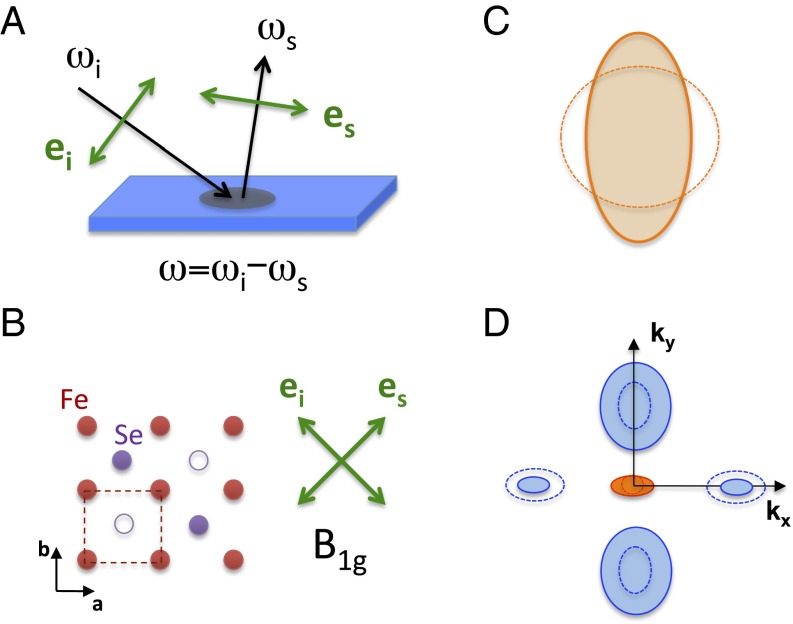
Raman scattering is a photon-in photon-out process, whereby a monochromatic visible light is inelastically scattered at a different frequency by dynamical fluctuations of the electrical polarizability of the sample (Fig. 1A). In metals the Raman spectra at low frequency shifts are typically composed of sharp optical phonon peaks superimposed on a broad electronic background, generally referred to as electronic Raman scattering (ERS). The ERS intensity measures the long wavelength dynamical charge correlation function in the symmetry channel μ: , where ω is the frequency (or Raman) shift between incoming and scattered photons, is the form-factor–weighted electronic charge (30), and † is the Hermitian conjugate. The fluctuation–dissipation theorem in turn links the measured correlation function to the imaginary part of the Raman response function : , where is the Bose function.
Fig. 1.
(A) Schematic of the Raman scattering process with incoming and scattered photons of frequency and polarization , respectively. The Raman shift is defined as the frequency shift between the incoming and scattered photon frequencies. (B) FeSe ab plane with Se atoms alternating above and below the plane defined by the Fe atoms. The 1 Fe unit cell, which neglects the alternating Se atoms, is drawn in dotted lines. In the tetragonal phase above , a = b, and the crystal structure of FeSe has a fourfold symmetry axis. The symmetry is obtained using crossed incoming and scattered photon polarizations at 45 degrees of the Fe–Fe bonds. (C, D) Fermi surface deformation associated to a d-wave Pomeranchuk order for (C) an isotropic Fermi liquid and (D) the multiband Fe SC showing d-wave-like deformations with global symmetry which break the fourfold symmetry axis. The deformations shown are consistent with ARPES measurements in the orthorhombic phase of FeSe (32): and the hole pocket (red) expand along one direction, the elliptical electron pockets (blue) shrink (expand) along the same (other) direction. The 1 Fe unit cell is used.
Because it is a symmetry-resolved probe of the charge fluctuation dynamics with zero momentum transfer, electronic Raman scattering is ideally suited to detect critical in-plane charge nematic fluctuations (22, 23). The symmetry of the charge fluctuations μ probed in a Raman experiment is fixed by the directions of the incoming and scattered photon polarizations. Of interest here is the symmetry (using 1 Fe/cell notation; Fig. 1B), obtained for photons polarized along the diagonals of the Fe–Fe bonds and which transforms as –. The charge nematic fluctuations probed by Raman are equivalent to a Fermi surface deformation with d-wave symmetry. This electronic instability was predicted by Pomeranchuk to occur in an isotropic Fermi liquid in which the Fermi surface spontaneously deforms along a specific direction, breaking rotational symmetry (28) (Fig. 1C). In the context of Fe SC, the Raman response probes the fluctuations associated to a multiband version of a d-wave Pomeranchuk-order parameter that breaks the fourfold symmetry axis (Fig. 1D): where α is the orbital index, a d-wave form factor that transforms as –, and the electron density (25).
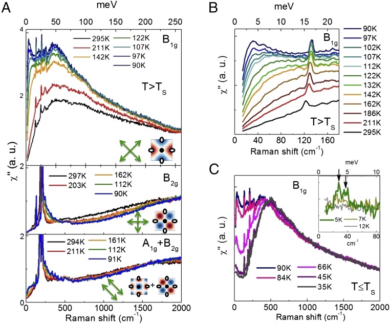
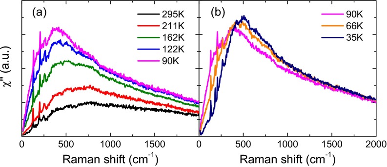
Raman scattering experiments were performed on two different FeSe crystals (SP208 and MK; Supporting Information and refs. 31 and 32). Fig. 2A displays the Raman response in different symmetries μ as a function of temperature in the tetragonal phase () for SP208. For comparison besides the response in symmetry, we also show the response in and symmetries which transform as and + respectively (see form factors in Fig. 2A, Inset). Upon cooling the Raman response displays an overall enhancement over a wide energy range extending up to 2,000 cm−1. At high temperature the response is dominated by a broad peak, centered around 400 cm−1 and the weight of which increases on cooling. In addition, a relatively sharp peak emerges below 100 cm−1: it softens and gains considerably in intensity upon approaching (Fig. 2B). By contrast, the response in the two other configurations is only mildly temperature dependent. The response shows a weak suppression above 500 cm−1 and a build up of spectral weight between 200 and 250 cm−1, which likely originates from an interband transition between nearly parallel spin-orbit split hole bands at the point (11, 33). Below the response strongly reconstructs (Fig. 2C): the low energy response is suppressed and there is a weak transfer of spectral weight at higher energy, above 500 cm−1, in agreement with a previous Raman study (34). Below superconducting gaps open on the different Fermi pockets (Fig. 2C, Inset) giving rise to two sharp peaks at 2 = 28 ( 1) cm−1 ( 3.5 meV) and 37 ( 2) cm−1 ( 4.6 meV), in broad agreement with scanning tunneling microscopy measurements (9).
Fig. 2.
(A) Symmetry-dependent Raman spectra of FeSe (SP208 crystal) above = 87 K using 2.33 eV photons. The sharp peaks superimposed on the electronic continuum are due to Raman active optical phonons. Also shown in Inset are the schematics k-space structures of the Raman form factors in different symmetries (blue and red colors indicate positive and negative amplitudes, respectively), and the polarization configurations used to select them. (B) Temperature dependence of the low energy spectra above . (C) Evolution of the spectra across . The Inset shows the spectra across the superconducting transition at = 8.5 K (SP208). The arrows indicate 2 superconducting peaks.
Focusing on the tetragonal phase, we use the fact that the Raman responses at finite frequency can be translated into their corresponding symmetry-resolved charge susceptibilities at zero frequency using the Kramers–Kronig relation:
| [1] |
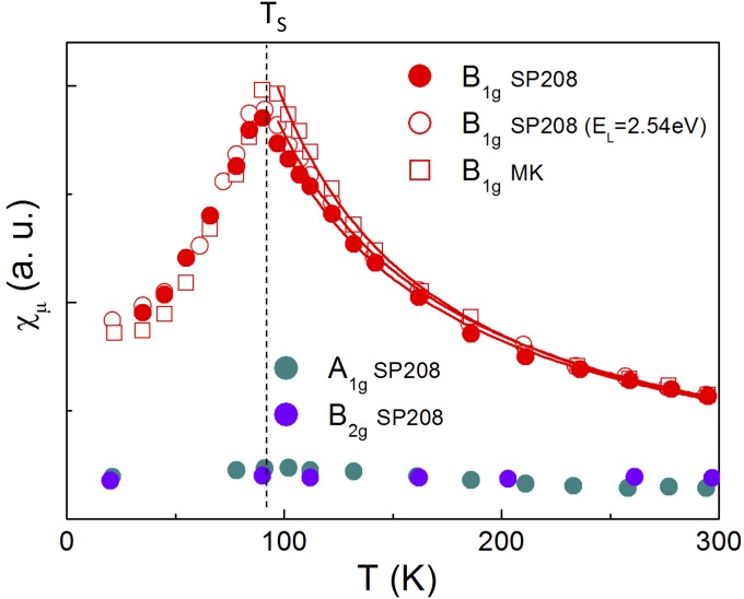
The susceptibilities obtained by integrating the finite frequency responses up to are shown as a function of temperature in Fig. 3. Although the and susceptibilities are nearly T independent, the susceptibility shows a strong enhancement with lowering temperature and subsequently collapses below . This demonstrates the growth of charge nematic fluctuations in the tetragonal phase, which are arrested by the structural transition at . For both SP208 and MK crystals the temperature dependence of above is well captured by a Curie–Weiss law , with a Curie–Weiss temperature significantly below , namely 8 and 20 K for SP208 and MK, respectively.
Fig. 3.
Temperature dependence of the charge nematic susceptibility for SP208 ( = 87 K) and MK ( = 88.5 K) using 2.33 eV photons. Also shown are data on SP208 using a different excitation energy (2.54 eV) and the susceptibility in the other symmetry channels on SP208 ( and ). The lines are Curie–Weiss fits of the susceptibility above .
A key step in the data interpretation is that the nematic fluctuations described above are entirely electronic in origin, and are not affected by the fluctuations of the orthorhombic strain , where is the lattice strain tensor (25). The lattice fluctuations are coupled to the electronic Pomeranchuk order parameter via the electron–phonon interaction , where λ is the coupling constant. The full, measured nematic susceptibility at momentum along the relevant high-symmetry direction and frequency ω can be expressed as
| [2] |
Here is the electronic susceptibility associated with in the absence of the lattice, and the second term is the contribution of the orthorhombic strain with the elastic shear modulus . Crucially, the nematic susceptibility obtained from the finite frequency Raman spectra ( 8 cm−1) using Eq. 1 is in the dynamical limit, i.e., . In this limit the second term of Eq. 2 vanishes, implying that the extracted nematic susceptibility does not couple to the orthorhombic strain fluctuations (24, 25, 35) and, therefore, represents the bare electronic charge nematic transition temperature that is unrenormalized by the lattice. We conclude that the observed Curie–Weiss behavior demonstrates the presence of a d-wave Pomeranchuk instability of purely electronic origin in FeSe. This is in agreement with a recent renormalization group analysis, which shows that the leading instability is in the Pomeranchuk channel in low Fermi energy systems like FeSe (36). The d-wave Pomeranchuk order may explain the peculiar k-dependent orbital splitting observed by angle-resolved photoemission spectroscopy (ARPES) below , which does not fit a simple ferro-orbital order (11, 32, 33).
Having established the presence of critical charge nematic fluctuations, we proceed to show that the structural instability at is entirely driven by the reported charge nematic softening. The renormalization of the relevant shear modulus due to the above-mentioned symmetry-allowed electron–lattice coupling is given by (6, 25)
| [3] |
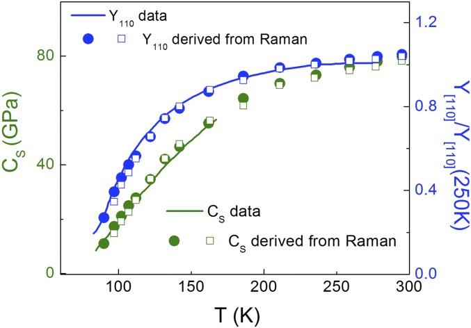
where is the measured charge nematic susceptibility as defined in Eq. 1. We take , the bare modulus, to be T -independent as expected for a purely electronic-driven structural transition thus leaving λ as the only free parameter. As shown in Fig. 4, we find an excellent agreement between the observed softening of , obtained either directly from ultrasound measurements (29), or indirectly from Young’s modulus measurements (6), and obtained from our Raman measurements. Together with the absence of scaling between elastic modulus and spin fluctuations, our result makes a strong case for a lattice distortion in FeSe induced by a d-wave Pomeranchuk instability of the Fermi surface.
Fig. 4.
Shear modulus (29) and Young’s modulus (6) data (line) and corresponding simultaneous fits using the nematic susceptibility extracted from Raman scattering using Eqs. 1 and 3. Full/open symbols correspond to Raman data on SP208/MK crystal. The λ values (in relative units) used for the two crystals agree within 10%. The standard relationship between and was used (6) (see Supporting Information for details).
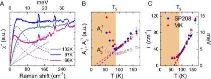
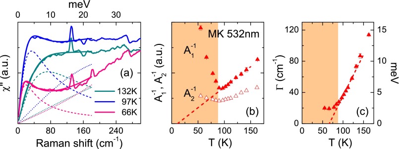
Next, we discuss the frequency dependence of the response in the tetragonal phase. As is evident from the spectra close to in Fig. 2A, the response is composed of two contributions, a sharp quasi-elastic peak (QEP) at low energy (below 200 cm−1), and a much broader peak centered around 400 cm−1. Both features appear only in the symmetry: . The low energy QEP is well reproduced by a damped Lorentzian , which allows a clear separation of the two contributions, and the extraction of the broad close to (Fig. 5A, Supporting Information). As shown in Fig. 5B, their respective contributions and to the nematic susceptibility , through Eq. 1, have different behavior close to in the tetragonal phase. Only the QEP contribution is critical, with extrapolating to zero close to . In contrast, the broad peak contribution , although sizable, increases only mildly upon cooling. In addition, the extracted QEP line width shows a strong softening and extrapolates to zero at 65 K (Fig. 5C).
Fig. 5.
(A) Low energy fits of the response of SP208 using a damped Lorentzian for the QEP and an odd in frequency third-order polynomial for the low energy part of the broad peak (Supporting Information). (B) Temperature dependence of the inverse of the two contributions to the nematic susceptibility, and for SP208 (blue dots) and MK (red triangle). The dashed line is a linear fit of between and 150 K. (C) Temperature dependence of the QEP line width . The dashed line is a linear fit between and 150 K.
In a weak coupling description of a d-wave Pomeranchuk instability, the QEP can be understood as the standard Drude contribution to the Raman conductivity with weight and width that are renormalized by the diverging nematic correlation length ξ (25). Defining , this theory predicts , and , where is a single particle scattering rate. As shown in Fig. 5 B and C, the linear temperature dependencies of and between and 60 K are in agreement with the above expectation. However, the two quantities extrapolate to zero at different temperatures 20 K (± 10 K) and at 65 K (± 5 K) respectively. We attribute this mismatch to a strong linear temperature dependence of the scattering rate , as suggested by resistivity measurements (9, 31) (Supporting Information).
Finally we discuss the microscopic origin of the broad feature. It is unlikely to be from an Azlamazov–Larkin-type contribution of the fluctuations of the stripe magnetic state (24, 27, 37, 38) because, below , inelastic neutron scattering and NMR data suggest an enhancement of low energy spin fluctuations (4, 6, 14), whereas we observe a shift of spectral weight of to higher frequencies. It is also unlikely that the feature is an interband transition, because does not show any gap at low frequencies above (Supporting Information). One possibility is that it is the nematic response of electrons that are not sharply defined quasiparticles. Such an interpretation would be in line with the observed bad metal behavior (9, 13), and the fact that the Fermi energy of FeSe is rather small (9, 11, 12).
Overall, our findings support a scenario in which the nematic transition of FeSe is due to an incipient d-wave Pomeranchuk instability of the Fermi surface. This provides an alternative route to nematicity compared with the prevailing spin fluctuation–mediated scenario that has been proposed for other Fe SC. The subsequent challenge will be to identify the microscopic interaction that is responsible for the Pomeranchuk instability, and to study if such an interaction is relevant for other Fe SC as well.
Materials and Methods
Single crystals of FeSe were grown using the chemical vapor transport method based on the use of an eutectic mixture of AlC3/KCl as described in refs. 9, 31. The two different single crystals measured were grown in Grenoble (SP208) and Kyoto (MK). Polarization-resolved Raman experiments have been carried out using a diode-pumped solid state (DPSS) laser emitting at 2.33 eV. For low energy ( 500 cm−1) measurements, a triple-grating spectrometer equipped with 1,800 grooves/mm gratings and a nitrogen-cooled CCD camera were used. Measurements at higher energies, up to 2,000 cm−1, were performed using a single-grating spectrometer with 600 grooves/mm in combination with an ultrasteep edge filter (Semrock) to block the stray light. Additional measurements were also performed using the 2.54 eV line of an Ar-Kr Laser.
SI Methods
Single crystals of FeSe were grown using chemical vapor transport method based on the use of an eutectic mixture of AlC3/KCl as described in refs. 9, 31. The two different single crystals measured were grown in Grenoble (SP208) and Kyoto (MK). The structural transition temperatures were determined in situ by monitoring the emergence of Rayleigh scattering by orthorhombic domains yielding = 87 K and = 88.5 K for SP208 and MK, respectively (see below for details). These values are in agreement with values extracted from transport measurement (Fig. S9A, refs. 9, 31). The superconducting transition temperatures were measured using SQUID (superconducting quantum interference device) magnetometry giving = 8.5 K (SP208) and = 9.1 K (MK). Again, these values confirm the values extracted from transport measurements (Fig. S9A, refs. 9, 31). The crystals were cleaved and transferred to a close-cycle cryostat in inert atmosphere to prevent surface degradation.
Polarization-resolved Raman experiments have been carried out using a DPSS laser emitting at 2.33 eV. For low energy ( 500 cm−1) measurements, a triple-grating spectrometer equipped with 1,800 grooves/mm gratings and a nitrogen-cooled CCD camera were used. Measurements at higher energies, up to 2,000 cm−1, were performed using a single-grating spectrometer with 600 grooves/mm in combination with an ultrasteep edge filter (Semrock) to block the stray light. Additional measurements were also performed using the 2.54 eV line of an Ar-Kr Laser. The laser spot dimension was 50 × 80 . The typical laser power used was 8 mW, but for spectra in the superconducting state laser power less than 0.2 mW was used. All temperatures were corrected for the estimated laser heating (see below for details).
The and symmetries were obtained using perpendicular incoming and outgoing photon polarizations at 45 degrees, and along of the Fe–Fe bonds, respectively. When using parallel incoming and outgoing photon polarizations at 45 degrees of the Fe–Fe bonds, + symmetries are probed. The component can be isolated from the + spectra by subtracting the contribution obtained independently. A piezorotator was used to change the orientation of the crystal in situ with respect to the photon polarizations. To extract the symmetry-dependent nematic susceptibility from the Raman response at finite frequency using Kramers–Kronig relation, the responses were extrapolated linearly from the lowest frequency measured (8–9 cm−1 depending on the symmetry and sample) to zero frequency.
Laser Heating and Determination of
A clear manifestation of the structural transition is the appearance of Rayleigh scattering at the surface of the crystal due to twin domains formation at . This effect is easy to monitor using a camera to visualize the laser spot during Raman experiments. Moreover, it is very useful to estimate the actual value of , as well as laser heating in situ.
To achieve this, we take pictures of the laser spot at different temperatures for a given value of laser power (Fig. S1), then integrate out the whole spot intensity and plot it as a function of temperature (Fig. S2).
Fig. S1.
Images of the laser spot at different temperatures, taken on an SP208 sample, for a laser power of .
Fig. S2.
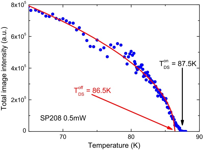
Integrated laser spot image intensity as a function of temperature, for sample SP208, at a laser power of .
Fig. S1 shows images of the laser spot taken at different temperatures on the SP208 sample, for a laser power of . These images show the onset of twin domains scattering at a temperature between and . Because twin domains scattering appears when the effective temperature equals , the onset temperature depends on the value of laser heating.
Fig. S2 shows the temperature dependence of the integrated intensity on SP208 at a laser power of . It shows an order-parameter-like behavior, which extrapolates at a temperature . Note that the integrated intensity starts to be nonzero at a temperature slightly above . This behavior may be due to either the Gaussian tail of the laser spot, for which the actual laser heating is lower than that measured at the center of the laser spot, or to a slightly inhomogeneous distribution of .
The same measurement was also performed for a higher laser power of . The order parameter fit gives . Assuming the following linear relation between the three quantities , , and :
we can thus determine the actual of our sample and the laser heating at transition . We deduce from our two measurements:
The same procedure was applied to sample MK yielding, within error bars, the same estimation of laser heating, but a slightly higher : = 88.5 0.5 K. Knowing these quantities and the temperature dependence of thermal conductivity , we can compute an estimation of laser heating as a function of temperature using the method described in ref. 39.
Comparison with Co-Ba122
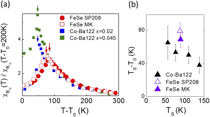
Although there is an apparent contrast between FeSe and other Fe SC with respect to spin degrees of freedom, we show in Fig. S3A that, when plotted as a function of T–, the temperature dependence of the charge nematic susceptibility of FeSe is remarkably similar to the one of electron doped Co-Ba122 (23). However, the two systems differ in the magnitude of the splitting between and , which in a simple Landau-type picture measures the strength of the electron–lattice coupling (40). The splitting is 70–80 K for FeSe, and it is less than 60 K in Co-Ba122 (40 K for undoped Ba122) indicating a larger electron–lattice coupling energy in FeSe (Fig. S3B).
Fig. S3.
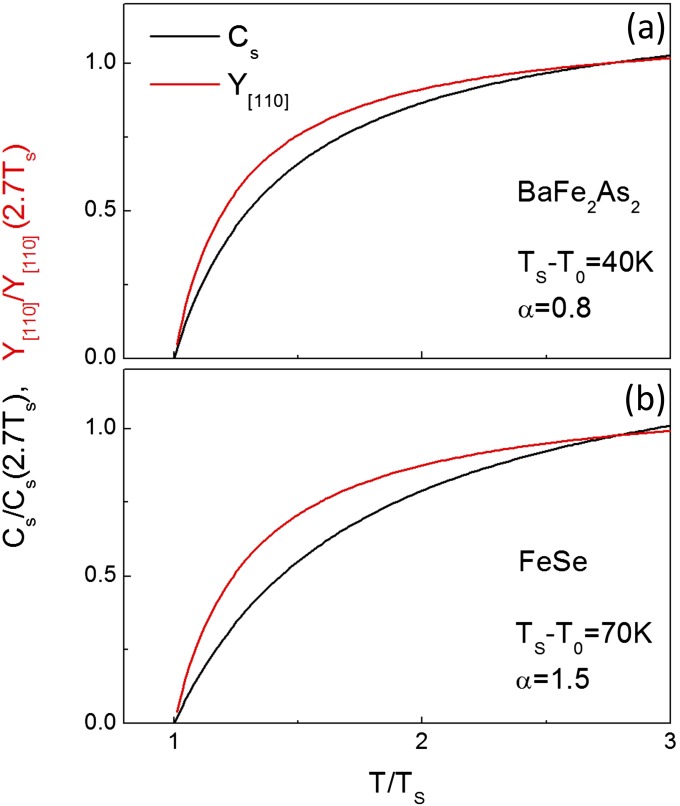
Theoretical Curie–Weiss temperature dependences of and for different values of and α. A corresponds to parameters relevant for BaFe2 As2 and B for FeSe. Values were rescaled at T = 2.7TS.
Link between , , and Nematic Susceptibility
Here we give details on the link between the Raman charge nematic susceptibility, the shear modulus and Young’s modulus along the [110] direction, as measured in 3-point bending measurements (6).
Link between and .
According to elasticity theory can be expressed as a function of the components of the elastic tensor as:
| [S1] |
Using the Voigt notation and the tetragonal (2 Fe) unit cell, the shear modulus is given by =. The coefficient γ depends on four other components: . As in all Fe SC, is the only soft component above . The other components have a weak temperature dependence due to anharmonicity and can be safely approximated as constants between 300 K and (29, 41). Sufficiently close to the behavior of will therefore be dominated by , which strongly softens: . However, this approximation holds only very close , and far away from the proportionality between the two quantities will not be verified. This can be illustrated by assuming that follows a Curie–Weiss dependence as observed in Co-Ba122:
| [S2] |
Here, is the structural transition temperature and can be thought as the electronic nematic transition temperature in the absence of coupling to the lattice. can be identified as the Curie–Weiss temperature extracted from Raman measurements if only charge and lattice degrees of freedom are considered. It is straightforward to compute the corresponding temperature dependence of :
| [S3] |
where and
| [S4] |
The temperature dependence of is still of Curie–Weiss type but with a new characteristic temperature . In the limit where we have . This limit is however never reached in Fe SC where 0.7 in Ba122 and =1.5 in FeSe. In general will be bounded by from below, and from above: . The disagreement between and its estimate from will therefore be marginal when and are close like in Ba122 (about 40 K). However, in FeSe where the difference is more significant, and the full expression [S1] must be used. This is illustrated in Fig. S4 A and B where the normalized temperature dependences of and are plotted for parameters relevant to Ba122 and FeSe, respectively.
Fig. S4.
(A) Comparison between the charge nematic susceptibility of FeSe and Co doped BaFe2 As2 (23) plotted as a function of T– where is the Curie–Weiss temperature of each sample. The arrows indicate the structural transition for each sample. (B) Electron–lattice coupling energy – as a function of for FeSe and Co-Ba122.
Simultaneous Scaling of and with .
The comparison between the experimentally observed softening of and the one expected from the charge nematic susceptibility was performed using Eq. 2 of the main text with =105 (110) GPa for SP208 (MK) sample. The only free parameter was the electron–lattice coupling λ and good agreement was found for each sample in the temperature interval where was measured. The λ value used for SP208 was 10% higher than for MK. Note that because extracted from Raman measurements is only known in relative units, we cannot access the absolute value of λ from the fits. Using the same parameters, and λ, the associated softening of was then computed using Eq. S1 with γ = 70 GPa, as estimated from both elastic constant measurements and ab initio calculations (29, 42). As is only known up to a constant prefactor, the data were rescaled at 250 K (6).
Fits Using a Quasi-Elastic Peak and a Low Energy Background
To quantify the temperature dependences of the two components contributing to nematic fluctuations in FeSe, it is necessary to fit Raman response data, especially the low-energy QEP. To achieve this, we used the following general expression:
| [S5] |
where the QEP is modeled by a damped Lorentzian:
| [S6] |
At low energy the broad peak was modeled using a third-order polynomial form with only odd powers in ω to guarantee causality.
| [S7] |
As is clear from Fig. 4A and Figs. S6A and S7A, Eq. S5 fits well the Raman response data at low energy, up to at least , and at all temperatures, above and below . In particular, below , the high energy peak is partially gapped (see also Fig. S5), resulting in a change in parameter from negative values above to positive values deep below .
Fig. S5.
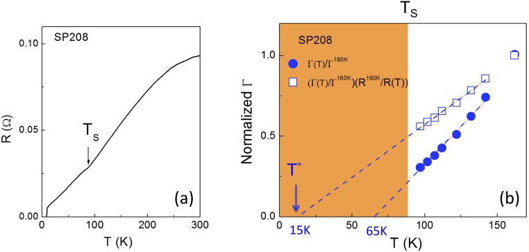
(A) Temperature dependence of the resistance R of FeSe SP208. (B) Temperature dependence of (T) and , normalized at their 160 K values on FeSe SP208.
Fig. S6.
(A) Low energy fits of the response of sample MK at 2.33 eV () using Eq. S5. (B) Temperature dependences of the inverse of the two contributions to the nematic susceptibility, and (red triangles; same as in Fig. 4). The dashed line is a linear fit of between and . It crosses the x axis at . (C) Temperature dependence of the line width of the QEP. The dashed line is a linear fit between and . It crosses the x axis at .
Fig. S7.
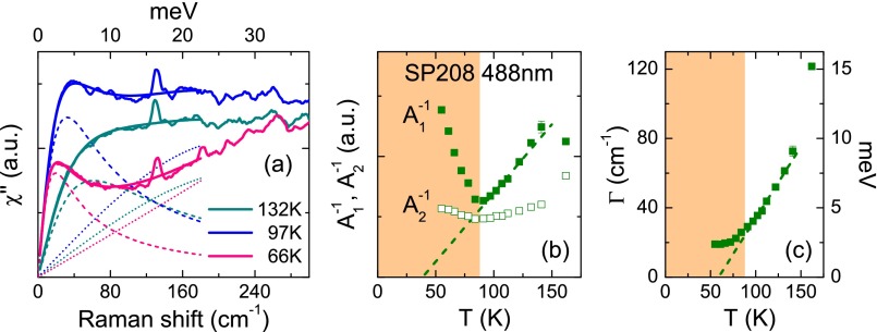
(A) Low energy fits of the response of sample SP208 at 2.54 eV () using Eq. S5. (B) Temperature dependences of the inverse of the two contributions to the nematic susceptibility, and . The dashed line is a linear fit of between and . It crosses the x axis at . (C) Temperature dependence of the line width of the QEP. The dashed line is a linear fit between and . It crosses the x axis at .
Fig. 4B and Figs. S6B and S7B show the temperature dependences of the inverse of the low energy contribution and the high energy contribution to the nematic susceptibility. The quantity at each temperature was extracted from the corresponding fit using Eq. S6. The temperature dependences for all samples were fitted between and using a linear form . The quantity was computed using the following method: the low energy QEP fits were subtracted from the full Raman responses (Fig. S5). The spectra were then divided by frequency and integrated up to .
Fig. 4C and Figs. S6C and S7C show the temperature dependences of the line width of the QEP, directly extracted from fits of the Raman response using Eq. S5. The temperature dependences were fitted between 95 and 150 K using a linear form .
Fits Using Two Quasi-Elastic Peaks
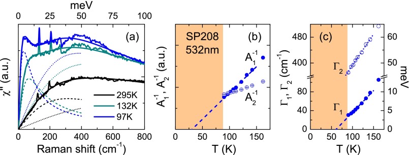
As shown in Fig. S8A, we found that the data can also be well fitted above with a sum of two QEPs, as expected from the contributions of two intraband, Drude-like, terms:
| [S8] |
where
| [S9] |
Fig. S8.
(A) Low energy fits of the response of sample SP208 at 2.33 eV () using Eq. S8. Note that the energy range is wider than that of Fig. 4A and Figs. S6A and S7A. (B) Temperature dependences of the inverse of the two contributions to the nematic susceptibility, and . The dashed line is a linear fit of between and . It crosses the x axis at . (C) Temperature dependences of the line widths and of the low and high energy QEPs, respectively. The dashed and dotted lines are linear fits between and . The dashed line crosses the x axis at .
Fits using Eq. S8 are good up to 1,000 cm−1, strengthening our interpretation that the brand peak arises from more incoherent intraband excitations. Note however, that because of the partial gapping mentioned above, the two QEP analysis does not reproduce the data satisfactorily below . Fig. S8B shows the temperature dependences of the inverse of the two contributions to the nematic susceptibility, and extracted from the fits. Fig. S8C shows the temperature dependences of the line widths and of QEP1 and QEP2, respectively. Both quantities show linear temperature dependences, indicated by dashed and dotted lines, respectively.
QEP Line Width and Resistivity
In a random phase approximation picture of a d-wave Pomeranchuk transition we expect the QEP amplitude to scale as . Here, , where is the nematic correlation length and the mean-field nematic transition temperature (25). Experimentally , the zero temperature intercept of ( 25 K ( 15 K)), is indeed close to , as obtained from the global Curie–Weiss fit of . However, the zero temperature intercept of the QEP line width , , is significantly higher: 65 K ( 5 K).
Here we show that the shift between and can be accounted by the temperature dependence of the bare quasiparticle scattering as measured by e.g., transport. In FeSe, and in contrast to e.g., BaFe2 As2, the resistivity is strongly temperature dependent above . Between and 200 K it show quasi-linear behavior with a positive intercept on the temperature axis. Because (T) , the temperature dependence of the QEP line width will contain contributions coming from both the quasiparticle scattering rate and .
Assuming that is proportional to the resistivity, , we can extract the temperature dependence of (T) by dividing the measurement of QEP line width by the resistance R:
| [S10] |
We have used the resistivity data on a crystal from the same batch as SP208 (Fig. S9) to correct the temperature dependence of (T). (T) and , normalized at their 160 K values, are shown in Fig. S9B. Although the temperature dependence of (T) between and 150 K extrapolates linearly at 65 K, the quantity extrapolates at a lower temperature 15 K, now much closer to the value of extracted from the temperature dependence of QEP amplitude . Taking into account the temperature dependence of the scattering rate thus reconciles the temperature dependences of (T) and (T).
Fig. S9.
High energy contribution to the Raman response, with the low energy QEP component subtracted, of sample SP208 at 2.33 eV () as a function of temperature (A) above and (B) below .
Acknowledgments
We thank G. Blumberg, V. Brouet, A. V. Chubukov, V. D. Fil, R. Hackl, and J. Schmalian for fruitful discussions. P.M., M.-A.M., M.C., A.S., and Y.G. acknowledge financial support from ANR Grant “Pnictides,” from a Labex SEAM grant, and from a SESAME grant from région Ile-de-France. P.T. and S. Karlsson acknowledge the financial support of UJF (now integrated inside “Université Grenoble Alpes”) and Grenoble INP (through the AGIR-2013 contract of S. Karlsson). S. Kasahara., T.S., and Y.M. acknowledge the support of Grants-in-Aid for Scientific Research (KAKENHI) from Japan Society for the Promotion of Science (JSPS), and the Topological Quantum Phenomena (25103713) Grant-in-Aid for Scientific Research on Innovative Areas from the Ministry of Education, Culture, Sports, Science and Technology (MEXT) of Japan.
Footnotes
The authors declare no conflict of interest.
This article is a PNAS Direct Submission.
This article contains supporting information online at www.pnas.org/lookup/suppl/doi:10.1073/pnas.1606562113/-/DCSupplemental.
References
- 1.Chu J-H, et al. In-plane resistivity anisotropy in an underdoped iron arsenide superconductor. Science. 2010;329(5993):824–826. doi: 10.1126/science.1190482. [DOI] [PubMed] [Google Scholar]
- 2.Fernandes RM, Chubukov AV, Schmalian J. What drives nematic order in iron-based superconductors? Nat Phys. 2014;10:97–104. [Google Scholar]
- 3.McQueen TM, et al. Tetragonal-to-orthorhombic structural phase transition at 90 K in the superconductor Fe(1.01)Se.1.01. Phys Rev Lett. 2009;103(5):057002. doi: 10.1103/PhysRevLett.103.057002. [DOI] [PubMed] [Google Scholar]
- 4.Imai T, Ahilan K, Ning FL, McQueen TM, Cava RJ. Why does undoped FeSe become a high-Tc superconductor under pressure? Phys Rev Lett. 2009;102(17):177005. doi: 10.1103/PhysRevLett.102.177005. [DOI] [PubMed] [Google Scholar]
- 5.Baek S-H, et al. Orbital-driven nematicity in FeSe. Nat Mater. 2015;14(2):210–214. doi: 10.1038/nmat4138. [DOI] [PubMed] [Google Scholar]
- 6.Böhmer AE, et al. Origin of the tetragonal-to-orthorhombic phase transition in FeSe: A combined thermodynamic and NMR study of nematicity. Phys Rev Lett. 2015;114(2):027001. doi: 10.1103/PhysRevLett.114.027001. [DOI] [PubMed] [Google Scholar]
- 7.Medvedev S, et al. Electronic and magnetic phase diagram of β-Fe(1.01)Se with superconductivity at 36.7 K under pressure.1.01. Nat Mater. 2009;8(8):630–633. doi: 10.1038/nmat2491. [DOI] [PubMed] [Google Scholar]
- 8.Garbarino G, et al. High-temperature superconductivity (Tc onset at 34 K) in the high-pressure orthorhombic phase of FeSe. EPL. 2009;86:27001. [Google Scholar]
- 9.Kasahara S, et al. Field-induced superconducting phase of FeSe in the BCS-BEC cross-over. Proc Natl Acad Sci USA. 2014;111(46):16309–16313. doi: 10.1073/pnas.1413477111. [DOI] [PMC free article] [PubMed] [Google Scholar]
- 10.Terashima T, et al. Anomalous Fermi surface in FeSe seen by Shubnikov-de Haas oscillation measurements. Phys Rev B. 2014;90:144517. doi: 10.1103/PhysRevLett.107.176402. [DOI] [PubMed] [Google Scholar]
- 11.Watson MD, et al. Emergence of the nematic electronic state in FeSe. Phys Rev B. 2015;91:155106. [Google Scholar]
- 12.Audouard A, et al. Quantum oscillations and upper critical magnetic field of the iron-based superconductor FeSe. EPL. 2015;109:27003. [Google Scholar]
- 13.Aichhorn M, Biermann S, Miyake T, Georges A, Imada M. Theoretical evidence for strong correlations and incoherent metallic state in FeSe. Phys Rev B. 2010;82:064504. [Google Scholar]
- 14.Wang Q, et al. Strong interplay between stripe spin fluctuations, nematicity and superconductivity in FeSe. Nat Mater. 2016;15(2):159–163. doi: 10.1038/nmat4492. [DOI] [PubMed] [Google Scholar]
- 15.Glasbrenner JK, et al. Effect of magnetic frustration on nematicity and superconductivity in iron chalcogenides. Nat Phys. 2015;11:953–957. [Google Scholar]
- 16.Wang F, Kivelson S, Lee D-H. Nematicity and quantum paramagnetism in FeSe. Nat Phys. 2015;11:959–963. [Google Scholar]
- 17.Chubukov AV, Fernandes RM, Schmalian J. Origin of nematic order in FeSe. Phys Rev B. 2015;91:201105. [Google Scholar]
- 18.Yu R, Si Q. Antiferroquadrupolar and Ising-nematic orders of a frustrated bilinear-biquadratic Heisenberg model and implications for the magnetism of FeSe. Phys Rev Lett. 2015;115(11):116401. doi: 10.1103/PhysRevLett.115.116401. [DOI] [PubMed] [Google Scholar]
- 19.Yamakawa Y, Omari S, Kontani H. Nematicity and magnetism in FeSe and other families of Fe-based superconductors. Phys Rev X. 2016;6:021032. [Google Scholar]
- 20.Jiang K, Hu J-P, Ding H, Wang Z. Interatomic Coulomb interaction and electron nematic bond order in FeSe. Phys Rev B. 2016;93:115138. [Google Scholar]
- 21.Su Y, Liao H, Li T. The form and origin of orbital ordering in the electronic nematic phase of iron-based superconductors. J Phys Condens Matter. 2015;27(10):105702. doi: 10.1088/0953-8984/27/10/105702. [DOI] [PubMed] [Google Scholar]
- 22.Yamase H, Zeyher R. Electronic Raman scattering from orbital nematic fluctuations. Phys Rev B. 2013;88:125120. [Google Scholar]
- 23.Gallais Y, et al. Observation of incipient charge nematicity in Ba(Fe(1-x)Co(x))2As2. Phys Rev Lett. 2013;111(26):267001. doi: 10.1103/PhysRevLett.111.267001. [DOI] [PubMed] [Google Scholar]
- 24.Kontani H, Yamakawa Y. Linear response theory for shear modulus C66 and Raman quadrupole susceptibility: Evidence for nematic orbital fluctuations in Fe-based superconductors. Phys Rev Lett. 2014;113(4):047001. doi: 10.1103/PhysRevLett.113.047001. [DOI] [PubMed] [Google Scholar]
- 25.Gallais Y, Paul I. Charge nematicity and electronic Raman scattering in iron-based superconductors. C R Phys. 2016;17:113–139. [Google Scholar]
- 26.Thorsmølle VK, et al. Critical charge fluctuations in iron pnictide superconductors. Phys Rev B. 2016;93:054515. [Google Scholar]
- 27.Kretzschmar F, et al. Critical spin fluctuations and the origin of nematic order in Ba(Fe1-xCox)2As2. Nat Phys. 2016;12:560–563. [Google Scholar]
- 28.Pomeranchuk IJ. On the stability of a Fermi liquid. Sov Phys JETP. 1958;8:361. [Google Scholar]
- 29.Zvyagina GA, et al. Acoustic characteristics of FeSe single crystals. EPL. 2013;101:56005. [Google Scholar]
- 30.Devereaux TP, Hackl R. Inelastic light scattering from correlated electrons. Rev Mod Phys. 2007;79:175. [Google Scholar]
- 31.Karlsson S, et al. Study of high-quality superconducting FeSe single crystals: Crossover in electronic transport from a metallic to an activated regime above 350 K. Supercond Sci Technol. 2015;28:105009. [Google Scholar]
- 32.Suzuki Y, et al. Momentum-dependent sign-inversion of orbital polarization in superconducting FeSe. Phys Rev B. 2015;92:205117. [Google Scholar]
- 33.Zhang P, et al. Observation of two distinct dxz=dyz band splittings in FeSe. Phys Rev B. 2015;91:214503. [Google Scholar]
- 34.Gnezdilov V, et al. Interplay between lattice and spin states degree of freedom in the FeSe superconductor: Dynamic spin state instabilities. Phys Rev B. 2013;87:144508. [Google Scholar]
- 35.Gallais Y, Paul I, Chauvière L, Schmalian J. Nematic resonance in the Raman spectrum of iron-based superconductors. Phys Rev Lett. 2016;116(1):017001. doi: 10.1103/PhysRevLett.116.017001. [DOI] [PubMed] [Google Scholar]
- 36.Chubukov AV, Khodas M, Fernandes RM. 2016. Magnetism, superconductivity, and spontaneous orbital order in iron-based superconductors: Who comes first and why? arXiv:1602.05503.
- 37.Khodas M, Levchenko A. Raman scattering as a probe of nematic correlations. Phys Rev B. 2015;91:235119. [Google Scholar]
- 38.Karahasanovic U, et al. Manifestation of nematic degrees of freedom in the Raman response function of iron pnictides. Phys Rev B. 2015;92:075134. [Google Scholar]
- 39.Maksimov AA, et al. Investigations of the temperature dependence of the low energy electronic Raman scattering in Ti2Ba2CaCu2O8 single crystals. Solid State Commun. 1992;81:407. [Google Scholar]
- 40.Yoshizawa M, et al. Structural quantum criticality and superconductivity in iron-based superconductor Ba(Fe1 xCox)2As2. J Phys Soc Jpn. 2012;81:024604. [Google Scholar]
- 41.Simayi S, et al. 2013. Strange inter-layer properties of Ba(Fe1-xCox)2As2 appearing in ultrasonic measurements. arXiv:1310.2681.
- 42.Chandra S, Islam AKMA. Elastic properties of mono- and poly-crystalline PbO-type FeSe1-xTex (x = 0-1.0): A first-principles study. Physica C. 2010;470:2072. [Google Scholar]


