Abstract
The design, fabrication and test of a microfluidic cell trapping device to measure single cell exocytosis were reported. Research on the patterning of double layer template based on repetitive standard photolithography of AZ photoresist was investigated. The replicated poly(dimethyl siloxane) devices with 2.5 μm deep channels were proved to be efficient for stopping cells. Quantal exocytosis measurement can be achieved by targeting single or small clumps of chromaffin cells on top of the 10 μm ×10 μm indium tin oxide microelectrodes arrays with the developed microdevice. And about 72% of the trapping sites can be occupied by cells with hydrodynamic trapping method and the recorded amperometric signals are comparable to the results with traditional carbon fiber microelectrodes. The method of manufacturing the microdevices is simple, low-cost and easy to perform. The manufactured device offers a platform for the high throughput detection of quantal catecholamine exocytosis from chromaffin cells with sufficient sensitivity and broad application.
Introduction
The release of transmitter molecules packed in membrane-bound vesicles to the extracellular environment through a process called exocytosis is the key dynamic event in cell-to-cell communication. Disordered exocytosis is involved in several neurological disorders such as Parkinsons and Alzheimers diseases.1
Measurement of transmitter release from living cells has always been an area of great interest in biological and medical science as the study of single cell dynamics could help us better understands diverse processes such as exocytotic pathway, vesicle fusion dynamics and presynaptic regulation of neurotransmission, etc. To obtain fast, sensitive, spatially resolved analysis of exocytosis, robust and reliable cellular analysis systems are required. Several well-established techniques, including patch-clamp capacitance detection,2 optical spectroscopy,3 and electrochemical sensing with ultramicroelectrodes,4 have been employed to investigate these events. Despite of excellent time resolution of vesicle fusion event provided by the state-of-the-art techniques, these techniques are, to a certain extent, labor intensive and low-throughput, because they require highly skilled lab technicians for the manual positioning of the electrode to the cell surface using micromanipulators, and only one cell can be detected at a time. In addition, the glass pipette and carbon fiber electrodes are manually fabricated individually or in small lots.
With increasing development of lab-on-a-chip systems, novel applications of chip-based microfluidics in addressing fundamental biological questions and developing innovative cell and biochemical assays has been explored. Microsystems designed to achieve parallel recordings from single cells and multiple cells were reviewed recently.5, 6 Notably, electrochemical method is the most frequently utilized due to the ease of integration. They have been designed based on microelectrodes arrays7 or microelectrodes integrated in microchannels8, 9 or microwells10, 11 to measure the catecholamine release.
Electrophysiological measurement based on the planar aperture was also reported, among them, it is worth mentioning that some of these microdevices were also designed to allow coupling between amperometry and electrophysiological or optical measurements of exocytosis. Amatore measured the exocytosis of single vesicles with amperometry and total internal reflection fluorescence microscopy.12, 13 A microfluidic device coupled with functionalities of fluorescence imaging and amperometric detection has been developed to enable the real-time monitoring of the exocytotic events of single SHSY5Y neuroblastoma cells.14 Sigworth’s group at Yale fabricated poly(dimethyl siloxane) (PDMS) substrates to replace the pipette and successfully recorded single ion channel current from Xenopus oocytes.15 Fertig and colleagues reported a planar patch-clamp glass chip to record electrical current measure from different cell types in a whole-cell mode.16 In order to achieve the goal of quantal release measurement, an efficient cell trapping device integrated with microelectrodes are of crucial importance. We have manufactured a microfluidic system with poly-L-lysine coated indium tin oxide (ITO) electrode for the detection of quantal exocytosis from small assemblies of chromaffin cells,8 but high sensitivity electrochemical detection is difficult to achieve since cells are randomly scattered on comparatively larger electrodes. Huang et al.17 have developed a microfluidic system for the hydrodynamic transfer of a cell to a micromanipulator controlled carbon fiber microelectrode (CFME), but the experimental process is tedious and time consuming. Dittami and Rabbitt9 trapped cells over an electrode using a constriction in a microfluidic channel, but the fabrcrication of the electrodes and cell manipulation device requires specialized equipment.
Due to the small size and delicate feature of cells, single cell trapping design takes extra caution in terms of trapping structure fabrication, electrode integration and driving force application. As we know that for single cell analysis, usually one cell is positioned to one electrode within one trapping spot, therefore, the fabrication work requires expensive facility, which in turn increases the cost of a robust microdevice and limits its application. For example, single PC12 cells were precisely positioned to a sensing gold ring electrode with an about 3 μm aperture similar to patch-clamping. The aperture fabrication, electrode integration and insulation were all involved with complicated microfabrication equipment which may not be available in many labs.18 Moreover, automatic and high-throughput analysis of the cell exocytosis by microfluidic technologies is an important step to speed the drug discovery process. The excellent precision and accuracy of single cell exocytosis measurements is limited by the cell variability and solution handling equipment. And, measurement at single cell level becomes meaningful only when enough individual experiments can be performed with different cell batches. Thus, precise analytical measurements after or in conjunction with a series of cell manipulations and exposition to chemical or biochemical reagents is needed. The multilayer soft lithography has greatly promoted the use of mechanically controlled microflows and the displacement of cells into microfluidic devices.19, 20 These devices have been used to perform a variety of investigations concerning cell analysis, owing to advantages such as miniaturization, multiple function integration, low reagent consumption, fast analysis and high detection sensitivity.21, 22
In our work, a new method of patterning two-layer AZ positive was developed based on standard photolithography, and elastomeric PDMS substrates were casted to fabricate flexible two-layer microfluidic devices. By heating the first layer of patterned positive photoresist to 200°C, a second layer of AZ photoresist can be spin-coated, exposed and developed without destroying the existing structures. The fabricated device was applied to trap single or a small number of cells, indium tin oxide (ITO) microelectrodes with sizes as small as 10 μm×10 μm was tested as the sensing electrodes to measure exocytosis from the localized cells. By utilizing the cell trapping devices, cells can be automatically trapped at the entrance of the shallow microfluidic channels at mild hydraulic pressure, while the cell debris was allowed to pass through and exit to the waste reservoir, and high throughput assay of single cell exocytosis can be achieved. Even though AZ photoresist was widely used in microfabrication, but direct patterning of two-layer photoresist was fewly reported. The method of multilayer patterning of the AZ photoresist in our work was proved to be simple and cost effective compared with other multilayer fabrication techniques, such as laser ablation, reactive ion etching, etc., and it can cut the operating cost of clean room equipment, simplify the three dimensional fabrication procedure and facilitate many complicated biomedical device fabrication. Compared with the reported method for single cell secretion measurement, this soft-lithography based cell trapping device can be used as an alternative with comparatively low cost and easy operation.
Materials and methods
Template fabrication
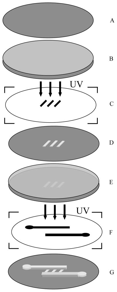
Multiple coating AZ photoresist on the silicon wafer to increase the film thickness is recommended as in the data sheet, but multiple photolithographic processing AZ photoresist to get a multilayer structure is fewly reported. In our work, a two-layer photoresist was patterned by double photolithography on a 3 inch silicon wafer. The first layer was patterned by diluting AZ 4600 photoresist (Clariant Electronic Materials, Somerville, NJ, USA) with propylene glycol monomethyl ether acetate at a ratio of 4:1 (photoresist:solvent), and spin-coating on a silicon wafer at ~3000 rpm (Fig 1B). After baking at 100 °C for 1 min on a hot plate, the wafer was next exposed to UV light using a high-resolution transparency film as a photomask. The photoresist was then developed in the recommended developer solution and post-baked at 200 °C for 1 hour to harden the photoresist (Fig. 1D). The fabricated shallow channels (2–15 μm in depth) were used as the cell trapping structure. A second layer of AZ 4600 photoresist was spin-coated onto the patterned silicon wafer (Fig. 1E), after 2 min baking at 100 °C, the photoresist was exposed to UV after alignment with another transparency film. A home-built vacuum system worked as mask aligner, where transparency film can stick to a PDMS slab which sucked up by vacuum and controlled by a three-dimensional coarse manipulator. By adjusting the manipulator, the transparency film can move above the silicon wafer under an upright microscope with a 20 cm working distance lense (Olympus, BX-50WI). Following the developing and hard-baking process, a 20 μm wide inlet channel and an 40 μm outlet channel with 20 μm thickness connected a series of shallow channels were fabricated (Fig. 1G).
Fig. 1.
(A) Silicon wafer, (B) Silicon wafer coated with the first layer of AZ photoresist, (C) Transparency film with shallow channel features, (D) AZ photorisist template with patterned shallow channels, (E) template with spin-coated second layer of phototesist, (F) Transparency film with inlet and outlet channels, (G) Two-layer AZ photoresist template
Electrode fabrication
Indium tin oxide (In2O3/SnO2)-coated glass slides (75 mm × 25 mm × 1 mm, film thickness ~150–300 A°) with a resistance of 70–100 Ω/square were obtained from Sigma (St. Louis, MO). The ITO microelectrodes were patterned into 10 μm wide stripes terminating in 1 by 1 mm squares at the edge of the slide to allow connection to an amplifier following a photolithographic and wet-etching procedure as we used previously.8 The microelectrode arrays were insulated by SU-8 photoresist following the standard photolithography procedures. A thickness of ~0.5 μm SU-8 2000 (MicroChem Corp., USA) was patterned on ITO microelectrodes arrays, leading to a 10 μm thin opening vertical to the electrode strips, hence arrays of 10 μm by 10 μm microelectrodes were fabricated as the sensing electrodes as in Fig. 2A.
Fig. 2.
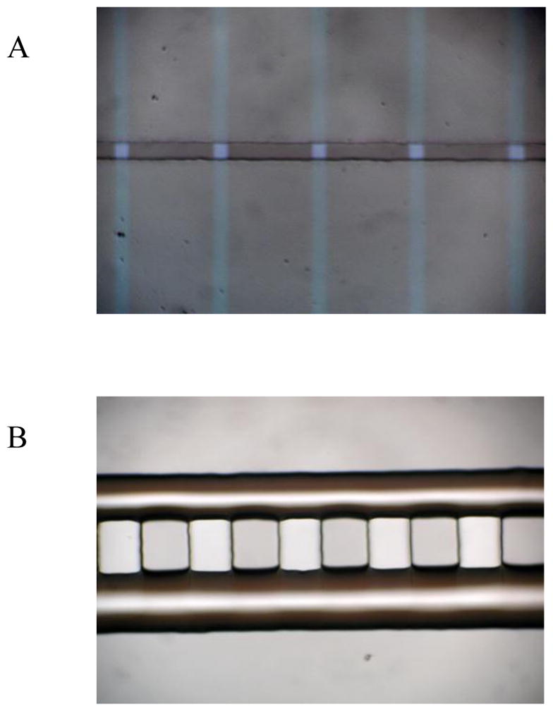
(A) ITO microelectrodes arrays, (B) the PDMS cell trapping device.
Cell preparation and solutions
Bovine adrenal chromaffin cells were prepared as described before [8]. About 105 cells in 3 mL of culture media (Dulbecco’s modified Eagles medium supplemented with 10% (v/v) fetal bovine serum and 1% penicillin/streptomycin) were seeded onto a 30-mm polystyrene culture dish. Cells were kept in a 37 °C incubator in a humidified environment with 5% CO2 and used 1–3 days after preparation. The standard bath solution for experiments consisted of 150 mM NaCl, 5 mM KCl, 5 mM CaCl2, 2 mM MgCl2, 10 mM glucose and 10 mM HEPES titrated to pH 7.2 with NaOH. The “high-K+” solution used to stimulate exocytosis consisted of 55 mM NaCl, 100 mM KCl, 5 mM CaCl2, 2 mM MgCl2, 10 mM HEPES, and 10 mM glucose. All reagents were obtained from Sigma, unless otherwise stated. Immediately before use, cells were dissociated from the 30-mm dish using a vigorous wash with the standard bath solution to give a density of 104 cells/mL.
Assembly of the microchip
PDMS cell trapping device (Fig. 2B) was casted by mixing Sylgard 184 polymer to crosslinker at a ratio of 20:1 (Dow Corning, USA) and cured overnight at room temperature. The PDMS substrates prepared at the above condition is elastic and a reversible sealing to the SU-8 film is easy to achieve. The Ag/AgCl reference electrode and Pt counter electrode were placed at the waste reservoir. Cyclic voltammetry and constant potential amperometry studies were performed using an EPC-9 patch-clamp amplifier (HEKA, Lambrecht, Germany) and PULSE software (HEKA). Cells and electrodes were observed under an inverted microscope (Nikon TMS, Japan) and an upright microscope (Olympus, BX-50WI, Japan). The analysis of spike widths and areas was performed using Igor software (Wavemetrics, USA).
Results and disccusion
Characterization and integration of ITO microelectrodes arrays
Precise amperometric measurements requires electrode surface areas small enough to minimize non-faradic information such as electrical noise and capacitive currents, because larger electrodes cannot ensure all the quantal release events be detected due to the high background noise, although, electrodes need to remain large enough for allowing a quantitative collection of released molecules from releasing point distributed on the surface of a single cell or from a collection of cells depending on the scope of the measurements. In our work, a compromise between these conflicting requirements can be provided by using ITO planar microelectrodes with sizes of 10 μm by10 μm. The small size of the electrodes has two advantages: first, it simplified the alignment of the 20 μm wide PDMS channel to the 10 μm wide electrodes. Actually, we positioned 20 μm inlet PDMS channel to the 10 μm wide electrodes with eyes, so cells can be trapped on top of the electrode. Second, there would be more chances that single chromaffin cells can settle on the 10 μm electrodes and single cell exocytosis can be evoked as the average diatermeter of chromaffin cells is 16 μm.25 While, electrodes larger than the size of the cell body can pick exocytosis signals of several cells, which may yield some interferences to the useful signals.
According to the reports that the dominant noise source for amperometric measurements from electrochemical microelectrodes is thermal noise originating from the electrode–electrolyte interface 23, the standard deviation of background current of the fabricated ITO electrodes were measured under the same conditions as exocytosis experiment was performed (Table 1). A background current of 0.75 pA was obtained for the 100 μm2 ITO microelectrodes at a bandwidth of 2.9 kHz when a potential at 0.7 V versus Ag/AgCl was applied, which is even superior to that of the carbon fiber microelectrodes of the same area.24 Smaller ITO microelectrodes may yield less noise during experiment, but the small electrode may become discontinuous during wet etching, hence 100 μm2 is the most robust and reliable electrodes we employed. These ITO microelectrodes were placed at the entrance of the trapping channel as the sensing electrodes.
Table 1.
the standard deviation of the background current versus electrode area.
| Electrode area | 100 μm2 | 200 μm2 | 1000 μm2 | 2000μm2 |
| Background noise | 0.75 pA | 0.52 pA | 1.75 pA | 2.69 pA |
Transportation and location of cells
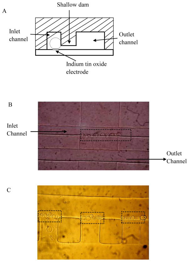
Hydraulic pressure pumping and vacuuming were usually chosen over electroosmotic pumping to transport cells along the channel, because high voltage may affect the cell state and vitality.25, 26 To simplify the experiment setup, the transportation of cells was regulated by adjusting the difference of solution height between the inlet reservoir and the outlet reservoir without employing any high pressure/vacuum system. The schematic diagram of microfluidic chip with cell trapping design is shown in Fig. 3A. It shows that cells traveled through the inlet channel, trapped along the entrance of the shallow channel and settled on top of the ITO electrodes at the same time, while solutions and small cell debris can flow freely inside all the channels. Initially, ~10 μl buffer containing ~104 cell/ml of bovine adrenal chromaffin cells was placed in the inlet reservoir; cells started to flow hydrodynamically. Many reports focused on manipulating cells to the small aperture fabricated near the microelectrodes by high pressure/vacuum.18, 27 In these reports, a balance must be achieved between using a pressure gradient sufficiently large to bring the cells to trapping spot yet be gentle enough to avoid cell damage or induce unintended effects on exocytosis, which is sensitive to membrane tension.28 Also, during cell loading and trapping, an increasing pressure was needed to bring more cells to the uncovered spots, which can build up the pressure gradient inside the channel and may damage cells. In avoid of these problems, cell trapping devices with more shallow channels and wider outlet channel were developed, which can help to alleviate the internal pressure when some shallow channels are blocked by cells. In our case, a 20 μm wide, 20 μm deep inlet channel and a 40 μm wide, 20 μm deep outlet channel were designed to be connected with a series of shallow channels described below.
Fig. 3.
(A) Schematic diagram of the cell trapping device, (B) Micrograph of chromaffin cell trapping at a 100 μm wide, 2.5 μm deep channel, (C) Micrograph of chromaffin cell trapping at a 50 μm wide, 2.5 μm deep channels.
As the mean diameter of chromaffin cells is about 16 μm, 24 ideally vertical channels with depth less than 16 μm could be used to trap cells. But the hydraulic pressure inside the channel can expand the PDMS elastomer, therefore, the trapping structure needs to be much smaller than the cell diameter. Actually, we fabricated various depth (2–15 μm) of shallow channels by adjusting the spin-coating speed. It was found that, when the depth of the shallow channel is ≥3μm, cells can not be trapped at the entrance of the shallow channel for enough time to perform cell stimulating, because the hydraulic pressure of the cell solution and stimulating solution force the cells to squeeze into the shallow channel and eventually exit to the waste reservoir. The thickness of the channel was optimized as 2.5 μm to perform cell docking efficiently. Fig. 3B shows ~10 chromaffin cells were trapped at a 100 μm width, 2.5 μm depth channel, and there are a total of 5 parallel channels in these devices. Fig. 3C shows ~5 chromaffin cells were trapped at each channel with 50 μm in width and 2.5 μm in depth. We quantified cell trapping on 10 shallow channels with a width of 50 μm, and it was calculated hat 36 of the 50 possible trapping sites (72%) are occupied by cells. When shrinking the shallow channel features to 10 μm wide, only one or two cells can be trapped at each channel.
Amperometric measurements and spike analysis
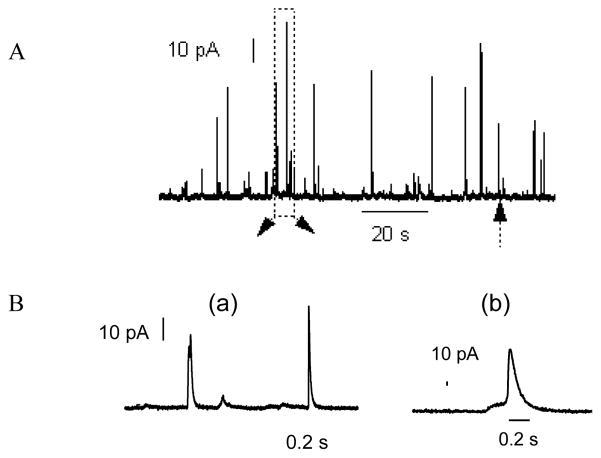
Arrays of microelectrodes can be used to electrochemically measure the released neurotransmitters from exocytosis, which offer the unique advantages of providing quantitative information about the amount of released molecules and precise kinetic characteristics with high sensitivity and sub-millisecond time resolution.29, 30 By placing microelectrodes at the entrance of the shallow channels, single cell exocytosis measurement can be achieved. Fig. 4 shows a small number of cells trapped along the entrance of shallow channel, there is one or two cells at maximum settled on each electrode. The cell trapping process can be completed in 30 seconds, and then cell solution in inlet reservoir was replaced with the stimulating solution. Exocytosis events were initiated immediately by flowing high K+ solution (100 mM). Amperometric spikes were recorded from 16 out of 20 cells, this indicates that the cells trapped on the device are viable. Fig. 5A displays a 120 s amperometric recording of exocytotic events detected at a single bovine adrenal chromaffin cell by ITO microelectrode. Each current transient reflects the release dynamics during exocytosis, most of the spikes started with a sharp increase in the current, as is shown the amperometric spikes on expanded time scale in Fig. 5B (a). While some of the events are, however, preceded by a foot signal, as is in Fig. 5B (b), which is similar to those reported recordings with conventional CFEs.31 It has been explained that these amperometric foot signals reflect a slow release of catecholamines through the early nanometer-sized fusion pore compared with the rapid release in Fig. 5B (a).32
Fig. 4.
Chromaffin cell trapping on top of the ITO electrodes. Each square crossed a cell or small cell clumps.
Fig. 5.
(A) Amperometric detection of quantal exocytosis of catecholamines from chromaffin cells using microfluidic cell trapping devices. (B) a, Expanded scale of the amperometric spikes within the dashed box in Fig. 5(A), b, Expanded view of the foot signal.
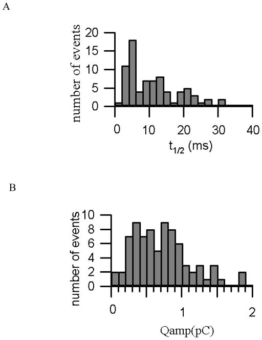
The device was cleaned and reloaded with cells between each experiment. As with recordings using conventional carbon fiber electrodes, the spike amplitudes and time courses vary between experiments. One source of variation is the non-uniform distance that catecholamines must diffuse between the release site on the cell and the electrode surface as well as heterogeneity in vesicle contents and fusion kinetics. In order to accurately monitor the time course and areas of spike of released catecholamines from single vesicles, we quantified the amperometric spikes by determining the amperometric charge (Qamp), which corresponds to the number of catecholamine molecules collected by ITO microelectrodes during an individual event; and spike duration (t1/2), the time interval that the spike exceeds the half-maximal value. We pooled the results from a total of 79 events from a set of single cell exocytosis experiment and analyzed individually to determine the time course and areas of spike. Histograms of the time course (t1/2) and areas of spikes (Qamp) were presented in Fig. 6A and Fig. 6B. The distribution of t1/2 values showed a half-width of a few milliseconds, with a mean value of 12.23 ms. And the average rise time is 2.7 ms, the mean Qamp value is 0.76 pC (or 3.96 amol/vesicle), which are within the range typically reported for bovine adrenal chromaffin cells using carbon-fiber electrodes.33, 34
Fig. 6.
(A) Histogram of the spike “half-widths” as a measure of spike duration, the half-width is defined as the time interval for each spike where the amperometric current exceeds 50% of the peak value of the spike, (B) Histograms of spike area as a measure of the catecholamine content of a single vesicle.
Conclusions
We have designed and manufactured an effective cell trapping device suitable for high-throughput amperometric measurement of quantal exocytosis from individual cells without the need of the advanced fabrication facility. Single or small ensembles of chromaffin cells can be positioned according to the dimension of the channel, single cell analysis can be achieved by placing an indium tin oxide microelectrodes in the designed trapping channel. It offered an efficient method to target cells to electrode in a relatively simple manner without the need for precise pressure control and fluid handling. The obtained data from the microfluidic device was in agreement with those published from measurements using conventional carbon fiber microelectrodes.
Supplementary Material
References
- 1.Grace AA. Neuroscience. 1991;41:1–24. doi: 10.1016/0306-4522(91)90196-u. [DOI] [PubMed] [Google Scholar]
- 2.Monck JR, Fermnndez JM. J Cell Biol. 1992;119:1395–1404. doi: 10.1083/jcb.119.6.1395. [DOI] [PMC free article] [PubMed] [Google Scholar]
- 3.Zimmerberg J, Cyrran M, Cohen FS, Brodwick M. Proc Natl Acad Sci. 1987;84:1585–1589. doi: 10.1073/pnas.84.6.1585. [DOI] [PMC free article] [PubMed] [Google Scholar]
- 4.Kennedy RT, Huang L, Atkinson MA, Dush P. Anal Chem. 1993;65:1882–1886. doi: 10.1021/ac00062a012. [DOI] [PubMed] [Google Scholar]
- 5.Wang W, Zhang SH, Li LM, Wang ZL, Cheng JK, Huang WH. Anal Bioanal Chem. 2009;394:17–32. doi: 10.1007/s00216-009-2703-2. [DOI] [PubMed] [Google Scholar]
- 6.Velve–Casquillas G, Le Berre M, Piel M, Tran PT. Nano Today. 2010;5:28–47. doi: 10.1016/j.nantod.2009.12.001. [DOI] [PMC free article] [PubMed] [Google Scholar]
- 7.Carabelli V, Gosso S, Marcantoni A, Xu Y, Colombo E, Gao Z, Vittone E, Kohn E, Pasquarelli A, Carbone E. Biosens Bioelectron. 2010;26:92–98. doi: 10.1016/j.bios.2010.05.017. [DOI] [PubMed] [Google Scholar]
- 8.Sun X, Gillis KD. Anal Chem. 2006;78:2521–2525. doi: 10.1021/ac052037d. [DOI] [PubMed] [Google Scholar]
- 9.Dittami GM, Rabbitt RD. Lab Chip. 2010;10:30–35. doi: 10.1039/b911763f. [DOI] [PMC free article] [PubMed] [Google Scholar]
- 10.Shi BX, Wang Y, Zhang K, Lam TL, Chan HLW. Biosens Bioelectron. 2011;26:2917–2921. doi: 10.1016/j.bios.2010.11.037. [DOI] [PubMed] [Google Scholar]
- 11.Liu X, Barizuddin S, Shin W, Mathai CJ, Gangopadhyay S, Gillis KD. Anal Chem. 2011;83:2445–2451. doi: 10.1021/ac1033616. [DOI] [PMC free article] [PubMed] [Google Scholar]
- 12.Meunier A, Jouannot O, Fulcrand R, Fanget I, Bretou M, Karatekin E, Arbault S, Guille M, Darchen F, Amatore C. Angew Chem Int Ed. 2011;50(22):5081–5084. doi: 10.1002/anie.201101148. [DOI] [PubMed] [Google Scholar]
- 13.Amatore C, Arbault S, Chen Y, Crozatier C, Lemaître F, Verchier Y. Angew Chem Int Ed. 2006;45(24):4000–4003. doi: 10.1002/anie.200600510. [DOI] [PubMed] [Google Scholar]
- 14.Shi B, Wang Y, Lam T, Huang W, Zhang K, Leung Y, Chan HLW. Biomicrofluidics. 2010;4:043009. doi: 10.1063/1.3491470. [DOI] [PMC free article] [PubMed] [Google Scholar]
- 15.Klemic KG, Klemic JF, Reed MA, Sigworth FJ. Biosens Bioelectron. 2002;17:597–604. doi: 10.1016/s0956-5663(02)00015-5. [DOI] [PubMed] [Google Scholar]
- 16.Fertig N, Blick RH, Behrends JC. Biophys J. 2002;82:3056–3062. doi: 10.1016/S0006-3495(02)75646-4. [DOI] [PMC free article] [PubMed] [Google Scholar]
- 17.Huang Y, Cai D, Chen P. Anal Chem. 2011;83:4393–4406. doi: 10.1021/ac200358b. [DOI] [PubMed] [Google Scholar]
- 18.Spegel C, Heiskanen A, Pedersen S, Emneus J, Ruzgas T, Taboryski R. Lab Chip. 2008;8:323–329. doi: 10.1039/b715107a. [DOI] [PubMed] [Google Scholar]
- 19.Unger MA, Chou HP, Thorsen T, Sherer A, Quake SR. Science. 2000;288:113–116. doi: 10.1126/science.288.5463.113. [DOI] [PubMed] [Google Scholar]
- 20.Dias AF, Dernick G, Valero V, Yong MG, James CD, Craighead HG, Lindau M. Nanotechnology. 2002;13:285–289. [Google Scholar]
- 21.Amatore C, Arbault S, Chen Y, Crozatier C, Tapsoba I. Lab Chip. 2007;7:233–238. doi: 10.1039/b611569a. [DOI] [PubMed] [Google Scholar]
- 22.Wheeler AR, Throndset WR, Whelan RJ, Leach AM, Zare RN, Liao YH, Farrell K, Manger ID, Daridon A. Anal Chem. 2003;75:3581–3586. doi: 10.1021/ac0340758. [DOI] [PubMed] [Google Scholar]
- 23.Yao J, Gillis KD. Analyst. 2012;137:2674–2681. doi: 10.1039/c2an35157a. [DOI] [PMC free article] [PubMed] [Google Scholar]
- 24.Plattner H, Artalejo AR, Neher E. J Cell Biol. 1997;139(7):1709–1717. doi: 10.1083/jcb.139.7.1709. [DOI] [PMC free article] [PubMed] [Google Scholar]
- 25.Bogojevic D, Chamberlain MD, Barbulovic-Nadab I, Wheeler AR. Lab Chip. 2012;12:627–634. doi: 10.1039/c2lc20893h. [DOI] [PubMed] [Google Scholar]
- 26.Yi C, Ji S, Yang M. Anal Chim Acta. 2006;560:1–23. [Google Scholar]
- 27.Gao Y, Bhattacharya S, Chen X, Barizuddin S, Gangopadhyay S, Gillis KD. Lab Chip. 2009;9:3442–3446. doi: 10.1039/b913216c. [DOI] [PubMed] [Google Scholar]
- 28.Cui HF, Ye JS, Chen Y, Chong SC, Liu X, Lim TM, Sheu FS. Sens Actua B: Chem. 2006;115:634–641. [Google Scholar]
- 29.Schroeder TJ, Borges R, Finnegan JM, Pihel K, Amatore C, Wightman RM. Biophys J. 1996;70:1061–1068. doi: 10.1016/S0006-3495(96)79652-2. [DOI] [PMC free article] [PubMed] [Google Scholar]
- 30.Kisler K, Kim B, Berberian K, Fang Q, Lindau M. Biophys J. 2007;92:83a. [Google Scholar]
- 31.Chow RH, Rüden LV, Neher E. Nature. 1992;356:60–63. doi: 10.1038/356060a0. [DOI] [PubMed] [Google Scholar]
- 32.Albillos A, Dernick G, Horstmann H, Almers W, Alvarez de Toledo G, Lindau M. Nature. 1997;389:509–512. doi: 10.1038/39081. [DOI] [PubMed] [Google Scholar]
- 33.Chow RH, Von Ruden L, Neher E. Nature. 1992;356:60–63. doi: 10.1038/356060a0. [DOI] [PubMed] [Google Scholar]
- 34.Wightman RM, Schroeder TJ, Finnegan JM, Ciolkowski EL, Pihel K. Biophys J. 1995;68:383–390. doi: 10.1016/S0006-3495(95)80199-2. [DOI] [PMC free article] [PubMed] [Google Scholar]
Associated Data
This section collects any data citations, data availability statements, or supplementary materials included in this article.


