Abstract
Three dimensional (3-D) printing technology has evolved dramatically in the last few years, offering the capability of printing objects with a variety of materials. Printing microfluidic devices using this technology offers various advantages such as ease and uniformity of fabrication, file sharing between laboratories, and increased device-to-device reproducibility. One unique aspects of this technology, when used with electrochemical detection, is the ability to produce a microfluidic device as one unit while also allowing the reuse of the device and electrode for multiple analyses. Here we present an alternate electrode configuration for microfluidic devices, a wall-jet electrode (WJE) approach, created by 3-D printing. Using microchip-based flow injection analysis, we compared the WJE design with the conventionally used thin-layer electrode (TLE) design. It was found that the optimized WJE system enhances analytical performance (as compared to the TLE design), with improvements in sensitivity and the limit of detection. Experiments were conducted using two working electrodes – 500 μm platinum and 1 mm glassy carbon. Using the 500 μm platinum electrode the calibration sensitivity was 16 times higher for the WJE device (as compared to the TLE design). In addition, use of the 1 mm glassy carbon electrode led to limit of detection of 500 nM for catechol, as compared to 6 μM for the TLE device. Finally, to demonstrate the versatility and applicability of the 3-D printed WJE approach, the device was used as an inexpensive electrochemical detector for HPLC. The number of theoretical plates was comparable to the use of commercially available UV and MS detectors, with the WJE device being inexpensive to utilize. These results show that 3D-printing can be a powerful tool to fabricate reusable and integrated microfluidic detectors in configurations that are not easily achieved with more traditional lithographic methods.
1. INTRODUCTION
Microchip-based systems provide an attractive analytical and separation platform due to the ability of using small sample volumes,1 performing fast/high-throughput analysis2, 3 and being able to integrate different detection systems.4–7 Electrochemical detection is becoming a popular means for detection in microfluidic devices because for many analytes it enables direct and label free detection with no derivatization steps.4 Many groups have worked in this area of research.8, 9 One advance in this area was described by Henry and Garcia, who developed a device that combines microchip electrophoresis with pulsed amperometric detection (PAD) for the separation of underivatized carbohydrates, amino acids and sulfur containing antibiotics.10 Another example comes from the Lunte group, who developed a method for separating and directly detecting peroxynitrite, which has a very short half-life, by utilizing a microchip electrophoresis device and amperometric detection.11 Our group has several published approaches that involve the use of integrating multiple processes with microchip-based systems, such as the immobilization and analysis of neurotransmitters released from various cell lines via electrochemical detection.4, 12, 13
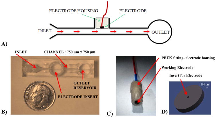
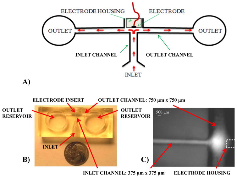
One issue that needs to be considered with these systems is the manner in which the working electrode is integrated with the microchannel network. So far, many reports of electrochemical detection in microfluidic devices have used thin-layer electrodes (TLE), which are planar electrodes aligned along a microfluidic channel, with the electrode surface parallel with flow. While a sample (usually a discrete plug) is flowing along the electrode surface, molecules in a thin liquid layer close to the electrode can diffuse to the electrode and be subsequently detected (Figure 1A).14–16 However, with TLE integrated microfluidic devices the issue of limited sensitivity still remains because only the molecules along the electrode surface are detected.17 The widespread use of TLE design in microchip devices is primarily due to the planar (two dimensional) nature of traditional fabrication techniques and the difficulty associated with 3-dimensonal microchip fabrication. A wall jet electrode (WJE) is an alternative electrode configuration that has been reported for tubing-based systems.18–20 A WJE design (Figure 2A) allows the sample to hit the electrode embedded at the end the sample inlet channel, perpendicular to the inlet flow stream, which has proven to enhance mass transport and thus increase sensitivity. Although there are a few reports showing the integration of WJE in microfluidic devices, they used glass microchannels (requiring clean room for fabrication) and the electrode has to be manually aligned with the separation channel since the electrode is separate from the microchip.21–23
Figure 1.
Thin-layer electrode (TLE) device and electrode fabrication. (A) Schematic of the side profile of the TLE depicting the flow profile; (B) Top view of the 3-D printed TLE device. The threaded port on the left is for the sample inlet and the center threaded port allows the integration of various working electrodes. The auxiliary and reference electrodes are put into the outlet reservoir; (C) An assembled 500 μm Platinum working electrode within a PEEK fitting.; (D) A CAD schematic of a printed disk used to center the electrode within the PEEK fitting during assembly.
Figure 2.
Wall-jet electrode (WJE) design. (A) Schematic of the WJE device. As depicted, the sample flow hits the electrode normal to the surface and then flows away radially. This flow regime allows to increase mass transfer of the analyte thus increasing the sensitivity; (B) Top view of the 3-D printed WJE device. The electrode insert is threaded to enable the integration of electrodes; (C) Micrograph of a fluorescein plug hitting the electrode in the WJE design and flowing away from the electrode (electrode location denoted with dotted line for clarity).
As compared to the lithographic-based fabrication of devices, three dimensional (3D) printing is an attractive approach for device design and creation. 3D-printing is a rapid prototype technology that can build a 3D configuration in a “layer-by-layer” process. This technology is being incorporated into many different areas to reduce costs and time associated with traditional manufacturing methods, for example ramping up production time lines in various manufacturing sectors;24 however it has also provided a new approach to teaching, for example building body parts to teach anatomy in medical schools.25 With this technology, one can print any shape and add threaded features within a design simply by sending a CAD drawing to a 3D-printer. There have been various groups who have incorporated this technology into the chemical sciences.26 There has also been recent interest in using 3D-printing for enabling analytical measurements. For example, the Foret group has 3D printed a fluorescence detector that can be used for on-capillary separation.27 In addition, the Breadmore group reported a cost effective and fast method of printing microfluidic to millifluidic devices using a transparent resin that can be used for optical detection.28 Spence and colleagues, who were the first to describe the use of 3D-printing to fabricate microfluidic systems, have shown that the resulting devices can be easily integrated with other commercial instruments, such as a microplate reader.3, 29, 30 Compared to glass or PDMS-based microfluidic devices; 3D-printing enables the fabrication of device in one step, without bonding several components together. These reported 3D-printed devices are also reusable and the CAD drawing can be easily shared between laboratories, increasing reproducibility between analysts and laboratories. In addition, the devices are inexpensive to create and can be used for a variety of chemistry teaching applications.31, 32
A collaboration project between the Spence and Martin groups has recently reported a 3D-printed TLE microfluidic device that can be used to detect biologically important molecules such as nitric oxide using amperometry. 33 In this paper, we present a step forward to 3D-printing reusable and versatile microfluidic device with WJE-based electrochemical detection. It is shown that 3D-printing also enables the fabrication of threaded ports that can connect tubing and electrodes via commercial fluidic fittings. In addition to reusability, the device permits convenient and rapid replacement of electrodes, which allows a researcher to change desired electrode without fabricating a new device. Characterization of the WJE device design involved the optimization of both the inlet and outlet channel dimensions, which affect analytical performance. This was followed by a study where the analytical performance (sensitivity and limit of detection) of the WJE device was compared to the TLE device. As a demonstration of the utility of the WJE device, it was utilized as an electrochemical detector for HPLC.
2. EXPERIMENTAL
2.1 Materials
The following chemicals and materials were used as received: catechol, dopamine, epinephrine, TES sodium salt, sodium phosphate dibasic (Sigma Aldrich, St. Louis, MO, USA) and sodium phosphate monobasic (Mallinckroft, St. Louis, MO, USA); Armstrong C-7 resin and Activator A, (Ellsworth Adhesives, Germantown, WI, USA); Loctite 5 minute clear epoxy (Home Depot); 1 mm glassy carbon and 500 μm platinum wire (Alfa Aesar, Ward Hill, MA, USA); copper electrical wire, soldering wire and heat shrink tubes (Radioshack); colloidal silver (Ted Pella, Redding, CA, USA); Size 10 and 12 embroidery needle (Walmart); Fingertight fitting F-120X, Capillary tubing connectors F-230 and Super Flangeless Fitting P-131 (IDEX Health & Science, Oak Habor, WA); BAS electrode polishing kit (Bioanalytical Systems Inc, West Lafayette, IN, USA); 50 μm and 75 μm ID flexible fused silica capillary tubing (Polymicro Technologies, Lisle, IL, USA); isopropanol (Fisher Scientific, Springfield, NJ, USA); formic acid LC-MS grade (Thermo Scientific, New York, USA).
2.2 Electrode Fabrication
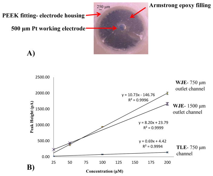
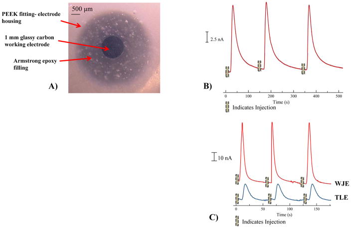
We have previously reported the use of epoxy embedded electrodes, which enables the incorporation of a variety of electrode materials.34 For the fabrication of the electrodes in the IDEX Flangeless Fitting, the desired wire (1 mm diameter glassy carbon or 500 μm diameter platinum) is affixed (soldered and connected with colloidal silver) to a copper extending wire to provide the electrical connection. Heat shrink tubing is used to insulate the connection before affixing it into the Flangeless Fitting. To ensure proper centering of the electrode within the Flangeless Fitting, disks of various thicknesses (diameter - 3.2 mm, hole size - 0.25 mm and varying thickness - 0.5 to 2.0 mm) were 3D printed (Figure 1D) and placed into the Flangeless Fitting opening to provide more rigidity and stability during the fabrication process. In this work, the electrode is inserted into the Flangeless Fitting and 3D printed inserted disk until the electrode is protruding from the top. In order to accommodate larger electrodes (0.5 mm and 1 mm), a size 10 or 12 embroidery needle is used to increase the hole size. Epoxy (5- minute clear) is applied to the base to hold the electrical wire within the Flangeless Fitting base. Following the assembly, a thoroughly mixed combination of 0.575 g Armstrong C-7 adhesive (resin) and 0.048 ml Armstrong Activator A is applied drop wise onto the electrode. The mixture is then cured over night at room temperature followed by wet polishing to allow the electrode to become flush with the Flangeless Fitting. Figure 1C shows an assembled working electrode in the IDEX fitting. Figure 3A and 4A (500 μM platinum and 1 mm glassy carbon electrodes respectively) show micrographs of the assembled working electrodes after wet polishing to ensure a leveled surface.
Figure 3.
Comparison between WJE and TLE devices using a 500 μm Platinum (Pt) working electrode. (A) Micrograph of a centered 500 μm Platinum working electrode within a PEEK fitting; (B) Same day TLE vs. WJE comparison by a catechol calibration curve (25 μM – 200 μM) in TES buffer (pH 7.4). In addition, a WJE comparison of two different outlet channel sizes (750 μm × 750 μm and 1500 μm × 1500 μm) is shown (n = 3 and error bars = standard deviation).
Figure 4.
Characterization of the WJE design using 1 mm glassy carbon working electrode. ( A) Micrograph of a centered 1 mm Glassy Carbon working electrode within a PEEK fitting; (B) Three consecutive peaks of 200 μM Catechol in TES buffer (pH 7.4), depicting the reproducibility of 200 nL sample plug size with an average peak height 15.0 ± 0.3 nA (n = 3 and error = standard deviation); (C) Signal intensity comparison between WJE and TLE designs using 3 consecutive injections (plug size = 40 nL) of a 200 μM catechol sample in TES buffer (pH = 7.4).
2.3 Fabrication of 3-D Printed Microfluidic Devices
The devices used in these studies were designed using Autodesk Inventor Professional 2014 (San Rafael, CA, USA). The standard tessellation language file (.STL file) was used by the printer (Objet Eden 260V, Stratasys, Ltd., Edina, MN, USA) to create the devices. The printing material used in this work was Full Cure 720 and Full Cure 705 support material (Stratasys, Ltd., Edina, MN, USA). The composition of the Full Cure 720 material is propriety, but approximately containing 10–30 % isobornyl acrylate, 10–30 % acrylic monomer, 15–30% acrylate oligomer, 0.1–1 % photo initiator. After removing majority of the support material from the device by high pressure water or by hand, a quick rinse with isopropanol allows for some of the leftover support material to be removed. Figure 1B shows the TLE design device and figure 2B shows the WJE design post printing and cleaning.
2.4 Measurement of catechol on the WJE and TLE devices
Catechol standards (varying concentrations 0.5 μM–200 μM) were used for the comparison between the two devices and the characterization of the WJE device. These solutions were prepared in TES buffer (pH 7.4) from a 10 mM catechol stock solution. A TES buffer flow stream was continuously pumped at 3.0 μL/min to the device via a 500 μL syringe (SGE Analytical Science) and a syringe pump (Harvard 11 plus, Harvard Apparatus, Holliston, MA, USA). The syringe was connected to a 75 μm ID capillary tubing using a finger tight PEEK fitting and a luer adapter (Upchurch Scientific, Oak Harbor, WA, USA). The same connectors and a 75 μm ID capillary were used to transition from a 4-port injection valve (Vici Rotor, Valco Instruments, Houston, TX, USA) to the microchip. A four port injection valve enabled reproducible 200 nL injections to the microchip flow channel. Amperometric detection of catechol samples was performed with a 3 electrode system using a CH Instruments potentiostat (Austin, TX, USA) at 0.9 V. The working electrode can either be the 1 mm glassy carbon or the 500 μm platinum; platinum wire was used as the auxiliary and Ag/AgCl (3.0 M KCl filling solution) was the reference. The auxiliary and reference electrodes were placed in the outlet reservoir (for both devices) during the studies. This same method is used for making measurements on the TLE device.
2.5 Using the WJE device as a liquid chromatography detector
An isocratic solvent system was used, with a 0.1% formic acid solution being mixed with methanol in a 97.5: 2.5 percent ratio as the mobile phase. The column used was a Hypersil BDS C-18 HPLC column (5 μm particle size, 5 cm length, 4.6 mm i.d., Thermo Scientific, New York, USA). The LC-MS instrument used was LC-UV-MS-2010 EV (Shimadzu Scientific Instruments, INC, Maryland, USA) with a 5 μL sample loop and a flow rate of 0.2 mL/min. For UV detection, a deuterium lamp was used and a wavelength of 205 nm was monitored. MS detection was done in positive mode looking at a mass range of 100 – 350 m/z (event time-0.24 seconds and scan speed- 1000 amu/sec). To use the WJE device, the same LC system was used with the same tubing except instead of going to the UV detector it was directed to the WJE device. The elution order for these 2 analytes was determined by looking at the individual retention times for each analyte, in addition to confirmation by the MS fragment data. For the LC-MS run, peak identification was confirmed by fragments of each analyte, characteristic fragments for epinephrine was observed at 184 and 166 m/z while dopamine fragments were 154 and 137 m/z, as previously noted in literature.35 Smoothing of MS peaks was conducted via the Peak Fit program (Version 4, SPSS Inc., Hong Kong, China), using a Savitzky-Golay filter.
3 RESULTS AND DISCUSSION
3.1 Optimization of the 3D-printed WJE device
In this work, a WJE microfluidic device was 3D-printed and characterized (Figure 2B). The channel dimensions applied within the WJE device design are largely based on the resolution of the printer and the ease in which the support material is removed. The Objet Eden 260V used to fabricate the WJE device has a resolution of 1600 dots per inch (dpi) along the z axis and 600 dpi along the x and y- axis.36 This printer uses a wax-like support material to fill up the void spaces in the device design. This support material can be removed using high pressure water or by other tools such as tip cleaners. Though the printer can theoretically achieve smaller sizes, due to the difficulty of removing the support material from a small channel, the channel size of 375 μm × 375 μm was chosen for the inlet of the WJE device.
In tubing-based studies, it has been shown that to get a true WJE behavior, the outlet height (in our case, the outlet channel height, see Figure 2A) should be at least the same size or larger than the inlet nozzle width (in our case the inlet channel width, see Figure 2A).37, 38 Thus, in order to determine the optimized outlet channel size, devices with different outlet channel sizes (with the inlet channel size being held constant at 375 μm × 375 μm) were fabricated and compared by measuring plugs of catechol standards injected into the devices (microchip-based flow injection analysis). The outlet channel sizes explored were 375 μm × 375 μm, 750 μm × 750 μm, and 1500 μm × 1500 μm. Preliminary studies showed that the 375 μm × 375 μm outlet channel had flow problems such as inconsistent flow and air bubbles being trapped at the inlet-outlet channel junction. Same day measurements of catechol standards (25 – 200 μM) were conducted on the other two devices (with different outlet channel sizes) and calibration curves were acquired (peak current vs. concentration). Though both devices gave a linear correlation with concentration, the 750 μm × 750 μm outlet channel showed great analytical improvement. Figure 3B shows that the detection sensitivity using the 750 μm × 750 μm outlet channel is significantly higher (1.3 times) than the 1500 μm × 1500 μm outlet channel. Using a 500 platinum (Pt) wire detection electrode, the 750 μm × 750 μm outlet channel device had a limit of detection (LOD) for catechol of 4 μM, while the 1500 μm × 1500 μm device had a catechol LOD of 7 μM (a significant difference at the 95% confidence level). This can be rationalized by the 1500 μm × 1500 μm outlet channel having a larger area between the end of the inlet channel and the electrode, which leads to more analyte not being able to reach the electrode surface. Based on these comparisons, the outlet channel of 750 μm × 750 μm was selected as the optimized size (Figure 2B, C and D). This outlet channel size enables effective hitting of an analyte onto the electrode surface, with sufficient clearing the electrode once detection is finished. In addition to the outlet channel size optimization, large outlet reservoirs (14 mm diameter) at the ends of the outlet channels were implemented to hold the other electrodes (auxiliary and reference) and enable longer running of the device without emptying the reservoirs.
3.2 Comparison of 3D-printed WJE and TLE devices
WJE devices are expected to be more sensitive than TLE because of the higher mass transport to the detection electrode.19, 20 In this work, the optimized 3D-printed WJE device was compared with a 3D-printed TLE device. To ensure an accurate comparison, the TLE channel size is the same as the WJE outlet channel size where the electrode is housed (750 μm × 750 μm). The results of three consecutive injections of 200 μM catechol solution showed that the electrode response (for the 500 μm platinum working electrode) was reproducible, with an average peak current being 1.99 ± 0.04 nA for the WJE design and 0.14 ± 0.02 nA for the TLE. As can be seen, the WJE design exhibited a significantly higher peak height as well. Next, same day measurements of catechol standards were conducted on both WJE and TLE devices and calibration curves of current against catechol concentration were overlaid. As shown in Figure 3B, the sensitivity of WJE device is approximately 16 times higher than the TLE design (WJE: 10.7 ± 0.1 pA/μM vs. TLE: 0.68 ± 0.06 pA/μM, average of 3 different calibration curves for each). In addition, the LOD from the WJE design is significantly better than the TLE design (4 μM vs. 8 μM for WJE and TLE, respectively (a significant difference at the 95% confidence level). The higher sensitivity and lower LOD for the WJE device can rationalized by more efficient mass transport to the electrode surface.
An advantage of these 3D-printed devices is their versatility, as electrodes can easily be exchanged when desired.33 The results shown above were acquired using a 500 μm Pt electrode integrated to the device by a PEEK nut (serving as the electrode housing). The 3D-printed threaded port and the fabrication of an electrode in this PEEK nut make the integration of an electrode into the device a reversible process. For example, if another electrode of different size is needed for a certain measurement, a new PEEK nut that contains the desired electrode can be screwed into the 3D-printed microfluidic part. For analyzing catechol and catecholamine neurotransmitters glassy carbon working electrodes have been commonly used. Therefore, in this work, a 1 mm glassy carbon (GC) electrode was also fabricated (Figure 4A) and subsequently integrated onto the same 3D-printed microfluidic part in place of the Pt electrode. The LOD using the GC electrode is lower for the WJE device (500 nM vs. 6 μM for WJE and TLE respectively, a significant difference at the 95% confidence level). Figure 4B shows typical data of the WJE device with a glassy carbon electrode to detect a 200 μM catechol solution (using off-chip 4-port injector and a 200 nL injection volume). To further investigate the effect of the WJE on the electrode response, a smaller injection plug (40 nL) was obtained by pressure-based injection directly onto the capillary.39 As can be seen in Figure 4C (injection of a 200 μM catechol solution), the WJE electrode resulted more intense peaks (52 ± 6 nA), as compared to the use of the TLE approach (16 ± 2 nA, a significant difference at the 95% confidence level).
3.3 Using the 3D-printed WJE device as an inexpensive LC detector
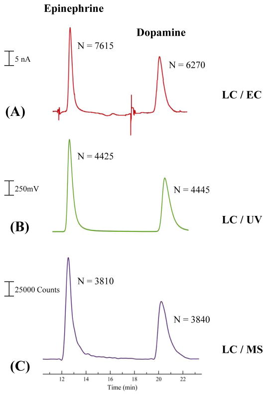
Due to the versatility of the 3D-printed WJE device, as well as the analytical enhancement relative to TLE approaches, the device was investigated as an inexpensive electrochemical (EC) detector for LC. Dopamine and epinephrine were separated by reverse phase LC (using an isocratic mobile phase of 0.1% formic acid: methanol 97.5:2.5 %) and detected with the WJE device. Two other commercially available detectors, UV and mass spectrometry (MS) were used as reference methods. For UV detection, a wavelength of 205 nm was used for both analytes. For both UV and MS detection, the retention times for epinephrine and dopamine were 12.7 minutes and 21.2 minutes, respectively. Following this experiment, the tubing from the column was disconnected from the UV detector and directed into the WJE device for EC detection. The retention times for the 2 analytes were the same as the UV and MS detection. By comparing the three chromatograms (as shown in Figure 5), it can be seen that the WJE has a similar separation performance (in terms of the number of theoretical plates) to LC-UV and LC-MS, meaning this optimized WJE design is an attractive alternative to commercially available detection systems.
Figure 5.
Chromatographs of epinephrine and dopamine separation. (A) Electrochemical detection using the WJE device; (B) UV detection; (C) MS detection
The cost associated with buying a LC electrochemical flow-cell can range from $800 – $1250 (excluding the column) depending on the type of working electrode used (based upon data from Bioanalytical Systems Inc).40 On the other hand, the cost associated of printing the WJE device used here is approximately $25 (this cost does not include the cost of the printer and we were granted free access). The electrodes used in these studies are interchangeable and can be used for long periods of time (month-to-years). Each 500 μm Pt electrode costs $34 to make, while the 1 mm glassy carbon electrodes costs $56 (both include the fitting and material cost), resulting in the total device cost ranging from $59 to $80 (most of the cost is purchasing of the Pt or carbon electrode materials). In addition, subsequent devices can be printed on demand and shared between other labs easily.
4 CONCLUSION
3D-printing was used to fabricate a WJE configuration for microchip-based electrochemical detection, with the resulting design having improved mass transport on the electrode surface and sensitivity when compared to TLE designs. Comparison studies between this WJE device and a TLE configuration (using catechol as a model analyte) showed significant improvements in sensitivity and the LOD for the WJE approach. Moreover, the electrode integration onto the 3D-printed microfluidic part is reversible and replaceable. This is an important feature of the device, allowing a researcher to change desired electrodes without fabricating a new device (something that is not easily done with fabricated microfluidic devices). Lastly, the WJE device was tested as an electrochemical detector for HPLC, the results of which showed that this 3D-printed detector is comparable in performance to commercially available UV and MS detectors. These results show that 3D-printing can be a powerful tool to fabricate reusable and integrated microfluidic detectors in configurations that cannot be achieved with more traditional lithographic methods.
Acknowledgments
Support from the National Institute of General Medical Sciences (Award Number R15GM084470-04) is acknowledged.
References
- 1.Li MW, Bowen AL, Batz NG, Martin RS. In: Lab on a Chip Technology, Part II: Fluid Control and Manipulation. Herold KE, Rasooly A, editors. Caister Academic Press; UK: 2009. pp. 385–403. [Google Scholar]
- 2.Jacobson SC, Culbertson CT, Daler JE, Ramsey JM. Anal Chem. 1998;70:3476–3480. [Google Scholar]
- 3.Chen C, Wang Y, Lockwood SY, Spence DM. Analyst. 2014;139:3219–3226. doi: 10.1039/c3an02357e. [DOI] [PubMed] [Google Scholar]
- 4.Bowen AL, Martin RS. Electrophoresis. 2010;31:2534–2540. doi: 10.1002/elps.201000029. [DOI] [PMC free article] [PubMed] [Google Scholar]
- 5.Genes LI, Tolan NV, Hulvey MK, Martin RS, Spence DM. Lab Chip. 2007;7:1256–1259. doi: 10.1039/b712619k. [DOI] [PubMed] [Google Scholar]
- 6.Noblitt SD, Lewis GS, Liu Y, Hering SV, Collett JL, Henry CS. Anal Chem. 2009;81:10029–10037. doi: 10.1021/ac901903m. [DOI] [PubMed] [Google Scholar]
- 7.Batz NG, Mellors JS, Alarie JP, Ramsey JM. Anal Chem. 2014;86:3493–3500. doi: 10.1021/ac404106u. [DOI] [PubMed] [Google Scholar]
- 8.Randviir EP, Banks CE. Electrophoresis. 2015;36:1845–1853. doi: 10.1002/elps.201500153. [DOI] [PubMed] [Google Scholar]
- 9.Saylor RA, Lunte SM. J Chromatogr A. 2015;1382:48–64. doi: 10.1016/j.chroma.2014.12.086. [DOI] [PMC free article] [PubMed] [Google Scholar]
- 10.García CD, Henry CS. Anal Chem. 2003;75:4778–4783. doi: 10.1021/ac034440v. [DOI] [PubMed] [Google Scholar]
- 11.Hulvey MK, Frankenfeld CN, Lunte SM. Anal Chem. 2010;82:1608–1611. doi: 10.1021/ac902821v. [DOI] [PMC free article] [PubMed] [Google Scholar]
- 12.Selimovic A, Martin RS. Electrophoresis. 2013;34:2092–2100. doi: 10.1002/elps.201300163. [DOI] [PMC free article] [PubMed] [Google Scholar]
- 13.Johnson AS, Mehl BT, Martin RS. Anal Methods. 2015;7:884–893. doi: 10.1039/C4AY02569E. [DOI] [PMC free article] [PubMed] [Google Scholar]
- 14.Yildiz A, Kissinger PT, Reilley CN. Anal Chem. 1968;40:1018–1024. [Google Scholar]
- 15.Blaedel WJ, Wang J. Anal Chem. 1981;53:78–80. [Google Scholar]
- 16.Hyk W, Stojek Z. Electrochem Commun. 2013;34:192–195. [Google Scholar]
- 17.Chen JG, Woltman SJ, Weber SG. In: Advances in Chromatography. Brown PR, Grushka E, editors. Vol. 36. Marcel Dekker; New York: 1995. pp. 273–313. [PubMed] [Google Scholar]
- 18.Laevers P, Hubin A, Terryn H, Vereecken J. J Appl Electrochem. 1995;25:1017–1022. [Google Scholar]
- 19.Ball JC, Compton RG, Brett CMA. J Phys Chem B. 1998;102:162–166. [Google Scholar]
- 20.Compton RG, Fisher AC, Latham MH, Brett CMA, Brett AMCFO. J Phys Chem. 1992;96:8363–8367. [Google Scholar]
- 21.Pan J, Chen Z, Yao M, Li X, Li Y, Sun D, Yu Y. Luminescence. 2014;29:427–432. doi: 10.1002/bio.2565. [DOI] [PubMed] [Google Scholar]
- 22.Wang J, Polsky R, Tian B, Chatrathi MP. Anal Chem. 2000;72:5285–5289. doi: 10.1021/ac000484h. [DOI] [PubMed] [Google Scholar]
- 23.Wang J, Tian B, Sahlin E. Anal Chem. 1999;71:5436–5440. doi: 10.1021/ac990807d. [DOI] [PubMed] [Google Scholar]
- 24.D’Aveni R. Harvard Bus Rev. 2015 May;:40–48. [Google Scholar]
- 25.Gross BC, Erkal JL, Lockwood SY, Chen C, Spence DM. Anal Chem. 2014;86:3240–3253. doi: 10.1021/ac403397r. [DOI] [PubMed] [Google Scholar]
- 26.Kitson PJ, Rosnes MH, Sans V, Dragone V, Cronin L. Lab Chip. 2012;12:3267–3271. doi: 10.1039/c2lc40761b. [DOI] [PubMed] [Google Scholar]
- 27.Prikryl J, Foret F. Anal Chem. 2014;86:11951–11956. doi: 10.1021/ac503678n. [DOI] [PubMed] [Google Scholar]
- 28.Shallan AI, Smejkal P, Corban M, Guijt RM, Breadmore MC. Anal Chem. 2014;86:3124–3130. doi: 10.1021/ac4041857. [DOI] [PubMed] [Google Scholar]
- 29.Liu Y, Chen C, Summers S, Medawala W, Spence DM. Integr Biol. 2015;7:534–543. doi: 10.1039/c4ib00243a. [DOI] [PubMed] [Google Scholar]
- 30.Anderson KB, Lockwood SY, Martin RS, Spence DM. Anal Chem. 2013;85:5622–5626. doi: 10.1021/ac4009594. [DOI] [PubMed] [Google Scholar]
- 31.Rossi S, Benaglia M, Brenna D, Porta R, Orlandi M. J Chem Educ. 2015;92:1398–1401. [Google Scholar]
- 32.Kaliakin DS, Zaari RR, Varganov SA. J Chem Educ. 2015 doi: 10.1021/acs.jchemed.5b00409. [DOI] [PubMed] [Google Scholar]
- 33.Erkal JL, Selimovic A, Gross BC, Lockwood SY, Walton EL, McNamara S, Martin RS, Spence DM. Lab Chip. 2014;14:2023–2032. doi: 10.1039/c4lc00171k. [DOI] [PMC free article] [PubMed] [Google Scholar]
- 34.Selimovic A, Johnson AS, Kiss IZ, Martin RS. Electrophoresis. 2011;32:822–831. doi: 10.1002/elps.201000665. [DOI] [PMC free article] [PubMed] [Google Scholar]
- 35.Kushnir MM, Urry FM, Frank EL, Roberts WL, Shushan B. Clin Chem. 2002;48:323–331. [PubMed] [Google Scholar]
- 36.Stratsys 3D Printers. [accessed November 11, 2015];Objet Eden 260 V. http://www.stratasys.com/3d-printers/design-series/objet-eden260vs.
- 37.Chin DT, Tsang CH. J Electrochem Soc. 1978;125:1461–1470. [Google Scholar]
- 38.Elbicki JM, Morgan DM, Weber SG. Anal Chem. 1984;56:978–985. doi: 10.1021/ac00270a026. [DOI] [PubMed] [Google Scholar]
- 39.Becirovic V, Doonan SR, Martin RS. Anal Methods. 2013;5:4220–4229. doi: 10.1039/C3AY40809D. [DOI] [PMC free article] [PubMed] [Google Scholar]
- 40.BASi Flowcells. [accessed September 16, 2015];HPLC Electrochemical Detection. https://www.basinc.com/products/ec/flowcells.php.


