Abstract
The intermittent nature of the sunlight and its increasing contribution to electricity generation is fostering the energy storage research. Direct solar charging of an auspicious type of redox flow battery could make solar energy directly and efficiently dispatchable. The first solar aqueous alkaline redox flow battery using low cost and environmentally safe materials is demonstrated. The electrolytes consist of the redox couples ferrocyanide and anthraquinone‐2,7‐disulphonate in sodium hydroxide solution, yielding a standard cell potential of 0.74 V. Photovoltage enhancement strategies are demonstrated for the ferrocyanide‐hematite junction by employing an annealing treatment and growing a layer of a conductive polyaniline polymer on the electrode surface, which decreases electron–hole recombination.
Keywords: anthraquinone, electrochemistry, energy conversion, photoelectrodes, redox flow batteries
Wind and solar energy production is intermittent in nature, and the inherent mismatch between production and consumption in the electrical power grid ultimately limits extensive expansion of these power sources. A fully wind‐ and solar‐based future energy production will therefore depend on the development of electricity storage technologies that have significantly lower costs than the present ones.1 Herein, a potential future solar energy conversion technology with combined storage is investigated using low‐cost and environmentally benign materials. The main principles are illustrated in Figure 1.
Figure 1.
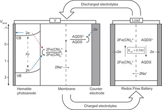
Energy diagram of the PEC/RF cell for solar charging of electrolytes connected to a RF cell for discharge. Desired electron‐hole pathways under light exposure are shown with full blue arrows. Undesirable back‐electron transfer is shown with red dotted arrow.
A photoelectrochemical/redox flow (PEC/RF) cell is built from a hematite photoanode immersed in an aqueous solution of ferrocyanide and NaOH and a graphite felt counter electrode immersed in an aqueous anthraquinone‐2,7‐disulphonate (AQDS) and NaOH solution separated by a cation conductive Nafion‐117 membrane. Upon illumination of the photoanode, electron–hole pair generation takes place in the hematite and holes move to the hematite surface oxidizing ferrocyanide through reaction (1):2
| (1) |
where ϕ 0′ is the formal electrochemical potential for the reaction. Meanwhile AQDS is reduced on the other side through reaction (2):
| (2) |
In the photo‐induced redox reactions, the photon energy is converted and stored directly as electrochemical energy. The process produces ferricyanide (Fe(CN)6 3−) and AQDS2− that correspond to charged species in the redox flow battery (RFB) and, when needed, can be converted into electricity in an RF cell as outlined in Figure 1.
The energy levels of the conduction and valence band of hematite under alkaline condition are found to be around −0.5 VNHE and +1.7 VNHE, respectively.3 With the potentials given in Equation (1) and (2), it is seen that the energy levels of the redox couples are in between those of the band gap of hematite, which is the primary requirement for unbiased photoelectrochemical charging under sunlight illumination. Herein it is shown that the hematite–ferrocyanide junction provides enough photovoltage to oxidize/reduce the ferrocyanide/AQDS redox pairs and thereby charge the redox flow battery unbiased.
However, the battery can only be charged unbiased up to about 10 % state‐of‐charge (SOC), where a fully charged and discharged battery corresponds to SOCs of 100 % and 0 %, respectively (ratio of the observed capacity to the nominal capacity). This means that experimental photovoltages are lower than expected from the band position considerations. The limiting factor of the photoelectrochemical charging process has been shown to be so‐called back electron recombination, where photogenerated electrons reduce ferricyanide (see Figure 1) instead of AQDS.2 Therefore preliminary tests with polyaniline surface modification of the hematite photoelectrode is shown to improve the photovoltage and the effect is attributed to intrinsic polyaniline electron photoexcitation and thus reduced back electron recombination.
Direct solar charging of redox species can be viewed as being analogous to PEC water splitting coupled with hydrogen fuel cells.3, 4 Despite the potential of PEC water splitting as a future storable energy source, key challenges remain. Especially with respect to obtaining higher solar conversion efficiency, the sluggish kinetics of water oxidation present a major challenge. On the other hand, solar electrochemical energy storage systems with combined conversion and storage cells were initially explored in the 1980s.5 Investigation focused on semiconductor‐electrolyte junctions in combined multi‐electrode conversion‐ and storage cells using both liquid and semisolid redox systems. Some of the challenges encountered then were lack of efficient, stable and cost‐efficient photoelectrodes and issues with membrane selectivity.5 Recently, the advantages of photo‐assisted charging of a lithium and iodide based battery has been demonstrated using a dye‐sensitized TiO2 photoelectrode, and direct photoelectrochemical response has been shown with TiO2 and an all vanadium aqueous and acidic RFB.6 Given the broad band gap of TiO2 (3.2 eV) and the instability of most well‐studied metal oxide semiconductors in acidic electrolytes, the applications of photoelectrodes with existing aqueous RFB technologies are limited. On the other hand, photocharging of redox couples in organic‐solvent RFBs using TiO2 have been demonstrated.7 However, as opposed to aqueous based ones, organic‐solvent RFBs struggle with issues such as low electrolyte conductivity and safety concerns.8 To date, no organic‐solvent RFBs have been commercialized. Recently the performance of an aqueous, alkaline RFB using only stable, non‐toxic, and low cost materials was reported with high efficiency, power density, and stability, which highlights the relevance of shifting to organic redox active molecules and high pH aqueous environments in RFB research.9 The solutions were composed of ferrocyanide and 2,6‐dihydroxyanthraquinone in NaOH solution, which is similar to the redox species used in the current work, where AQDS is used as the catholyte, owing to its suitable formal redox potential ϕ 0′=−0.25 VNHE at pH >10.10
The selected photoelectrode is hematite (α‐Fe2O3), which has been extensively studied as a photoanode and is perceived as a promising material, which is due in particular to its low band gap (E g=1.9–2.2 eV, CB≈−0.5 VNHE, and VB≈1.7 VNHE at pH 14), high stability in alkaline media, and low cost.2, 3, 11 The anode consists of the iron complex ferro/ferricyanide (Fe(CN)6 4−/Fe(CN)6 3−), which is a single‐electron redox couple electrochemically reversible under alkaline conditions and with a formal redox potential of ϕ 0′=0.49 VNHE at pH 13.2 Hematite photoanodes were prepared by spray pyrolysis on conductive glass in batches of 8 samples with subsequent surface treatment. Data are reported for two batches, A and B, for three types: 1) bare, 2) annealed, and 3) annealed with a thin layer of electrodeposited polyaniline on top, denoted hereafter as “coated” (Supporting Information, Section S1.
Cyclic voltammograms (CV) and battery charge–discharge behavior of ferrocyanide and AQDS in 1 m NaOH are shown in Figure 2 (see the Supporting Information, Section S2, for details). As seen from the CVs in Figure 2 a, the redox couples are electrochemically reversible and the redox potentials are as expected from previous reports.2, 10 The battery charge–discharge cycles were tested in a 25 cm2 single redox flow cell (RF) and the potential as function of time for ten cycles are shown in Figure 2 b. Charging and discharging capacities as a function of cycle number are shown in Figure 2 c and a high coulombic efficiency of around 98 % is observed. The overall RF cell performance is good and in line with the recently reported alkaline anthraquinone/ferrocyanide battery.9
Figure 2.
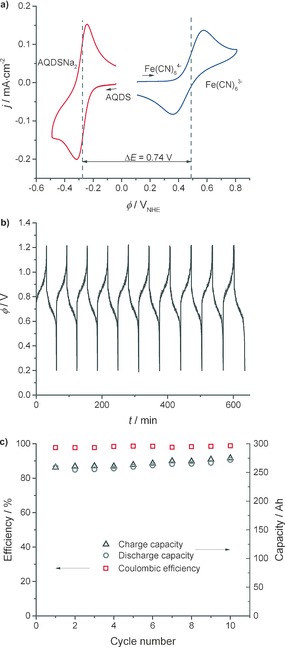
a) CVs of AQDS (red line) and Fe(CN)6 4− (blue line) 1 mm in 1 m NaOH at scan rate 100 mV s−1 on a GC electrode. b) 10 charge–discharge curves in a 25 cm2 RF cell with a constant current density of 20 mA cm−2 and electrolyte concentration 0.1 m AQDS and 0.2 m ferrocyanide in 1 m NaOH. c) Capacity data for the 10 cycles in (b). The energy efficiency is around 75 %.
Figure 3 a shows the photocurrent density (j) as function of the applied potential (ϕ) for three representative surface treated hematite samples. The data were recorded under 1 sun illumination with a three‐electrode setup in ferri/ferrocyanide solution only (Supporting Information, Section S3). When a pronounced increase in dark current was observed, the scan was terminated so as not to anodically corrode the electrode. The photo‐induced oxidative (positive) current has an onset around −0.15 to −0.05 VNHE depending on the sample, and dark oxidative current onset after 0.4 VNHE for the bare and annealed sample and after 0.65 VNHE for the coated. Onset potentials will in the following be referred to as ϕ on,photo and ϕ on,dark, respectively.
Figure 3.
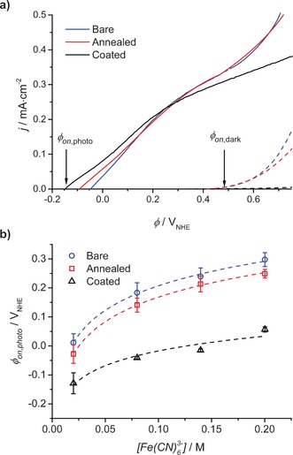
a) Current density (j) versus potential (ϕ) curves under 1 sun illumination (full lines) and in the dark (dashed lines) in the three‐electrode PEC cell for hematite samples from batch A (two bare, three annealed, and three coated) in 0.2 m K4Fe(CN)6, 1 m NaOH. b) Average ϕ on,photo and standard deviation for all samples from batch A from j−ϕ measurements with varying Fe(CN)6 3− concentration and a constant concentration of 0.2 m K4Fe(CN)6 and semi‐logarithmic regressions with slopes 122 mV (bare, R2=0.997), 122 mV (annealed, R2=0.999), and 73 mV (coated, R2=0.936).
Figure 3 b shows the average ϕ on,photo for different hematite samples as a function of ferricyanide concentration. It is seen that both surface treatments shifts ϕ on,photo towards a more negative potential, in particular for the coated samples. ϕ on,dark generally shifts to more positive potentials for coated samples (Figure 3 a). This indicates both an overall increased photovoltage and a higher available voltage for oxidation of ferrocyanide.12 From Figure 3 b it is also seen that ϕ on,photo shifts positively with increasing ferricyanide concentration; more precisely 122 mV per decade change in concentration for bare and annealed samples and only 73 mV for coated samples.
The photoresponse of bare and coated hematite samples were recorded in a PEC cell (S3.1) in a two‐electrode configuration using ferrocyanide on the anode and AQDS on the cathode side. The j−ϕ response of a representative bare hematite photoanode in the PEC cell at different SOCs is shown in Figure 4 a. Here, the oxidative photocurrent has an onset of about −0.3 V and is still observed with 0.07 mA cm−2 at 0 V and corresponds to unbiased solar PEC/RF cell charging. As the SOC increases to above 10 %, ϕ on,photo is observed at a slightly positive potential and unbiased photocharging no longer take place. Just before dark current onset the photocurrent is 0.10 mA cm−2. In Figure 4 b the j−ϕ responses of a representative coated sample illustrate the effect of the surface treatment with polyaniline. The surface‐modified sample shows a higher fill‐factor and thus higher photocurrent of 0.15 mA cm−2 before dark current onset, more negative ϕ on,photo, and thus higher photovoltage, as seen from the later onset of dark current.12 The magnitude of the photocurrent is comparable to reported values of around 0.2 mA cm−2 for the ferrocyanide–hematite junction.2, 13 In Figure 4 c the average ϕ on,photo and ϕ on,dark for different hematite samples, bare and coated, in the PEC cell is shown as a function of SOC. From semi‐logarithmic regressions, the calculated intersection of ϕ on,photo with the x‐axis (SOC) in Figure 4 c is interpreted as the maximum unbiased SOC possible and is 9.4 % for the untreated samples and 12.1 % for the surface treated samples, as can also be seen in Table 1.
Figure 4.
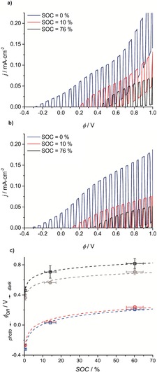
a), b) j−ϕ chopped (1 sun illumination/dark) curves recorded in the PEC cell at different SOC for two representative hematite samples from batch B (four bare and four coated) a) bare b) coated at a recording interval of 5 mV at scan rate of 10 mV s−1. c) Average ϕ on,photo (red and blue) and ϕ on,dark (black and gray) for bare hematite samples (circles) and coated (squares) with standard deviation obtained from the chopped j−ϕ curves recorded in the PEC cell and semi‐logarithmic regressions (see Table 1).
Table 1.
Data for semi‐logarithmic regressions from Figure 4 c.
| Model ϕ on=slope⋅ln(SOC)+b | Slope [mV] | R 2 | Max unbiased SOC [%] |
|---|---|---|---|
| ϕ on,photo—bare | 99 | 0.988 | 9.4 |
| ϕ on,photo—coated | 105 | 0.998 | 12.1 |
| ϕ on,dark—bare | 67 | 0.981 | – |
| ϕ on,dark—coated | 72 | 0.999 | – |
In Figure 5, the absorption of the ferrocyanide side of the PEC fitted with a coated hematite samples left under 1 sun illumination (starting at 0 % SOC) and no voltage bias is shown as a function of time to ensure that the observed photocurrent is inherent to ferricyanide production. An increase in absorption at 420 nm corresponding to the production of ferricyanide indicates that the PEC/RF cell is indeed being solar charged (Supporting Information, Figure S4.2).
Figure 5.
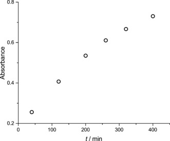
The increasing absorbance of the ferrocyanide/ferricyanide solution at 420 nm in the PEC cell (starting at 0 % SOC) with a coated hematite sample left under 1 sun illumination.
It is clear from Figure 3 that both surface treatments improve the photovoltage, the polyaniline coating most significantly. Low temperature steam annealing has earlier shown improvement in photoelectrochemical response of photoelectrodes due to patching of surface defects.14 It also provides a smoother hematite layer for more homogeneous polyaniline deposition. Polyaniline is a conjugated polymer previously used as a sensitizer in TiO2 photovoltaic devices for its electrical, optical, and photoelectric properties.15, 16 It has also earlier been integrated with a WO3 photoelectrode, changing the photoelectrochemical behavior significantly.17 Recently, ferrocyanide has been studied as a hole‐collector for hematite photoanodes with the aim of elucidating the properties and limitations of hematite photoanodes.2, 13 It was shown that the most important recombination mechanism is back‐electron transfer of the photogenerated electrons into the ferricyanide Fe(CN)6 3−, as illustrated in Figure 1 (red dotted arrow). The photovoltage was found to decrease with increasing ferricyanide concentration in a semi‐logarithmic manner (slope 147 mV) consistent with the semi‐logarithmic fits in Figure 3 b, but with different slopes. This means that 147 mV of photovoltage is lost for every decade increase in ferricyanide concentration, here corresponding to the charged species in the flow battery and thus unavoidable. In Figure 3 b, the photovoltage loss is 122 mV for bare and annealed samples and for the coated hematite sample only 73 mV. Thus, while annealing shifts ϕ on,photo to more negative potentials, it does not change the back‐electron recombination; however, the polyaniline coating does.
An explanation as to why polyaniline actively reduces the back electron recombination with ferrocyanide/ferricyanide is illustrated with Figure 6, which is adapted from a report where a polyaniline coated TiO2 photoelectrode shows increased photodegradation of methylene blue.15 Polyaniline absorbs visible light, since it has a fundamental absorption transition π→π* corresponding to intramolecular charge transfer excitation, at 600 nm.16, 18 This transition is represented in Figure 6 together with the band positions of hematite. The presence of the lowest unoccupied molecular orbital (LUMO), which is more negative in energy than the hematite conduction band, prevents back electron injection to ferrocyanide whilst maintaining a favorable energy step for holes to move from the valence band to the highest occupied molecular orbital (HOMO). For light to be absorbed by hematite, the polyaniline layer had to be very thin so it is hypothesized that some electrons can still tunnel through the polyaniline layer and thus the back electron transfer is not completely inhibited. An optimization of the thickness could further improve this result.
Figure 6.
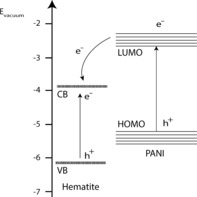
Illustration of a possible mechanism for increased electron harvesting in the hematite‐PANI photoelectrode under visible‐light illumination adapted from Reference [15].
In Figure 4 a and b it is clear that the photocurrent decreases with higher SOC. This is expected, owing to a lower concentration of the hole‐acceptor species (ferrocyanide) and decreasing transparency of the electrolyte. The favorable effect of the polyaniline coating illustrated in Figure 3 is less clear in the PEC/RF cell tests of Figure 4 and Table 1. In Table 1, the slopes of the semi‐logarithmic regressions of around 100 mV for both samples in the light and 70 mV in the dark show the opposite effect of the one observed in Figure 3, though a higher unbiased SOC can be reached for the coated samples. It is attributed to increased ohmic losses in the cell and the overvoltage associated with the AQDS reduction.10 Furthermore, the Nernst contribution to the battery redox potentials shifts the relative positions of ferro/ferricyanide and AQDS further apart. This possibly causes the AQDS half‐cell potential to shift critically close to the conduction band edge of hematite.
Calculating the half‐cell potential for the AQDS side at 99.0 % SOC gives a potential of −0.31 VNHE. Consequently, considering Figure 1, there should still be a favourable potential step for the reduction of around 200 mV, though it is significantly smaller than at, for example, 1.0 % SOC where the AQDS half‐cell potential is −0.19 VNHE indicating a potential step of around 300 mV.
The solar‐to‐chemical‐energy conversion efficiency of the combined system is ca. 0.05–0.08 % (Supporting Information, Figure S5.1). However, the current work is a proof‐of‐principle of a solar charged RFB that is stable, non‐toxic, non‐flammable, and uses low cost and environmentally benign materials. Future investigations in new redox pairs, use of other low‐cost phototoelectrodes such as Cu2O or BiVO4 or tandem photoelectrode systems, which have been widely described, may lead to higher efficiencies and feasible solar charged redox flow batteries.19 For surface treatments, other conducting polymers such as polyacetylene and polyphenylene could be tested with other photoelectrodes in other electrolyte systems.
In summary, it is shown that direct solar charging of an aqueous alkaline ferrocyanide/anthraquinone RFB is possible with a hematite photoanode. It is emphasized that the redox species and photoelectrode are low cost materials and stable under the investigated conditions. Surface treatments of the hematite photoanodes especially with polyaniline have shown improved performance in terms of ferrocyanide oxidation photovoltage. The solar energy storage approach described here opens up many new possibilities with respect to variation of aqueous electrolytes and low band‐gap photoelectrodes. The use of especially organic electrolytes in alkaline, aqueous media offers a wide range of possibilities with respect to tailoring electrochemical properties through manipulation of functional groups.
Supporting information
As a service to our authors and readers, this journal provides supporting information supplied by the authors. Such materials are peer reviewed and may be re‐organized for online delivery, but are not copy‐edited or typeset. Technical support issues arising from supporting information (other than missing files) should be addressed to the authors.
Supplementary
Acknowledgements
This work was supported by the Danish Council for Independent Research, Technology & Production (Grant agreement no. DFF‐4005‐00517). J. Azevedo is grateful to the FCT SFRH/ BD/79207/2011 PhD grant. This work was supported by research project BI‐DSC (grant agreement no. 321315) funded by European Research Council, project POCI‐01‐0145‐FEDER‐006939 (Laboratory for Process Engineering, Environment, Biotechnology and Energy (LEPABE) funded by FEDER through COMPETE2020) and by national funds through FCT (Fundação para a Ciência e a Tecnologia).
K. Wedege, J. Azevedo, A. Khataee, A. Bentien, A. Mendes, Angew. Chem. Int. Ed. 2016, 55, 7142.
Contributor Information
Anders Bentien, Email: bentien@eng.au.dk.
Adélio Mendes, Email: mendes@fe.up.pt.
References
- 1. Yang Z., Zhang J., Kintner-Meyer M., Lu X., Choi D., Lemmon J., Liu J., Chem. Rev. 2011, 111, 3577. [DOI] [PubMed] [Google Scholar]
- 2. Klahr B., Hamann T., J. Phys. Chem. C 2011, 115, 8393. [Google Scholar]
- 3. Krol R. v. d., Grätzel M., Photoelectrochemical hydrogen production, Springer, New York, 2012. [Google Scholar]
- 4. Tilley S., Cornuz M., Sivula K., Gratzel M., Angew. Chem. Int. Ed. 2010, 49, 6405; [DOI] [PubMed] [Google Scholar]; Angew. Chem. 2010, 122, 6549. [Google Scholar]
- 5. Sharon M., Veluchamy P., Natarajan C., Kumar D., Electrochim. Acta 1991, 36, 1107. [Google Scholar]
- 6. Yu M., Ren X., Ma L., Wu Y., Nat. Commun. 2014, 5, 5111; [DOI] [PubMed] [Google Scholar]; Wei Z., Liu D., Hsu C., Liu F., Electrochem. Commun. 2014, 45, 79. [Google Scholar]
- 7. Liu P., Cao Y., Li G., Gao X., Ai X., Yang H., ChemSusChem 2013, 6, 802; [DOI] [PubMed] [Google Scholar]; Yan N., Li G., Gao X., J. Mater. Chem. 2013, 1, 7012. [Google Scholar]
- 8. Gong K., Fang Q., Gu S., Li S., Yan Y., Energy Environ. Sci. 2015, 8, 3515. [Google Scholar]
- 9. Lin K., Chen Q., Gerhardt M., Tong L., Kim S., Eisenach L., Valle A., Hardee D., Gordon R., Aziz M., Marshak M., Science 2015, 349, 1529. [DOI] [PubMed] [Google Scholar]
- 10. Huskinson B., Marshak M., Suh C., Er S., Gerhardt M., Galvin C., Chen X., Aspuru-Guzik A., Gordon R., Aziz M., Nature 2014, 505, 195. [DOI] [PubMed] [Google Scholar]
- 11. Bora D., Braun A., Constable E., Energy Environ. Sci. 2013, 6, 407. [Google Scholar]
- 12. Dotan H., Mathews N., Hisatomi T., Gratzel M., Rothschild A., J. Phys. Chem. Lett. 2014, 5, 3330. [DOI] [PubMed] [Google Scholar]
- 13. Klahr B., Gimenez S., Fabregat-Santiago F., Bisquert J., Hamann T., Energy Environ. Sci. 2012, 5, 7626. [Google Scholar]
- 14. Azevedo J., Steier L., Dias P., Stefik M., Sousa C., Araujo J., Mendes A., Graetzel M., Tilley S., Energy Environ. Sci. 2014, 7, 4044. [Google Scholar]
- 15. Wang F., Min S., Han Y., Feng L., Superlattices Microstruct. 2010, 48, 170. [Google Scholar]
- 16. Molapo K., Ndangili P., Ajayi R., Mbambisa G., Mailu S., Njomo N., Masikini M., Baker P., Iwuoha E., Int. J. Electrochem. Sci. 2012, 7, 11859. [Google Scholar]
- 17. Janáky C., de Tacconi N., Chanmanee W., Rajeshwar K., J. Phys. Chem. C 2012, 116, 4234. [Google Scholar]
- 18. Wallace G., Teasdale P., Spinks G., Kane-Maguire L., Conductive Electroactive Polymers: Intelligent Materials Systems, 2nd ed., CRC Press, Boca Raton, FL, 2002. [Google Scholar]
- 19. Kim J., Magesh G., Youn D., Jang J., Kubota J., Domen K., Lee J., Sci. Rep. 2013, 3, 2681; [DOI] [PMC free article] [PubMed] [Google Scholar]; Paracchino A., Laporte V., Sivula K., Gratzel M., Thimsen E., Nat. Mater. 2011, 10, 456; [DOI] [PubMed] [Google Scholar]; Brillet J., Yum J., Cornuz M., Hisatomi T., Solarska R., Augustynski J., Graetzel M., Sivula K., Nat. Photonics 2012, 6, 824; [Google Scholar]; Abdi F., Han L., Smets A., Zeman M., Dam B., van de Krol R., Nat. Commun. 2013, 4, 2195. [DOI] [PubMed] [Google Scholar]
Associated Data
This section collects any data citations, data availability statements, or supplementary materials included in this article.
Supplementary Materials
As a service to our authors and readers, this journal provides supporting information supplied by the authors. Such materials are peer reviewed and may be re‐organized for online delivery, but are not copy‐edited or typeset. Technical support issues arising from supporting information (other than missing files) should be addressed to the authors.
Supplementary


