Abstract
The thickness of the human tympanic membrane (TM) is known to vary considerably across different regions of the TM. Quantitative determination of the thickness distribution and mapping of the TM is of significant importance in hearing research, particularly in mathematical modeling of middle-ear dynamics. Change in TM thickness is also associated with several middle-ear pathologies. Determination of the TM thickness distribution could therefore also enable a more comprehensive diagnosis of various otologic diseases. Despite its importance, very limited data on human TM thickness distribution, obtained almost exclusively from ex vivo samples, are available in the literature. In this study, the thickness distribution for the in vivo human TM is reported for the first time. A hand-held imaging system, which combines a low coherence interferometry (LCI) technique for single-point thickness measurement, with video-otoscopy for recording the image of the TM, was used to collect the data used in this study. Data were acquired by pointing the imaging probe over different regions of the TM, while simultaneously recording the LCI and concomitant TM surface video image data from an average of 500 locations on the TM. TM thickness distribution maps were obtained by mapping the LCI imaging sites onto an anatomically accurate wide-field image of the TM, which was generated by mosaicking the sequence of multiple small field-of-view video-otoscopy images. Descriptive statistics of the thickness measurements obtained from the different regions of the TM are presented, and the general thickness distribution trends are discussed.
Keywords: tympanic membrane thickness, low coherence interferometry, optical coherence tomography, mosaic, image registration
Introduction
Despite there being a general agreement that the thickness of the human tympanic membrane (TM) varies considerably across different regions of the TM, very limited data on the TM thickness distribution are available in the literature, with all of it from ex vivo specimens. TM thickness distribution is one of the key parameters in mathematical modeling of middle-ear dynamics. Such models play a fundamental role not only in advancing our understanding of the hearing process (Sun et al. 2002; Song and Lee, 2012) but also in designing ear prostheses (Gan et al. 2010). In the absence of adequate data on TM thickness distribution, most mathematical models tend to make overly simplified assumptions regarding the thickness of the TM, in some cases, to the extreme of assuming a single thickness value across the entire membrane. TM thickness also provides valuable information about the state and functioning of the middle-ear and is known to provide diagnostically useful information about several middle-ear pathologies. For example, it has been shown that the thickness of the TM in healthy human subjects is significantly different from the thickness in subjects with acute and chronic otitis media (OM) (Nguyen et al. 2012; Monroy et al. 2015). A reliable method of determining in vivo TM thickness distributions could, therefore, also enable a more comprehensive diagnosis of various otologic diseases.
One of the earliest measurements of human TM thickness was performed by Kojo (1954), who reported a thickness range of 30–120 μm based on measurements performed at seven different locations in seven TMs. Lim (1970) used light microscopy to measure the thicknesses of 20 fixed adult TMs, and reported a range of 30–230 μm for the pars flaccida and 30–90 μm for the pars tensa regions of the TM. Uebo et al. (1988) reported a mean TM thickness value between 67 and 90 μm for ten different sites in 96 normal TMs from 78 subjects of varying age. In another study, Ruah et al. (1991) performed thickness measurements in 46 normal TMs harvested at autopsy from subjects between the ages of 2 days and 91 years using light and electron microscopy. A more systematic imaging approach for characterizing the thickness distribution for the human TM was described by Kuypers et al. (2006), in which the investigators, using confocal microscopy, measured the TM thickness along a line parallel to the manubrium, joining the umbo inferiorly to the annulus, and also along six other lines perpendicular to the manubrium between the superior and inferior ends of the TM. The authors reported a mean thickness range of 40–120 μm in the central region of the three TMs used in the study. More recently, Van der Jeught et al. (2013) used optical coherence tomography (OCT) to obtain full-field thickness distributions for six TMs harvested from human cadavers.
The ability of OCT to provide cellular-level axial resolution over an imaging depth of a few millimeters, in a non-invasive and non-contact manner, makes it an attractive modality for TM imaging. Several recent studies from our group and others have demonstrated the ability of OCT to visualize the TM and the middle-ear structures behind the TM (Pitris et al. 2001; Djalilian et al. 2008; Nguyen et al. 2012; Shelton et al. 2014; Monroy et al. 2015). In particular, an imaging system integrating low coherence interferometry (LCI), which is essentially a non-scanning version of OCT, with a modified video otoscope has been shown to be a simple and promising imaging tool for single-point measurements of in vivo TM thickness (Nguyen et al. 2010, 2012). Typical data acquired by the combined LCI-otoscope system comprises a sequence of images of partial views of the TM and corresponding 1-D depth resolved scattering profiles, obtained from multiple locations on the TM.
In this study, we present an approach to obtain thickness distributions for the in vivo human TM by using data acquired from a combined LCI-otoscope system. TM thickness maps are obtained by mapping the LCI imaging sites onto an anatomically accurate wide-field image of the TM generated by mosaicking the sequence of multiple small field-of-view video-otoscopy images of the TM. We also report descriptive statistics of the thickness measurements obtained from the different regions of the TM and discuss the general trends of TM thickness distribution. This study, to the best of our knowledge, is the first to report full-field thickness distribution measurements for the in vivo human TM.
Materials and Methods
Imaging System and Data Collection
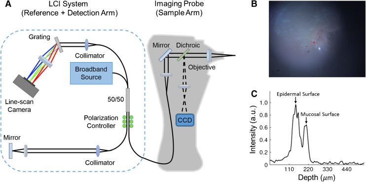
The hand-held Fourier-domain LCI system used in this study was built in-house for clinical imaging. As shown in Figure 1A, the reference and detection arm of the LCI system includes a broadband superluminescent diode (SLD) (Broadlighter S930, Superlum, Ireland), centered at 940 nm wavelength with a bandwidth of approximately 70 nm full width at half maximum (FWHM) as the optical source, and a spectrometer unit (COBRA, Wasatch Photonics, USA) with a spectral range of 940 ± 40 nm and a line rate of up to 40 kHz as the detector. Additional optical components include a 2 × 2 fiber coupler, with polarization paddles on the reference and sample ports of the fiber coupler, and a free-space reference arm with a mirror for reflecting light back into the interferometer.
FIG. 1.
A Schematic of the combined LCI-otoscope imaging system used in the study. B TM surface image, similar to a video-otoscope image, acquired by the CCD camera. C Depth-resolved LCI data acquired at the imaging site marked by the red point in (B). The two prominent peaks correspond to the epidermal and the mucosal surfaces of the TM. TM thickness is estimated as the distance between the two peaks.
The hand-held imaging probe houses the sample arm of the interferometer, along with the optics for video otoscopic imaging. The probe nose-cone was extracted from a commercial otoscope (R.A. Bach Diagnostics, USA) and modified to include a focusing lens. White light is delivered from an LED in the probe housing to the sample via a fiber bundle concentrically arranged at the distal end of the probe nose-cone. The TM surface is imaged onto a miniature camera (MU9PC-MH, Ximea, Germany) using focusing optics located in the handle of the probe. The optical path corresponding to the video imaging (visible) is separated from the LCI imaging path (near-infrared) using a dichroic mirror.
A data-point obtained from the combined LCI-otoscope system comprises a surface image of the TM and corresponding depth-resolved LCI scan data acquired at a fixed point in the field-of-view (FOV) of the surface image, as shown in Figure 1B, C, respectively. The site on the TM from which the LCI data was obtained is marked by a red asterisk in the surface image shown in Figure 1B. The TM thickness at the imaging site was obtained by computing the distance between the two peaks in the LCI data, which correspond to the two layers of the TM, namely, the epidermal (outside) and the mucosal (inside) layers. More specifically, the TM thickness at each imaging site was estimated as the average thickness obtained from a sequence of 100 depth resolved profiles, or A-scans, which were acquired at a rate of 1 kHz. The averaging was performed to provide a more reliable estimate of TM thickness. To obtain the average thickness from a sequence of A-scans, a semi-automated approach was followed in which the multiple 1-D A-scans were first stacked together to build a 2-D M-scan. In the M-scan, the depth information is displayed along the x-axis and the y-axis contains the repeated A-scan measurements. Treating the M-scan as an image, the TM was subsequently segmented by performing an image thresholding operation based on a user-specified threshold level and a region of interest, and the TM thickness was finally obtained as the average thickness of the segmented TM. To account for the path length change introduced by the refractive index (RI) of the TM, based on the RI measurements reported by Van der Jeught et al. (2013), a bulk RI of 1.44 was assumed while estimating the TM thickness from LCI data. Data were acquired from multiple locations on the TM at a rate of 2 data-points per second (surface image and corresponding LCI data) by manually moving and pointing the hand-held imaging probe over different regions of the TM. On average, 500 data-points were acquired from each TM.
Mosaicking Algorithm
Most image mosaicking techniques begin with an assumption of a suitable motion model describing the alignment between a pair of images. The motion model is characterized by a 2-D transformation matrix, which describes the coordinate transformation from one image to the other. Once the motion model is chosen, the parameters of the model are estimated by following either an intensity-based approach or a feature-based approach (Szeliski 2006). In intensity-based methods, the model parameters are estimated by optimizing a suitable similarity metric representing the difference between pixel intensities of an image pair. Commonly used metrics include mean squared error, cross-correlation, or mutual information. Because the metric directly depends on pixel intensity values, these methods are sensitive to image deterioration resulting from various factors such as non-uniform illumination and defocus.
Feature-based techniques rely on matching landmark points between images. In these techniques, a set of matching image features such as edges, corners, or other geometrical structures are first extracted from the images, and subsequently, the optimal image registration parameters are obtained by maximizing a similarity measure computed from the matched features. Some of the more popular feature-matching methods include Scale-Invariant Feature Transform (SIFT) (Lowe 1999) and Speeded Up Robust Features (SURF) (Bay et al. 2006). Unlike intensity-based methods, feature-based methods do not directly depend on the actual pixel values in an image, but rather on image features, which makes these methods more robust to variations in image quality. The performance of feature-based methods, however, largely depends on reliable detection of matched image features, which is challenging in cases when the images lack sharp distinctive features.
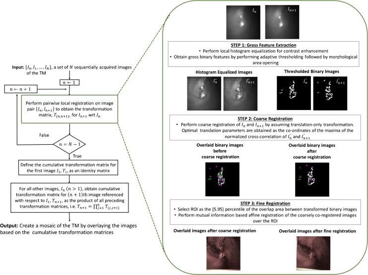
While several image registration techniques have been reported in the biomedical literature, mostly for retinal imaging (Can et al. 2002; Yang and Stewart 2004; Chanwimaluang et al. 2006; Jupeng et al. 2008; Li et al. 2011), these techniques are not directly applicable to TM image mosaicking for two main reasons. First, unlike retinal images, which have several distinctive features such as the bifurcations and crossovers of the blood vessels, TM images predominantly contain large homogeneous, non-vascularized regions lacking in sharp features. Second, due to the specular nature of the TM, the spatial distribution of intensity both within and between surface images of the TM is very heterogeneous depending on the angle and distance of the imaging probe. To address these challenges of TM image mosaicking, we developed a novel two-step mosaicking algorithm, wherein a coarse image registration based on the correlation of gross image features is followed by a finer intensity-based coregistration process. In the following, we describe the various steps of the proposed algorithm, which are also outlined in the flowchart shown in Figure 2.
FIG. 2.
Flowchart describing the processing steps of the proposed mosaicking algorithm.
The proposed mosaicking procedure begins with pairwise registration of consecutive pairs of images. As shown in the dashed box in Figure 2, the pairwise local registration process was performed in three steps. In the first two steps, a coarse feature-based registration of the two images was performed. For reliable image registration in the presence of imaging artifacts such as non-uniform illumination and blurring, which are inevitably present in images acquired from a hand-held imaging probe, only binary features were used for performing the coarse registration. To further mitigate the effect of the aforementioned imaging artifacts, an adaptive thresholding technique, preceded by local histogram equalization for contrast enhancement (Gonzalez et al. 2010) and followed by morphological area opening (Soille 2013) to get rid of insignificant spurious features, was used to extract the binary features from the images (step 1 in Fig. 2). After extracting the binary features from the two images constituting the image pair, in step 2, the coarse registration of the images was performed by assuming a translation-only transformation model. The optimal translation parameters of the model were obtained as the coordinates of the maxima of the normalized cross-correlation of the two binary images obtained in the feature extraction step. Finally, in step 3, an intensity-based finer registration of the coarsely registered images was performed. As mentioned earlier, in intensity-based image registration, a similarity metric based on the image pixel values is optimized to estimate the parameters of the transformation matrix.
In the proposed algorithm, an affine transformation was chosen as the motion model and the parameters of the transformation matrix were estimated by optimizing the mutual information (MI) between the two images. MI is a metric that measures the dependence between two random variables. In image processing, MI is used as a measure of similarity between two images based on the individual and joint image histograms of the two images. As a measure of image similarity, MI is perhaps one of the most widely used measure for performing image registration because of its desirable properties such as robustness to the presence of outliers and efficient computation. For improved convergence, the finer registration was performed only over a region of interest (ROI) that contains significant features. This ROI was identified as the area bounded by the 5th and 95th percentile of the coordinates of the region of overlap between the two coarsely registered binary images obtained from the previous step.
As shown in the flowchart in Figure 2, the process of pairwise registration is iteratively performed for all image pairs starting from the first image, which is also assumed to be the reference image. Denoting the transformation matrix characterizing the coordinate transformation between the image pair {In, In + 1} by T{n,n + 1}, the transformation matrix between a particular image In + 1 referenced with respect to the first image is then obtained by concatenating the preceding pairwise transformation matrices, i.e., Tn + 1 = Πnj = 1T{j,j + 1}. The concatenation process provides a means of mapping the individually coregistered images in their local coordinate system to the mosaic coordinate system.
While the aforementioned mosaicking approach works well for a small set of images, in cases where a large number of images have to be coregistered, the concatenation of the pairwise transformation matrices results in an accumulation of errors leading to global alignment errors in the final mosaic (Capel 2004; Szeliski 2006). This problem is of greater concern for a sequence of images that loops around, re-visiting parts of the imaging scene multiple times at different time points. This is a well-known and well-studied problem in computer vision and various methods to overcome this problem have been reported in the literature. In the current proof-of-concept study, we follow a very simple approach, wherein the sequence of images was manually divided into smaller subsequences of images, which were combined to create submosaics following the mosaicking procedure described earlier. The same mosaicking process was subsequently applied to the submosaics to obtain the final mosaic.
The final step in generating a mosaic is to blend the individual images constituting the mosaic to remove the edges or seams which can occur due to significant differences in brightness and contrast between images. A simple image blending approach was used in this study, in which the pixels corresponding to the overlapping regions between a pair of images in the mosaic were assigned the maximum pixel value of the two images.
Since the spatial coordinates of the LCI beam are the same for each surface image, the spatial locations of the points on the TM where the LCI data were acquired could be tracked by using the same coordinate transformation matrices that are used to generate the mosaic. Consequently, once all the surface images are registered, the locations corresponding to the LCI imaging sites were readily identified and marked on the full-field mosaic of the TM. Because the LCI measurements were performed only at 500 points (on average) on the TM, it was not possible to generate a “true” thickness map for the entire TM. However, treating the thickness measurements at various points on the TM as scattered data and assuming that the thickness varies smoothly over the entire surface of the TM, scattered data interpolation techniques can be employed to obtain a representative thickness distribution map. One such interpolation algorithm based on penalized least squares regression, proposed by Wang et al. (2012), was used in our study to generate the TM thickness distribution maps.
Subject Recruitment and Enrollment
Subjects for this study were recruited and enrolled under a protocol approved by the Institutional Review Boards (IRB) of the University of Illinois at Urbana-Champaign and Carle Foundation Hospital, Urbana, Illinois. The subjects were recruited from and imaged in the Biophotonics Imaging Laboratory at the University of Illinois at Urbana-Champaign. A total of seven TMs from six human volunteers were imaged for this study. Subjects’ ages ranged from 22 to 37 years.
Results
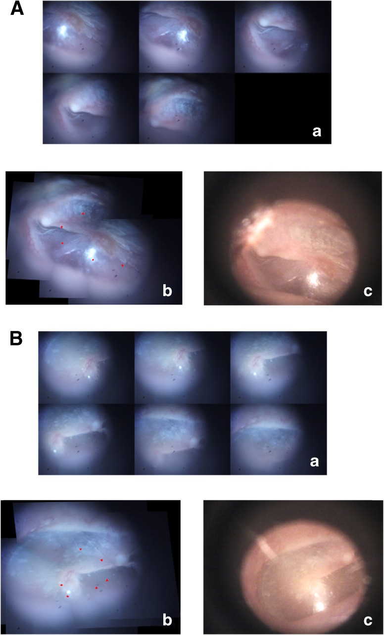
The proposed algorithm was first validated on a smaller sequence of two in vivo TM images acquired from two subjects. The validation results from the two subjects are displayed in Figure 3A and B. Panel a in Figure 3A and B shows the sequence of the small FOV images covering different regions of the two TMs. The mosaics generated from these images by using the proposed technique are shown in panel b. The red markers on the mosaicked images correspond to locations of the LCI beam as the imaging probe was moved across the TM surface to image different locations on the TM. For comparison, the TM images acquired using a commercial video-otoscope (Welch Allyn Digital MacroView) are displayed in panel c.
FIG. 3.
Validation results of the mosaicking algorithm from two subjects, shown in (A) and (B). (a) Montage showing the sequence of TM images acquired during the imaging process. (b) Wide FOV mosaic image obtained using the mosaicking algorithm. (c) Corresponding video-otoscope image of the TM, shown for comparison.
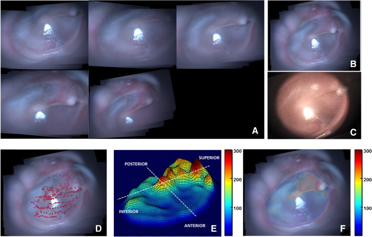
Post-validation, the mosaicking technique was applied to data obtained from imaging four healthy in vivo TMs (TM1–TM4). Figure 4 shows the results of the various steps of the mosaicking process for TM1. As described earlier, several submosaics were combined to obtain a globally consistent mosaic. Figure 4A shows the submosaics obtained by using the proposed algorithm, which were subsequently mosaicked to form the final mosaic shown in Figure 4B. As can be seen, the mosaic in Figure 4B provides a complete view of the TM, which matches well with the video-otoscope image shown in Figure 4C. In Figure 4D, the red points plotted on top of the mosaicked image indicate the locations of the LCI beam, as the probe was moved across the surface of the TM for acquiring data. The thickness values obtained from the LCI data acquired at the locations marked by red points in Figure 4D were used to obtain an interpolated representative thickness distribution map of the TM, which is shown in Figure 4E as a surface plot to better visualize the relative thickness of the different regions of the TM. Finally, Figure 4F shows the coregistered thickness distribution map overlaid on the mosaic image for better interpretation of the thickness data.
FIG. 4.
Mosaicking results for TM1. A Montage showing the sequence of TM images acquired during the imaging process. B Wide FOV mosaic obtained using the mosaicking algorithm. C Corresponding video-otoscope image of the TM. D LCI imaging sites plotted as red points over the mosaicked image. E Thickness distribution map shown as a surface plot (thickness values in μm). F Thickness distribution map overlaid on the mosaicked image (thickness values in μm).
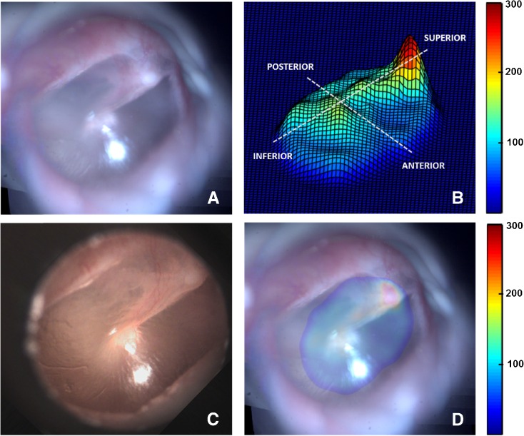
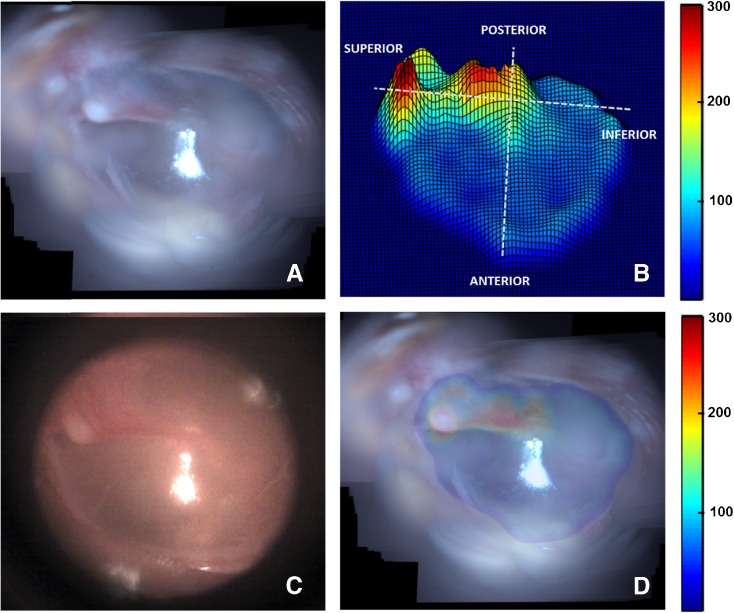
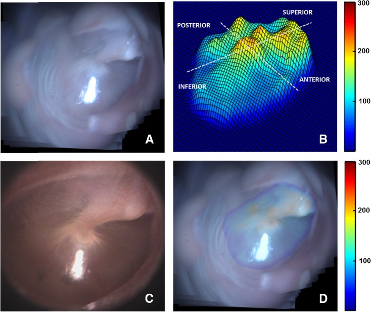
Likewise, the results obtained from TM samples TM2–TM4 are presented in Figures 5, 6, and 7. Panel A in each of these figures shows the mosaicked image of the TM. The video-otoscope image of the TM is shown in panel C for comparison. Panels B and D in each of these figures show the thickness distribution map and the overlay image of the thickness distribution map and the mosaic image, respectively. The thickness distribution maps for all cases show a region of relatively large thickness starting at the umbo and extending along the manubrium to include the pars flaccida and the posterior fold at the superior end of the TM. This thicker region is surrounded by a thinner pars tensa region of the TM. Moreover, an increase in thickness around the annular ring surrounding the pars tensa region is also visible in the surface plots of the thickness distribution maps shown in panel B of the images. These general thickness distribution trends agree with the trends expected in a healthy TM.
FIG. 5.
Mosaicking results for TM2. A Mosaicked TM image. B Thickness distribution map shown as a surface plot (thickness values in μm). C Corresponding video-otoscope image of the TM. D Thickness distribution map overlaid on the mosaicked image (thickness values in μm).
FIG. 6.
Mosaicking results for TM3. A Mosaicked TM image. B Thickness distribution map shown as a surface plot (thickness values in μm). C Corresponding video-otoscope image of the TM. D Thickness distribution map overlaid on the mosaicked image (thickness values in μm).
FIG. 7.
Mosaicking results for TM4. A Mosaicked TM image. B Thickness distribution map shown as a surface plot (thickness values in μm). C Corresponding video-otoscope image of the TM. D Thickness distribution map overlaid on the mosaicked image (thickness values in μm).
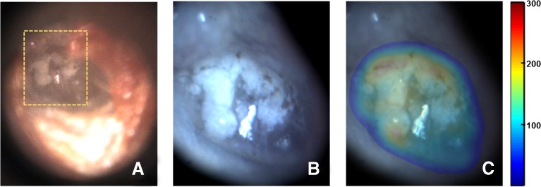
To demonstrate the potential application of the proposed technique in clinical diagnosis, the TM of a subject with tympanosclerosis was imaged. The video-otoscope image of the TM, shown in Figure 8A, shows a white chalky patch with irregular boundaries, a typical presentation of tympanosclerosis. Figure 8B shows the mosaic obtained from images acquired over the region of interest shown by the orange dashed box in Figure 8A, and the corresponding thickness distribution map overlaid on top of the mosaic is shown in Figure 8C. The overlay image clearly shows that the white chalky, scarred region of the TM, which covers a significant part of the pars tensa region, has a thickness much higher than the thickness values typically expected for the pars tensa in healthy TMs (Figs. 4--7).
FIG. 8.
Mosaicking results for a TM with tympanosclerosis. A Video-otoscope image of the TM showing a chalky white patch with irregular boundaries, characteristic of tympanosclerosis. B Mosaicked image obtained over the region enclosed by orange dashed box in (A). C Thickness distribution map overlaid on the mosaicked image (thickness values in μm).
The quantitative thickness measurements are reported in Table 1 for different anatomical regions of the TM. The different regions, namely, the pars flaccida and the four quadrants of the pars tensa, were manually identified and the thickness statistics for each region were computed from the measurements obtained from the imaged sites in the corresponding regions. Moreover, to ensure that only sites from the pars flaccida and pars tensa were used in the analysis, the region around the umbo, the manubrium of the malleus, and the anterior and posterior folds were excluded while selecting the various regions of the TM.
TABLE 1.
Descriptive statistics of thickness measurements of TM1–TM4, grouped by different regions of the TM
| Sample | Number of Measurements | Min (microns) | Max (microns) | Mean (microns) | SD (microns) |
|---|---|---|---|---|---|
| Pars flaccida | |||||
| TM1 | 19 | 113.9 | 236.6 | 191.5 | 35.0 |
| TM2 | 26 | 100.0 | 339.1 | 175.0 | 75.6 |
| TM3 | 12 | 104.0 | 332.4 | 170.0 | 60.6 |
| TM4 | 28 | 115.8 | 206.9 | 163.4 | 23.4 |
| Posterosuperior | |||||
| TM1 | 11 | 76.1 | 257.2 | 152.7 | 60.1 |
| TM2 | 32 | 73.6 | 168.9 | 104.7 | 24.0 |
| TM3 | 15 | 73.5 | 370.0 | 200.8 | 93.4 |
| TM4 | 17 | 89.5 | 248.2 | 134.4 | 54.3 |
| Posteroinferior | |||||
| TM1 | 41 | 62.1 | 162.9 | 105.9 | 20.7 |
| TM2 | 6 | 81.0 | 136.0 | 115.5 | 20.0 |
| TM3 | 57 | 57.7 | 175.9 | 79.8 | 18.3 |
| TM4 | 21 | 75.4 | 208.5 | 99.7 | 39.6 |
| Anterosuperior | |||||
| TM1 | 97 | 47.5 | 195.5 | 74.8 | 23.1 |
| TM2 | 46 | 50.6 | 91.6 | 70.2 | 8.9 |
| TM3 | 42 | 40.0 | 80.1 | 58.0 | 10.2 |
| TM4 | 95 | 50.0 | 205.5 | 89.3 | 24.5 |
| Anteroinferior | |||||
| TM1 | 162 | 33.3 | 147.1 | 82.6 | 26.0 |
| TM2 | 14 | 68.8 | 150.0 | 93.7 | 24.5 |
| TM3 | 138 | 42.5 | 92.2 | 66.4 | 9.5 |
| TM4 | 50 | 60.4 | 130.2 | 99.4 | 17.5 |
| Complete pars tensa | |||||
| TM1 | 311 | 33.3 | 257.2 | 85.7 | 30.7 |
| TM2 | 98 | 50.6 | 168.9 | 87.6 | 24.8 |
| TM3 | 252 | 40.0 | 370.0 | 76.0 | 40.8 |
| TM4 | 183 | 50.0 | 248.2 | 97.4 | 31.4 |
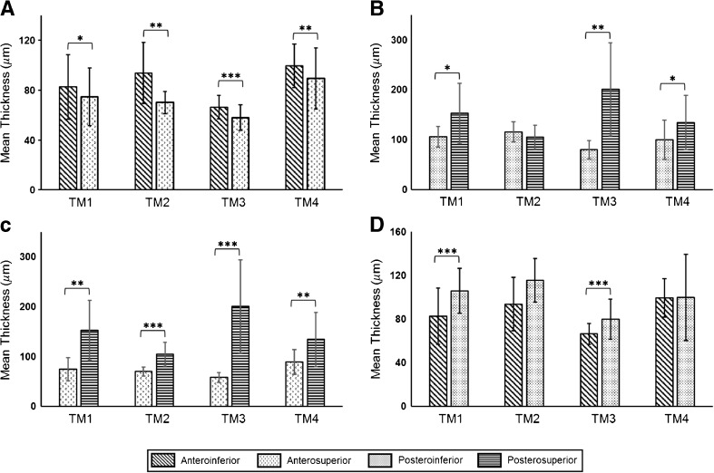
As expected, the pars flaccida was found to be significantly thicker than the pars tensa. The ratio of the mean thickness of pars flaccida to the mean thickness of pars tensa was computed to be 2.2 for TM1, 2.0 for TM2, 2.2 for TM3, and 1.7 for TM4. The mean and pooled standard deviation of the thickness of the pars tensa for all TM samples was found to be 85.6 ± 33.6 μm. The mean and pooled standard deviation of thickness of the different regions of the TM, computed over all TMs, were found to be 137.7 ± 56.1 μm for the posterosuperior quadrant, 93.4 ± 23.9 μm for the posteroinferior quadrant, 76.4 ± 20.5 μm for the anterosuperior quadrant, and 79.2 ± 20.0 μm for the anteroinferior quadrant. Amongst the different quadrants of the pars tensa, the overall mean thickness of the posterosuperior quadrant was found to be higher than the other quadrants. Likewise, the anterosuperior quadrant had the lowest overall mean thickness. The mean thicknesses of the quadrant pairs of the four regions of the pars tensa, namely, anterior, posterior, superior, and inferior, were compared for each TM sample by means of an unpaired two-sided unequal variances t test. The comparison results are shown in Figure 9, along with Table 2, which presents a summary of the results of the statistical analysis. As can be seen in Figure 9, in the anterior region, the inferior side was found to be thicker than the superior side (Fig. 9A), a trend that was reversed in the posterior region, where the superior side was, in general, thicker than the inferior side (Fig. 9B). Likewise, as shown in Figure 9C, the posterior side was found to be thicker than the anterior side in both the superior and inferior regions. Moreover, the difference between the anterior and posterior sides was more marked in the superior region (Fig. 9C) as compared to the inferior region (Fig. 9D), which suggests a larger asymmetry in thickness distribution in the superior region of the TM.
FIG. 9.
Comparison of the mean thicknesses of the quadrants of the anterior, posterior, superior, and inferior regions of the TM, shown in (A–D), respectively, for TM1–TM4. Bars indicate standard deviation. Statistical significance was tested by means of a two-sided unequal variances t test (*p < 0.05, **p < 0.01, ***p < 0.0001).
TABLE 2.
Summary of results of statistical analysis, comparing the thicknesses of the quadrants of the anterior, posterior, superior, and inferior regions of the TM for TM1–TM4
| Sample | Anterior | Posterior | Superior | Inferior | |
|---|---|---|---|---|---|
| AI-AS | PI-PS | AS-PS | AI-PI | ||
| TM1 | t | 2.51 | 2.54 | 4.26 | 6.09 |
| df | 221.0 | 11.0 | 10.0 | 75.0 | |
| p value | 0.0129 | 0.0280 | 0.0015 | <0.0001 | |
| TM2 | t | 3.52 | 1.17 | 7.77 | 2.08 |
| df | 14.0 | 8.0 | 37.0 | 12.0 | |
| p value | 0.0034 | 0.2744 | <0.0001 | 0.0600 | |
| TM3 | t | 4.75 | 4.99 | 5.91 | 5.24 |
| df | 64.0 | 14.0 | 14.0 | 69.0 | |
| p value | <0.0001 | 0.0002 | <0.0001 | <0.0001 | |
| TM4 | t | 2.86 | 2.20 | 3.36 | 0.03 |
| df | 130.0 | 29.0 | 17.0 | 23.0 | |
| p value | 0.0049 | 0.0358 | 0.0036 | 0.9737 |
Statistical significance was tested by means of a two-sided unequal variances t test
AI anteroinferior, AS anterosuperior, PI posteroinferior, PS posterosuperior
Discussion
In this study, we developed an approach for characterizing the thickness distribution for the in vivo human TM. At the core of our approach is a novel image mosaicking algorithm for generating a full-field surface image of the TM with a coregistered thickness map from a sequence of TM surface images and corresponding LCI data obtained using a combined LCI-otoscope imaging system. We obtained thickness distribution maps in vivo for four healthy human TMs and one TM with tympanosclerosis. We observed large intra- and inter-sample variations in TM thickness. The range of the thickness values for the pars flaccida region of the healthy TMs was found to be 76.1–339.1 μm, whereas the thickness of the pars tensa ranged from 33.3 to 248.2 μm. The variability observed in our study is in agreement with the findings of several previously published studies (Lim 1970; Uebo et al. 1988; Ruah et al. 1991; Kuypers et al. 2006). The wide range of TM thickness underlines the importance of characterizing and taking into account the variability in thickness distribution for the TM for accurate modeling of middle-ear dynamics and analysis of the results obtained thereof.
While substantial variation in both the overall thickness and the thickness of different regions of the TM was observed, some similarities in the thickness distribution trends were noted. The pars flaccida was in general thicker than the pars tensa in all TM samples, an observation also made by Lim (1970) and Ruah et al. (1991). In the pars tensa, the overall mean thickness of the posterosuperior quadrant was found to be higher than those of the other quadrants. A similar finding was reported by Uebo et al. (1988) and Ruah et al. (1991). Moreover, as reported by Van der Jeught et al. (2013), and confirmed in our study, the variance in thickness of the posterosuperior quadrant was found to be higher than those of the other quadrants. It is interesting to note that the surface plots of the thickness distribution maps of the healthy TM samples show a ridge at the light reflex of the TM, which corresponds to a localized region of higher thickness. This observation concurs with the findings of Kuypers et al. (2006) and Van der Jeught et al. (2013), where a local thickening in the anteroinferior quadrant of the TM was observed. Moreover, as pointed out in several previously published studies, and confirmed by the results of our study, the thickness distribution inferior to the umbo was found to be symmetric between the anterior and posterior side, whereas it becomes more asymmetric in the superior part of the TM. The mean thickness of the pars tensa ranged from 76.0 to 97.4 μm, which is similar to the typical values used by researchers in finite element modeling of the TM (Wada et al. 1992; Koike et al. 2002; Volandri et al. 2011).
It must be emphasized that as noted above, and in several previous studies, the thickness values obtained for the different regions of the TM depend markedly on various factors such as the anatomical variations and ages of the subjects (Ruah et al. 1991) and the choice of the measurement sites. Therefore, the thickness values reported in our study and the comparisons made with other studies should be interpreted as general trends, rather than as absolute quantitative results. It is also important to point out that, while estimating the thickness of the TM from LCI data, it was assumed that the imaging beam was normally incident on the TM. In practice, the angle between the imaging beam and the TM depends on a multitude of factors. While some of these factors, such as the angle of the TM with respect to the external ear canal, can be quantitatively accounted for based on the average values reported in the literature (Ikui et al. 1997; Todd 2009), other factors, such as the geometry of the ear canal, and the angle of the probe with respect to the TM, which depend on both the subject being imaged and the imaging conditions (probe orientation etc.), are extremely difficult to quantify reliably. The assumption of normal incidence, therefore, provides a potential source of error in our thickness estimates. More specifically, if the TM has an angular tilt of θ along the axis perpendicular to the imaging beam, then the thickness of the TM based on LCI data is overestimated by a factor of 1/cos θ. The inability to determine the angle between the imaging beam and the TM, in our study, results primarily from the absence of a lateral scanning mechanism in our imaging probe. The choice of not incorporating a lateral scanning mechanism in our handheld probe was guided by the need to provide a low-cost imaging solution for TM thickness mapping. Nevertheless, to mitigate the angle-related error in thickness measurements, a lateral scanning scheme could be incorporated in our hand-held probe design to obtain B-scans of the TM. The 2-D cross-sectional depth-resolved scans of the TM could then be used to reliably obtain thickness measurements, even in the case when the TM is not exactly perpendicular to the imaging beam (Hubler et al. 2015). An alternative method of correcting for geometric and refractive distortions could involve using sophisticated ray-tracing-based methods (Westphal et al. 2002, Ortiz et al. 2010). The correction methods based on lateral scanning would, however, impose stringent requirements on stability during data acquisition, which would be extremely challenging, if not impossible, to achieve in in vivo imaging applications based on hand-held probes. Moreover, incorporating a microelectromechanical systems (MEMS) scanner in a hand-held imaging probe to enable lateral scanning would also significantly increase the cost of the imaging system.
Another potential source of variability in thickness estimation arises from the semi-automated approach used to obtain the average thickness of the TM. As described earlier in this article, the semi-automated approach relies on a user-specified threshold value for the segmentation of the TM in an M-scan. Due to the inherent noise in each A-scan, using a single threshold value for an M-scan introduces variability in thickness estimation. Based on the results of a simulation study, where a plastic sheet of uniform thickness, used as a TM phantom, was imaged using our imaging probe, we found the variability in thickness estimation to be less than 10 %. This level of variability is acceptable for most diagnostic purposes, such as for the differentiation of otitis media (OM), where the difference in thickness between a normal TM and a TM with acute or chronic OM is usually on the order of 100–200 % (Monroy et al. 2015).
Though this study presents an important proof-of-concept approach to obtain thickness distribution maps of the in vivo human TM, some limitations exist that warrant discussion. First, an affine model for camera motion was assumed for image registration in this study. While this assumption is perhaps not overly restrictive, it might not be strictly satisfied while imaging the peripheral regions of the TM, where the curvature of the TM, combined with significant tilt and pan of the hand-held probe to enable imaging, may introduce projective distortion in the images. In such cases, a more accurate, albeit computationally more demanding, projective motion model might be more appropriate.
Second, the selection of the submosaics in the global registration step of the proposed approach was performed based on visual assessment of the submosaics. To automate this step, an approach similar to that described by Mann and Picard (1997) could be followed, where the choice of the submosaics is determined by computing the local minima of the mean-squared registration error. Likewise, more sophisticated techniques for image blending such as Laplacian pyramidal blending and gradient domain blending (Szeliski 2006) could also be used.
Third, it must be pointed out that an average of about 26 % of the acquired images and corresponding LCI data were manually excluded from this study because of their low quality. Figure 10 shows representative examples of such images. Figure 10A shows an example of an image where a significant portion of the FOV was occluded by the ear canal, which appears as an off-center diffused hazy region in the image. The image shown in panel B of the figure shows an example of an image that contains a featureless region of the TM and is therefore not suitable for image registration. A possible way to automate the exclusion of these two types of image could be to set a threshold in the pairwise local registration step of the mosaicking algorithm (step 1 in Fig. 2) to determine whether enough features are present in the image for it to qualify as a suitable image for mosaicking. The third type of image that was excluded from the study, an example of which is shown in Figure 10C, comprised images that were severely defocused. This defocus blur can be mitigated by improving the camera optics to achieve greater depth-of-focus, thereby allowing for blur-free imaging over a wider range of probe-to-TM distances.
FIG. 10.
Representative examples of poor quality images that were excluded from the study. A An image where a significant portion of the FOV is occluded by the ear canal. B Example of an image that contains a featureless region of the TM. C A severely defocused image.
Finally, as stated earlier, the current imaging system has a rather limited acquisition rate of 2 data-points per second. It must be emphasized though that this limited acquisition rate is a result of the delay that had to be introduced between the acquisition of successive data-points to circumvent a certain software-hardware synchronization issue and not because of a slow A-line acquisition rate, which was 1 kHz, or CCD image read-out rate, which was approximately 6 fps. In other words, while each data-point was acquired at an effective rate of 2 data-points per second, the measurements constituting the data-point were acquired at the much faster rates of 1 kHz (for LCI data) and 6 fps (for CCD images), thereby not imposing any strict stability requirements during imaging. In fact, in our study, no special procedure was followed to restrict either the subject or operator movement during data acquisition, other than what would be required during a standard otoscopic examination in a typical clinical setting. Nevertheless, eliminating the delay between the acquisition of successive data-points and using a faster CCD camera could significantly reduce the imaging time.
Conclusion
The present study developed an approach to obtain, for the first time, thickness distribution maps for the in vivo human TM. The data used in our study were acquired from a hand-held imaging system combining LCI for single-point thickness measurements with video imaging for recording the surface images of the TM as the imaging probe is moved and directed across the membrane. We envision that the proposed approach has the potential to not only provide useful information for advancing our fundamental understanding of the functioning of the middle-ear, through experiments and modeling, but could also provide significant diagnostic information in the form of normative TM thickness distribution maps, much like the retinal thickness maps (Zeimer 1998; Jaffe and Caprioli 2004) that are routinely used in ophthalmological disease diagnosis and treatment.
Acknowledgments
The authors thank Darold Spillman and Eric Chaney from the Beckman Institute for the helpful discussions and for IRB support, respectively. This work was supported in part by grants from the National Institutes of Health, Bioengineering Research Partnership NIBIB, R01 EB013723, and from the National Science Foundation, EAGER CBET 14-45111. Additional information can be found at http://biophotonics.illinois.edu.
Compliance with Ethical Standards
Conflict of Interest
R.L.S., R.M.N., and S.A.B. have a financial interest in PhotoniCare, Inc. PhotoniCare did not, however, sponsor this research. The remaining authors do not have any conflict of interest.
References
- Bay H, Tuytelaars T, Van Gool L (2006) SURF: Speeded Up Robust Features. In: Computer Vision–ECCV 2006. Springer, pp 404–417
- Can A, Stewart CV, Roysam B, Tanenbaum HL. A feature-based, robust, hierarchical algorithm for registering pairs of images of the curved human retina. IEEE Trans Pattern Anal Mach Intell. 2002;24(3):347–364. doi: 10.1109/34.990136. [DOI] [Google Scholar]
- Capel D (2004) Image mosaicing and super-resolution. Springer Science & Business Media
- Chanwimaluang T, Fan G, Fransen SR. Hybrid retinal image registration. IEEE Trans Inf Technol Biomed. 2006;10(1):129–142. doi: 10.1109/TITB.2005.856859. [DOI] [PubMed] [Google Scholar]
- Djalilian HR, Ridgway J, Tam M, Sepehr A, Chen Z, Wong BJ (2008) Imaging the human tympanic membrane using optical coherence tomography in vivo. Otol Neurotol 29(8):1091--1094 [DOI] [PMC free article] [PubMed]
- Gan RZ, Dai C, Wang X, Nakmali D, Wood MW. A totally implantable hearing system–design and function characterization in 3D computational model and temporal bones. Hear Res. 2010;263(1):138–144. doi: 10.1016/j.heares.2009.09.003. [DOI] [PubMed] [Google Scholar]
- Gonzalez RC, Woods RE, Eddins SL (2010) Digital image processing using MATLAB®. Tata McGraw Hill Education
- Hubler Z, Shemonski ND, Shelton RL, Monroy GL, Nolan RM, Boppart SA (2015) Real-time automated thickness measurement of the in vivo human tympanic membrane using optical coherence tomography. Quant Imaging Med Surg 5(1):69--77 [DOI] [PMC free article] [PubMed]
- Ikui A, Sando I, Sudo M, Fujita S (1997) Postnatal change in angle between the tympanic annulus and surrounding structures. Computer-aided three-dimensional reconstruction study. Ann Otol Rhinol Laryngol 106(1):33–36 [DOI] [PubMed]
- Jaffe GJ, Caprioli J. Optical coherence tomography to detect and manage retinal disease and glaucoma. Am J Ophthalmol. 2004;137(1):156–169. doi: 10.1016/S0002-9394(03)00792-X. [DOI] [PubMed] [Google Scholar]
- Jupeng L, Houjin C, Chang Y, Xinyuan Z (2008) A robust feature-based method for mosaic of the curved human color retinal images. In: Proceedings of the IEEE International Conference on Biomedical Engineering and Informatics. vol 1, pp 845–849
- Koike T, Wada H, Kobayashi T. Modeling of the human middle ear using the finite-element method. J Acoust Soc Am. 2002;111(3):1306–1317. doi: 10.1121/1.1451073. [DOI] [PubMed] [Google Scholar]
- Kojo Y. Morphological studies of the human tympanic membrane. J Otorhinolaryng Soc Jap. 1954;57(2):115–126. [Google Scholar]
- Kuypers LC, Decraemer WF, Dirckx JJ. Thickness distribution of fresh and preserved human eardrums measured with confocal microscopy. Otol Neurotol. 2006;27(2):256–264. doi: 10.1097/01.mao.0000187044.73791.92. [DOI] [PubMed] [Google Scholar]
- Li Y, Gregori G, Lam BL, Rosenfeld PJ (2011) Automatic montage of SD-OCT data sets. Opt Express 19(27):26239–26248 [DOI] [PMC free article] [PubMed]
- Lim D. Human tympanic membrane: an ultrastructural observation. Acta Otolaryngol. 1970;70(3):176–186. doi: 10.3109/00016487009181875. [DOI] [PubMed] [Google Scholar]
- Lowe DG (1999) Object recognition from local scale-invariant features. In: The Proceedings of the Seventh IEEE International Conference on Computer Vision, vol 2, pp 1150–1157
- Mann S, Picard RW. Video orbits of the projective group a simple approach to featureless estimation of parameters. IEEE Trans Image Process. 1997;6(9):1281–1295. doi: 10.1109/83.623191. [DOI] [PubMed] [Google Scholar]
- Monroy GL, Shelton RL, Nolan RM, Nguyen CT, Novak MA, Hill MC, McCormick DT, Boppart SA (2015) Noninvasive depth-resolved optical measurements of the tympanic membrane and middle ear for differentiating otitis media. The Laryngoscope 125(8):E276–282 [DOI] [PMC free article] [PubMed]
- Nguyen CT, Tu H, Chaney EJ, Stewart CN, Boppart SA. Non-invasive optical interferometry for the assessment of biofilm growth in the middle ear. Biomed Opt Express. 2010;1(4):1104–1116. doi: 10.1364/BOE.1.001104. [DOI] [PMC free article] [PubMed] [Google Scholar]
- Nguyen CT, Jung W, Kim J, Chaney EJ, Novak M, Stewart CN, Boppart SA. Noninvasive in vivo optical detection of biofilm in the human middle ear. Proc Natl Acad Sci. 2012;109(24):9529–9534. doi: 10.1073/pnas.1201592109. [DOI] [PMC free article] [PubMed] [Google Scholar]
- Ortiz S, Siedlecki D, Grulkowski I, Remon L, Pascual D, Wojtkowski M, Marcos S. Optical distortion correction in optical coherence tomography for quantitative ocular anterior segment by three-dimensional imaging. Opt Express. 2010;18(3):2792–2796. doi: 10.1364/OE.18.002782. [DOI] [PubMed] [Google Scholar]
- Pitris C, Saunders KT, Fujimoto JG, Brezinski ME. High-resolution imaging of the middle ear with optical coherence tomography: a feasibility study. Arch Otolaryngol Head Neck Surg. 2001;127(6):637–642. doi: 10.1001/archotol.127.6.637. [DOI] [PubMed] [Google Scholar]
- Ruah CB, Schachern PA, Zelterman D, Paparella MM, Yoon TH. Age-related morphologic changes in the human tympanic membrane: a light and electron microscopic study. Arch Otolaryngol Head Neck Surg. 1991;117(6):627–634. doi: 10.1001/archotol.1991.01870180063013. [DOI] [PubMed] [Google Scholar]
- Shelton RL, Jung W, Sayegh SI, McCormick DT, Kim J, Boppart SA. Optical coherence tomography for advanced screening in the primary care office. J Biophotonics. 2014;7(7):525–533. doi: 10.1002/jbio.201200243. [DOI] [PMC free article] [PubMed] [Google Scholar]
- Soille P (2013) Morphological Image Analysis: Principles and Applications. Springer Science & Business Media
- Song YL, Lee CF. Computer-aided modeling of sound transmission of the human middle ear and its otological applications using finite element analysis. Tzu Chi Med J. 2012;24(4):178–180. doi: 10.1016/j.tcmj.2012.08.004. [DOI] [Google Scholar]
- Sun Q, Gan R, Chang KH, Dormer K. Computer-integrated finite element modeling of human middle ear. Biomech Model Mechanobiol. 2002;1(2):109–122. doi: 10.1007/s10237-002-0014-z. [DOI] [PubMed] [Google Scholar]
- Szeliski R. Image alignment and stitching: a tutorial. Found Trends Comp Graphics and Vision. 2006;2(1):1–104. doi: 10.1561/0600000009. [DOI] [Google Scholar]
- Todd NW. Tympanum-canal angles anteriorly, anteroinferiorly, and inferiorly: a postmortem study of 41 adult crania. ENT. Ear Nose Throat J. 2009;88(9):E22–E27. [PubMed] [Google Scholar]
- Uebo K, Kodama A, Oka Y, Ishii T. Thickness of normal human tympanic membrane. Ear Res Jap. 1988;19:70–73. [Google Scholar]
- Van der Jeught S, Dirckx JJ, Aerts JR, Bradu A, Podoleanu AG, Buytaert JA. Full-field thickness distribution of human tympanic membrane obtained with optical coherence tomography. J Assoc Res Otolaryngol. 2013;14(4):483–494. doi: 10.1007/s10162-013-0394-z. [DOI] [PMC free article] [PubMed] [Google Scholar]
- Volandri G, Di Puccio F, Forte P, Carmignani C. Biomechanics of the tympanic membrane. J Biomech. 2011;44(7):1219–1236. doi: 10.1016/j.jbiomech.2010.12.023. [DOI] [PubMed] [Google Scholar]
- Wada H, Metoki T, Kobayashi T. Analysis of dynamic behavior of human middle ear using a finite-element method. J Acoust Soc Am. 1992;92(6):3157–3168. doi: 10.1121/1.404211. [DOI] [PubMed] [Google Scholar]
- Wang G, Garcia D, Liu Y, De Jeu R, Dolman AJ. A three-dimensional gap filling method for large geophysical datasets: application to global satellite soil moisture observations. Environ Model Softw. 2012;30:139–142. doi: 10.1016/j.envsoft.2011.10.015. [DOI] [Google Scholar]
- Westphal V, Rollins AM, Radhakrishnan S, Izatt JA. Correction of geometric and refractive image distortions in optical coherence tomography applying Fermat’s principle. Opt Express. 2002;10(9):397–404. doi: 10.1364/OE.10.000397. [DOI] [PubMed] [Google Scholar]
- Yang G, Stewart CV (2004) Covariance-driven mosaic formation from sparsely-overlapping image sets with application to retinal image mosaicing. In: Proceedings of the IEEE Computer Society Conference on Computer Vision and Pattern Recognition, vol 1, pp 804–810
- Zeimer R. Application of the retinal thickness analyzer to the diagnosis and management of ocular diseases. Ophthalmol Clin. 1998;11(3):359–379. [Google Scholar]


