Abstract
As an alternative to the photoelectrochemical water splitting for use in the fuel cells used to generate electrical power, this study set out to develop a solar energy rechargeable battery system based on photoelectrochemical water oxidation. We refer to this design as a “solar water battery”. The solar water battery integrates a photoelectrochemical cell and battery into a single device. It uses a water oxidation reaction to simultaneously convert and store solar energy. With the solar water battery, light striking the photoelectrode causes the water to be photo-oxidized, thus charging the battery. During the discharge process, the solar water battery reduces oxygen to water with a high coulombic efficiency (>90%) and a high average output voltage (0.6 V). Because the reduction potential of oxygen is more positive [E0 (O2/H2O) = 1.23 V vs. NHE] than common catholytes (e.g., iodide, sulfur), a high discharge voltage is produced. The solar water battery also exhibits a superior storage ability, maintaining 99% of its specific discharge capacitance after 10 h of storage, without any evidence of self-discharge. The optimization of the cell design and configuration, taking the presence of oxygen in the cell into account, was critical to achieving an efficient photocharge/discharge.
To enable the utilization of solar energy as a green and sustainable energy source, hydrogen generation using photoelectrochemical cells (PEC), and the subsequent conversion of the hydrogen gas to electricity using fuel cells, has been extensively developed as a green technology for a future hydrogen-based economy1,2,3,4,5. The generation of electricity by fuel cells using hydrogen produced by PEC water splitting is a truly environmentally benign technology since solar irradiation provides the energy source, and water is both the initial and final material6. However, before the hydrogen can be used in a fuel cell, additional separation and liquefaction processes are required so that the hydrogen can be stored and transported (Fig. 1a)7,8,9.
Figure 1.
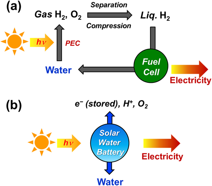
Comparison of electricity generation in (a) conventional system combining photoelectrochemical cell and fuel cell and in (b) solar water battery.
Therefore, as an alternative technology, a solar-powered electrochemical energy storage (SPEES) system, which integrates a photoelectrochemical cell and an electrochemical cell into a single device, has been investigated as a means of simultaneously converting and storing solar energy10. Although the SPEES concept was initially proposed in 1976 by Hodes et al. who combined a chalcogenide PEC with redox-based catholytes (electrolyte in the cathode part), to date this concept has not been studied extensively11. Most SPEES systems are based on the redox reactions between catholytes (e.g., sulfur, iodide, vanadium) and the anode. Upon being irradiated, photo-generated electron-hole pairs in a photoelectrode (PE) are separated by transferring electrons to the anode through an external circuit, and the holes are injected into the catholyte. Therefore, the theoretical cell voltage is determined by the redox potential difference between the anode and catholyte. For example, Licht reported on a SPEES system configured using n-type Cd (Se0.65Te0.35), CoS, and Sn/SnS as the photoelectrode (PE), counter electrode (CE), and anode, respectively12,13. In his design, a polysulfide-based aqueous electrolyte was used as the catholyte (E0 (S/S2−) = −0.48 V vs. NHE), with a redox potential difference with the redox-active anode (SnS) (E0 (Sn2+/Sn) = −0.95 V vs. NHE) of around 0.5 V. As a result, this system produced a cell voltage of around 0.47 V, in the dark, after being photocharged. However, the high fabrication cost and toxicity of the Cd-based photoelectrode and the negative redox potential of the polysulfide-based electrolyte limit further development of this system10. A tri-iodide/iodide (I3−/I−) electrolyte [E0 (I3−/I−) = 0.5 V in water, 0.35 V in organic solvent (vs. NHE)] was also commonly employed as a catholyte in SPEES systems14,15,16. In such systems, dye-sensitized TiO2-PE and a platinum-CE and a WO3 (or polypyrrole) anode were used. WO3 and polypyrrole electrodes store photogenerated electrons by Li+ intercalation or ClO4− doping, respectively, while I− is oxidized to I3− by the photogenerated holes during photocharging. When discharged, I3− was reduced again to I− by accepting electrons from the WO3 or polypyrrole electrodes. SPEES system replacing the solid anode with a redox-active anolyte (electrolyte in the anode part) species such as [Fe(C10H15)2]+/[Fe(C10H15)2], Li2WO4/Li2+xWO4 and quinoxaline (C8H6N2/C8H6N2−), coupled with the use of a tri-iodide/iodide catholyte was also investigated17,18,19. However, an iodine catholyte has drawbacks such as its relatively low energy storage specific capacity, negative redox potential, visible light absorption, and its overly corrosive nature for practical applications10.
Therefore, in this study, we set out to develop an environmental friendly “solar water battery” based on a water oxidation reaction instead of the redox chemistry of a catholyte. Such a solar water battery incorporates the advantages of both the solar water splitting techniques and previously developed SPEES systems: environmental friendliness and the simultaneous conversion and storage of solar energy. In a solar water battery, the catholyte is replaced with water which is oxidized by the photoelectrode during photocharging, and oxygen is reduced to water during discharge. Therefore, the solar water battery does not use or produce any harmful materials. And a high discharge voltage can be produced, because the reduction potential of oxygen is more positive [E0 (O2/H2O) = 1.23 V vs. NHE] than common catholytes (e.g., iodide, sulfur). Furthermore, the solar water battery can both convert solar energy to electricity and simultaneously store it in a single device in the same way as in previous SPEES systems (Fig. 1b). We designed a new configuration for a solar battery to operate it successfully with a high coulombic efficiency. Also, we investigated the important factors affecting the efficiency of the solar water battery and discuss how it operates.
Results
Configuration and mechanism of solar water battery
The cell configuration of the solar water battery is shown in Fig. 2a. The solar water battery has three electrodes: a photoelectrode (PE), electron storage electrode (SE), and counter electrode (CE). For the PE, n-type semiconductor TiO2 was used as this offers a strong oxidizing power and superior stability. For the SE, WO3 with an intercalation potential of around 0–0.4 V (vs. NHE), which is comparable to the proton reduction potential, was used. For the CE, Pt nanoparticles coated FTO electrode was used to increase the oxygen reduction reaction by providing a greater contact area (see Methods).
Figure 2.
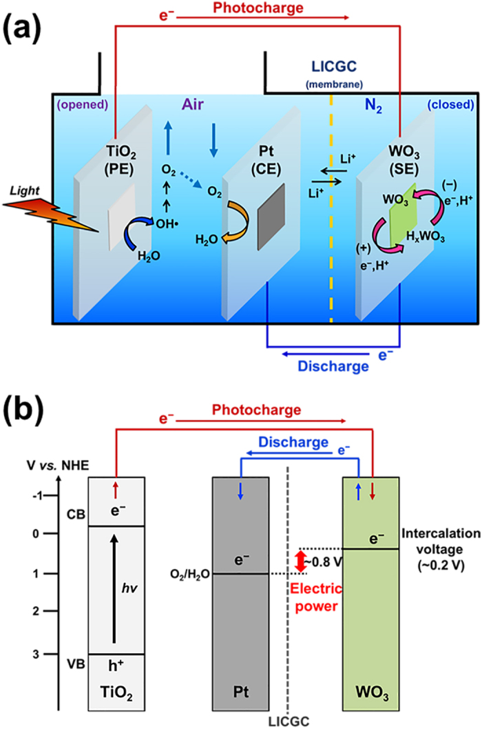
(a) Photocharging and discharging mechanism in solar water battery, (b) energy diagram for each electrode (TiO2 photoelectrode (PE), Pt counter electrode (CE), WO3 storage electrode (SE)).
The morphology and crystallinity of each electrode materials were characterized and confirmed by FE-SEM imaging and XRD measurements (Supplementary Fig. 1). The atmospheres in the solar water battery were divided to improve the efficiency of the photocharge/discharge. The SE is kept in an anoxic state to prevent the self-discharge which is induced by the oxygen reduction reaction. Meanwhile, the part containing PE and CE is opened to air to offer the oxygen efficiently for the reduction on CE and to prevent a volume expansion of cell by the produced oxygen from water oxidation on PE. The detailed reasons and the experiment results for using the different atmosphere will be discussed later. To establish the different atmospheres in each part, a lithium ion conduction glass ceramic (LICGC) membrane, which allows only the transport of lithium ions, but not other ions or oxygen, is applied.
The proposed working mechanism of the solar water battery is shown in Fig. 2b. When illuminated by sunlight, the TiO2-PE is excited and generates an electron-hole pair. The photogenerated electrons in the TiO2-PE are transferred to the WO3-SE through an external circuit under the influence of a thermodynamic energy level difference between the TiO2 and WO3. The transferred electrons are stored in the WO3-SE by redox reactions between W6+ and W5+, accompanied by H+ ion insertion (WO3 + xe− + xH+ ↔ HxWO3). During the discharge process, WO3-SE and Pt-CE are connected and the electrons stored in the WO3-SE move back to the Pt-CE, thus producing electric power. Theoretically, our solar water battery could produce an output voltage of around 0.8 V, which is the difference between the oxygen reduction potential (1.03 V vs. NHE (at pH 3)) at the Pt-CE and the H+ ions-intercalation potential of the WO3-SE (~0.2 V vs. NHE (at pH 3)) (Fig. 2b). We investigated, separately, the photocharge, storage and discharge processes occurring in the solar water battery, and discussed how the solar water battery operates in each process, thus providing evidence for each of those processes.
Solar-energy conversion in TiO2 electrode
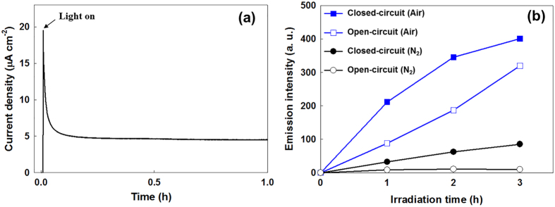
We first checked the feasibility of using WO3-SE as an electrochemical storage electrode in a 2-electrode system (Pt counter electrode) by performing galvanostatic charge/discharge in the dark with a current density of 2 mA g−1 and a cutoff voltage of −1.1 V (Supplementary Fig. 2). The cell stabilized after 10 cycles and exhibited a coulombic efficiency in excess of 90% over 50 cycles, thus confirming the electron storage ability of the WO3 and the well-established cell conditions. Prior to the solar-energy storage test, the TiO2-PE was pre-illuminated with sunlight for 16 h under an open-circuit condition to ensure the a removal of all contamination with organic impurities on the TiO2 surface20. After the cleaning, the TiO2-PE was connected to the WO3-SE through an external circuit and irradiated with sunlight to instigate the photocharging. Figure 3a shows the electron flow from the TiO2-PE to the WO3-SE, which was monitored without applying any external bias. When the TiO2-PE is illuminated, a continuous and stable photocurrent is generated. This is clear evidence for the photo-generated electrons’ transfer from the TiO2-PE to the WO3-SE.
Figure 3.
Time profile of (a) photocurrent and (b) coumarin-OH adduct (7-hydroxycoumarin) generation on photoelectrode when irradiated with sunlight (coumarin 1 mM; pH 3.0).
The force driving the electron transfer from the photoexcited-TiO2 to the WO3 is the difference between the Fermi level of the photoexcited-TiO2 and that of WO3 (ΔV (VF, TiO2 − VF, WO3)). This continues until the energy levels of both electrodes are the same. We estimated the flat band potential of the WO3-SE before and after the photocharge according to the Mott-Schottky plot (Supplementary Fig. 3). The flat band potential of WO3-SE was around 0.1 V (vs. NHE) before the photocharge, becoming –0.3 V (vs. NHE) after being photocharged for 16 h. The shift of the flat-band potential to the negative direction supports our claims that the electrons are transferred to WO3-SE and accumulated. It is important to note that the flat band potential obtained by the Mott-Schottky plots may have to be treated with caution due to the polycrystalline nature of the film, therefore, the estimated values might be different with the real values. But, the shift of the flat band potential is reliable to support the electron storage in WO3-SE. To confirm whether the electron transfer is a result of the photoelectrochemical oxidation of the water on the TiO2-PE, the possible products (OH•, H2O2, O2) of water oxidation were measured. (Equation 1, 2, 3).
 |
 |
 |
Firstly, the OH radicals which appear as intermediaries during the water oxidation were measured using coumarin reagent. The coumarin traps the OH radical in the electrolyte, thus forming fluorescent 7-hydroxycoumarin21. Therefore, the amount of OH radicals could be quantified by measuring the fluorescence emission intensity of the 7-hydroxycoumarin. Figure 3b shows the time profiles of the 7-hydroxycoumarin generation under different experimental conditions during photoelectrochemical water oxidation by the TiO2-PE. When the TiO2-PE is connected to the WO3-SE (closed circuit), the fluorescence emission intensity of the 7-hydroxycoumarin was proportional to the duration of the irradiation, indicating OH radical generation by photoelectrochemical water oxidation. However, the OH radicals were also produced on the TiO2-PE without any connection to the WO3-SE (open circuit) in a system, which can be attributed to the photocatalytic oxidation of the water on the TiO2-PE. Because the photogenerated electrons on the TiO2-PE are consumed by the dissolved oxygen, the photogenerated holes can be used for the water oxidation. However, the quantity of OH radicals produced with the open circuit was less than that produced with the closed circuit. This implies that the WO3-SE connection (closed circuit) encourages the separation of the e−/h+ pair during the photocharging process by providing a greater driving force for the transfer of the photogenerated electrons to the WO3-SE, leading to the increased oxidation of the water. To clarify this, the same experiments were carried out under anoxic (N2) conditions. Under anoxic conditions, almost no OH radical generation was observed with the open circuit due to the fast e−/h+ pair recombination in the absence of oxygen. However, when the WO3-SE acts as an electron acceptor and is connected (closed circuit), a significant quantity of OH radicals was clearly generated. These results confirm that the WO3-SE can provide the driving force needed to transfer the photogenerated electrons, and that photoelectrochemical water oxidation occurs on the TiO2-PE without an external bias. Our results prove that the water acts as the electron source to scavenge the hole in the TiO2-PE. The generation of H2O2 which can be produced by two-electron transfer reaction of water was also measured indicating the water oxidation during the photocharging is evident (Supplementary Fig. 4). The concentration of H2O2 increased linearly during 24 h of photocharging. Since the H2O2 is easily decomposed in the presence of Pt catalyst, the measurement of H2O2 was carried out in the absence of Pt-CE. Besides, the decomposition of H2O2 (2H2O2 → 2H2O + O2) in the presence of Pt-CE after the photocharging was also observed in our experiment results as shown in Fig. S4. After measurement of H2O2 during the photocharging in the absence of Pt electrode for 24 h, the resultant electrolyte was transferred into two vials. Pt electrode was immersed into the electrolyte in one vial, and another vial was kept without Pt electrode. The concentrations of H2O2 in the both electrolytes were compared after 6 h. The sample without Pt electrode showed a small change of the H2O2 concentration, on the other hand, that with Pt electrode showed 100% decomposition of H2O2. These results show us that O2 can be produced through the H2O2 decomposition during the photocharging and subsequently it can be used for the reduction of oxygen during the discharging on Pt-CE. O2 also can be generated by the four-electron transfer from water. However, when we detected O2 evolution in anoxic condition, the produced amount of O2 after 24 h of photocharging was very small or almost negligible. It is attributed to the low efficiency of O2 production by both pathways (H2O2 decomposition, water oxidation) due to a low solar energy conversion efficiency of TiO2 under 1 sun condition, and a low catalytic activity for water oxidation of TiO2-PE without oxygen evolution catalysts.
Storage of photo-generated electrons in WO3 electrode
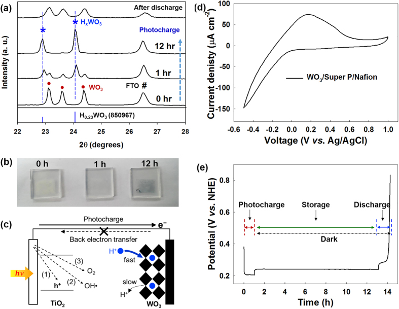
When the photogenerated electrons are transferred to the WO3-SE, tungsten bronze (HxWO3) is formed by H+ ion insertion (WO3 + xe− + xH+ ↔ HxWO3). The formation of HxWO3 is confirmed by X-ray diffraction (XRD) measurement, as shown in Fig. 4a. Compared to the XRD pattern of the WO3 before being irradiated with sunlight, new peaks appear after 1 h of photocharging. The intensities of the new peaks become more obvious after the photocharging continues for another 12 h, while the original peaks of the WO3 almost disappear. The new peaks can be indexed as peaks generated by HxWO3 (refer to JCPDS card: no. 85-0967), indicating the conversion of the WO3 to HxWO3 by the transfer of electrons from the TiO2-PE during photocharging22. The conversion of the WO3 to HxWO3 can also be confirmed by observing the color change during photocharging, as shown in Fig. 4b. For this experiment, a WO3 electrode was prepared without any conductive carbon. (The carbon would interfere with the observation of the color.) The color of the WO3 electrode was found to change from pale yellow to blue, which is the color of HxWO3, as the photocharge progressed, again pointing to the storage of electrons in the WO3, thus forming HxWO3.
Figure 4.
(a) Phase change in XRD patterns of WO3 electrode and (b) Color change in WO3 electrode before and after photocharging (0–12 h). (c) Possible pathways for back electron transfer during photocharging. (d) CV curves of WO3 electrode at a scan rate of 10 mV s−1. (e) Monitoring of electrical potential of WO3 electrode during photocharging, storage, and discharge.
Figure 4c illustrates various possible back electron transfer pathways for the electrons stored in the WO3-SE to the TiO2-PE during the photocharge. The stored electrons in the WO3-SE can go back to (1) recombine with the hole in the TiO2-PE or (2) react with OH radical or (3) react with the oxygen supplied from the air. However, the stable intercalated form of the HxWO3 suppresses the back electron transfer during the photocharge. To verify this, we have measured cyclic voltammetry (CV) of WO3-SE. As shown in Fig. 4d, a sharp peak in the current appeared during cathodic polarization, while a moderate and broad curve was observed during anodic polarization. The CV results indicate that the WO3 has fast intercalation but slow deintercalation characteristics, and that it suppresses the back electron transfer from the HxWO3 to the TiO2 during the photocharging process. This proves that the WO3 has excellent storage properties as the SE of the solar water battery, which is needed to overcome the attraction of the strong oxidants, namely, the holes in PE, the OH radicals, and the oxygen. The stable electron storage in the WO3 was also identified by the monitoring of the electrical potential of the WO3-SE during photocharge/storage/discharge, as shown in Fig. 4e. When the TiO2-PE was irradiated with sunlight for the photocharging, the electrical potential of the WO3-SE (a mixed potential of TiO2-PE and the WO3-SE owing to an ohmic contact of both electrodes) was decreased sharply and saturated at around 0.2 V (vs. NHE). When the light irradiation was closed and both electrodes were disconnected to halt the photocharging, the electrical potential of the WO3-SE (a single potential of the WO3-SE) increased slightly to 0.23 V (vs. NHE). This correspond to the intercalation potential of the H+ into the WO323,24. The electrical potential of the WO3-SE in an open-circuit condition was well maintained for 10 h, thus exhibiting stable electron storage without self-discharge. In addition to strong storage properties of WO3-SE, the anoxic state of the WO3-SE part in the solar water battery contributes to the stable storage without self-discharge by preventing the reaction of the electrons with the dissolved oxygen in the electrolyte during the storage period.
Discharge generating electric power
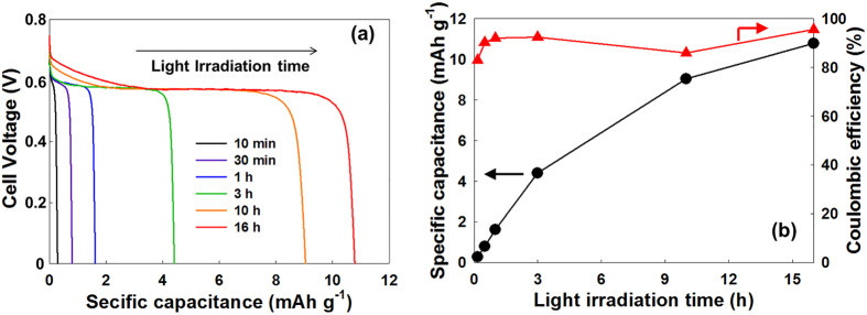
To generate electrical power, the photocharged WO3-SE were connected to the Pt-CE to discharge, and were galvanostatically discharged with a current density of 1 mA g−1 until the cell voltage reached 0 V. According to the voltage profile observed during the discharge in Fig. 5a, this solar water battery produced an stable output voltage of around 0.6 V with a wide voltage plateau, regardless of the duration of the light irradiation. The voltage plateau region is attributed to the H+ ion deintercalation process as a faradaic process. This discharge voltage profile proves that this solar water battery can convert solar energy to electricity with a stable output voltage. However, the observed average output voltage (around 0.6 V) is lower than the theoretical output voltage (around 0.8 V), which could be attributed to the overpotential of the deintercalation reaction at the WO3-SE and the low ion conductivity of the LICGC membrane. Figure 5b shows the dependence of the discharge capacitance on the duration of the light irradiation. The specific discharge capacitance increased almost proportionally to the duration of the light irradiation, and it confirms again the solar-energy storage in this solar water battery system. Coulombic efficiency of the solar water battery excessed 90% regardless of the duration of the photocharging, and the specific discharge capacitance reached around 10 mAh g−1 after 16 h of irradiation. The coulombic efficiency was calculated from the ratio of the total charge of the photocurrent to that of the discharge current. This high coulombic efficiency of the solar water battery points to all the stored electrons in the WO3-SE being effectively used to generate electricity. And the reconversion of HxWO3 to WO3 after the discharging was confirmed by XRD as shown in Fig. 4a.
Figure 5.
(a) Galvanostatic discharge voltage profile and (b) specific discharge capacitance and coulombic efficiency after photocharging for 10 min–16 h. Discharge current density was 1 mA g−1.
Discussion
Compared with previous SPEES systems, the solar water battery required a newly designed cell configuration based on the presence of oxygen in the electrolyte. Firstly, the air-atmosphere (opened) condition of the chamber where the TiO2-PE and Pt-CE are immersed in is beneficial not only for preventing the expansion of the cell by the generated oxygen during the photocharge, but also for the efficient extraction of electrons from the photocharged WO3-SE to Pt-CE. When the Pt-CE chamber is purged with N2, to probe the role of the air-atmosphere condition, the coulombic efficiency of the discharge after 1 h of photocharging was drastically reduced to 23% of the value measured in an air-atmosphere condition (92%) (Supplementary Fig. 5). The oxygen produced as a result of the water oxidation during the photocharging could subsequently be used for the reduction on the Pt-CE during the discharge step with regenerating the water in the same chamber (Equation 4).
 |
However, the amount of oxygen produced by the TiO2-PE is too small to extract the stored electrons in WO3 efficiently during the discharging resulting in a low coulombic efficiency. Even if the photoanode can achieve the efficient oxygen evolution by adapting cocatalysts or by using efficient materials for the solar energy conversion, a cell volume expansion by oxygen evolution will be a potential problem for the battery safety. Therefore, we suggested an air-opened cell for the TiO2-PE, Pt-CE part for the efficient electrons extraction during the discharging and the safety issue.
Secondly, WO3-SE kept in anoxic condition is essential for stable storage of stored electrons. When we maintained the solar water battery in the open-circuit state for 10 h after 1 h of photocharging, the specific discharge capacitance was found to be 99% of that measured immediately after photocharging (without any storage time). When the entire cell was in the oxic state, a self-discharge occurred and the storage capacity of the cell was severely compromised. On the other hand, when the entire cell was in the anoxic state, photocharging was favored but the discharge efficiency was drastically decreased as we showed previously. The high coulombic efficiency of the solar water battery is clearly related to the configuration of the cell with separate oxic and anoxic chambers. Furthermore, when we tested the cyclability of the solar water battery, we found that the capacity retention rate was 85% after 10 photocharge/discharge cycles while maintaining a high coulombic efficiency (Fig. 6). These results prove that the solar water battery offers a repeatable and promising means of solar energy conversion and storage.
Figure 6. Photocharge/discharge cycle performance plot of solar water battery.
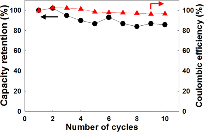
(Photocharging time: 1 h, discharge current density: 1 mA g−1).
A solar water battery has a merit of relatively high output voltage. For example, there have been some SPEES systems that utilized a dye-sensitized TiO2 electrode and WO3 electrode as the PE and SE, respectively. These produced a small average output voltage (around 0.4 V) resulted from the difference in the WO3 energy levels and the redox potential of I3−/I− (0.536 V vs. NHE) on the counter electrode (Pt)25. Meanwhile, because the output voltage of this solar water battery is based on the difference in the WO3 intercalation energy level (average 0.2 V vs. NHE) and the oxygen reduction reaction [O2/H2O (1.03 V vs. NHE at pH 3], it can have a cell voltage (~0.8 V) that is around 0.4 V larger than the cases described above. Although the maximum discharge voltage of around 0.8 V was not achieved at this point, due to the large overpotential, the development of the counter electrode with a lower overpotential or a thinner LICGC membrane with a higher ionic conductivity could increase the output voltage. The capacity of the solar water battery could also be improved by using more efficient PE, SE, and CE materials which offers better efficiencies. For PE, the water oxidation could be enhanced by using photoactive materials which have a high visible light absorption and a high conduction band edge potential to increase a potential difference (internal bias) with WO3, or by adapting an efficient water oxidation cocatalyst to decrease an overpotential for the water oxidation. And for the efficient electron storage, SE could be modified to have a high surface area or good conductivity. The improvement of the efficiency of the oxygen reduction on CE is also could be achieved by the modification of CE property. Recent well-developed and advanced materials for solar water splitting and electrochemical cell (e.g. fuel cell) offer considerable potentials for the development of a solar water battery.
Additionally, a solar water battery has another unique and promising advantage. That is, pollutants can be used to take the place of the water, and be used as an electron source for scavenging photo-generated holes in the PE during photocharging. The system in which the PE chamber is open to the air is better suited to such oxidative degradation of pollutants. We have conducted preliminary tests on the degradation of 4-chlorophenol (a non-biodegradable pollutant), and found that the photocurrent generation was sharply increased and maintained without any drastic decay when 4-chlorophenol was injected into the electrolyte (Supplementary Fig. 6). This indicates that 4-chlorophenol could act as a more efficient oxidant than water, given that simultaneous pollutant degradation and electron storage are feasible in this system. The degradation of organic pollutants is also possible through reductive reaction pathways (i.e. generation of reactive oxygen species (ROS) such as superoxide radical) on the CE during discharge, extending the applications for the treatment of organic pollutants in the night by using the stored electrons during the daytime. More detailed research addressing the development of such a pollutant-degrading solar water battery is currently under investigation.
In conclusion, we have reported on a suitable cell design and configuration for a solar water battery based on water oxidation with a high coulombic efficiency. The solar water battery is environmentally friendly and can provide an alternative to conventional photoelectrochemical water splitting. It could simultaneously convert and store solar energy in a compact system as an alternative to the hydrogen gas generation from photoelectrochemical water splitting, thus simplifying the conventional process from hydrogen production to electricity generation. The cell configuration and operating conditions, such as the atmosphere in each chamber, were critical to the operation of the solar water battery with a good coulombic efficiency. Although the specific discharge capacitance of the cell was not so high (around 10 mAh g−1 after 16 h of photocharging) at this point, there is considerable scope for improvement by adapting the numerous materials and technologies developed for solar water splitting which have proven to be an efficient means of solar energy conversion.
Methods
Fabrication of solar water battery
The solar water battery consists of a TiO2 (P25, Degussa) photoelectrode (PE), a WO3 (Aldrich) storage electrode (SE), a platinum (Aldrich) counter electrode (CE), and a lithium-ion-conducting glass ceramic (LICGC, 0.18-mm, Li1+x+yAlxTi2−xSiyP3−yO12 (OHARA Inc., Japan)) membrane. To fabricate the WO3-SE, WO3 was mixed with Super P and Nafion (Aldrich) (8:1:1 by weight) in ethanol. The slurry was coated onto an FTO by using a doctor-blade method and then dried at 110 °C in a vacuum oven for 12 h. The TiO2-PE and Pt-CE were fabricated using a doctor blade method without any conductive agent or binder as these can possibly affect the light absorption or the surface reaction with the water. TiO2-PE and Pt-CE electrodes were prepared according to the literature method26. Briefly, TiO2 or Pt powder was mixed with polyethylene glycol (PEG). The slurry was cast onto an FTO plate using a doctor-blade technique and then the TiO2/FTO electrode or Pt/FTO electrode was heated at 450 °C for 30 min to drive off the binder. When a WO3 electrode without any conductive agent or binder was needed, it was prepared using the same method as that for the TiO2 electrode or Pt electrode, with the exception of the loading material. The electrolyte used for the solar water battery was 10 mM Li2SO4 with a pH of 3. The pH of the solution was adjusted to 3.0 by adding either H2SO4 or NaOH. The deionized water was ultrapure (18 MΩ•cm), prepared using a RephiLe Bioscience purification system.
Material characterization and analysis
The morphologies of TiO2, WO3, and Pt were characterized by using field emission scanning electron microscopy (FE-SEM, Hitachi, S-4800). X-ray diffraction (XRD) measurement was carried out using Cu Kα radiation (Empyrean X-ray diffractometer). The generation of OH radicals was measured by using a fluorescence method with coumarin as a chemical trap for the OH radicals (Equation 5). The fluorescence emission intensity of the 7-hydroxycoumarin was measured using a spectrofluorometer (Perkin Elmer LS-55) at 460 nm while being excited at 332 nm.
 |
The concentration of H2O2 at various time intervals was determined by the DPD colorimetric method, which is based on the horseradish peroxidase (Aldrich)-catalyzed reaction of H2O2 with N,N-diethyl-p-phenylenediamine (DPD, 97%, Aldrich), using a UV-visible spectrophotometer (Simadzu, λmax = 551 nm, ε = 21000 M−1 cm−1)27.
(Photo)electrochemical tests
The (photo)electrochemical measurements were carried out using a potentiostat (ZIVE MP1, WONATECH). The WO3-SE part of the solar water battery was purged with nitrogen gas prior to the measurement. For the photocharging test, a solar simulator (1 sun, AM 1.5 G, Oriel) was used as the light source. The photocurrent was measured by using the TiO2 electrode as a working electrode (WE) and the WO3 electrode as both a counter electrode (CE) and reference electrode (RE) with no bias applied. During the discharge, the solar water battery was discharged to 0 V (vs. the Pt electrode) using the WO3 electrode as the WE and the Pt electrode as the CE and RE at a current density of 1 mA g−1. Cyclic voltammetry (CV) measurement was performed by using a conventional three-electrode system in a beaker cell containing the same electrolyte solution under an air atmosphere. CV was carried out over a potential range of −0.5–1 V (vs. Ag/AgCl) at a scan rate of 10 mV s−1. When the photocharging test using a pollutant as the electron source was conducted, 4-Chlorophenol (4-CP, Aldrich) was instantly injected into the cathode part of the solar water battery during the photocharging such that the final concentration of the 4-CP was 100 μM.
Additional Information
How to cite this article: Kim, G. et al. Solar-rechargeable battery based on photoelectrochemical water oxidation: Solar water battery. Sci. Rep. 6, 33400; doi: 10.1038/srep33400 (2016).
Supplementary Material
Acknowledgments
This study was supported by the DGIST R&D Program of the Ministry of Science, ICT and Technology of Korea (16-EN-01).
Footnotes
Author Contributions G.K. and Y.P. designed and performed the experiments, and wrote the manuscript. M.O. fabricated electrodes and characterized.
References
- Seo J. et al. Mg-Zr cosubstituted Ta3N5 photoanode for lower-onset-potential solar-driven photoelectrochemical water splitting. J. Am. Chem. Soc. 137, 12780–12783 (2015). [DOI] [PubMed] [Google Scholar]
- Zhang Z. et al. Toward efficient photoelectrochemical water-splitting by using screw-like SnO2 nanostructures as photoanode after being decorated with CdS quantum dots. Nano Energy 19, 318–327 (2016). [Google Scholar]
- Sheng W. et al. Quantum dot-sensitized hierarchical micro/nanowire architecture for photoelectrochemical water splitting. ACS Nano 8, 7163–7169 (2014). [DOI] [PubMed] [Google Scholar]
- Srivastava S. et al. Size-selected TiO2 nanocluster catalysts for efficient photoelectrochemical water splitting. ACS Nano 8, 11891–11898 (2014). [DOI] [PubMed] [Google Scholar]
- Fujishima A. & Honda K. Electrochemical photolysis of water at a semiconductor electrode. Nature 238, 37–38 (1972). [DOI] [PubMed] [Google Scholar]
- Yang X. et al. Nitrogen-doped ZnO nanowire arrays for photoelectrochemical water splitting. Nano Lett. 9, 2331–2336 (2009). [DOI] [PubMed] [Google Scholar]
- Torella J. P. et al. Efficient solar-to-fuels production from a hybrid microbial-water-splitting catalyst system. Proc. Natl. Acad. Sci. 112, 2337–2342 (2015). [DOI] [PMC free article] [PubMed] [Google Scholar]
- Cipriani G. et al. Perspective on hydrogen energy carrier and its automotive applications. Int. J. Hydrogen Energy 39, 8482–8494 (2014). [Google Scholar]
- Zhou L. Progress and problems in hydrogen storage methods. Renew. Sust. Energ. Rev. 9, 395–408 (2005). [Google Scholar]
- Yu M. et al. Solar-powered electrochemical energy storage: An alternative to solar fuels. J. Mater. Chem. A 4, 2766–2782 (2016). [Google Scholar]
- Hodes G., Manassen J. & Cahen D. Photoelectrochemical energy conversion and storage using polycrystalline chalcogenide electrodes. Nature 261, 403–404 (1976). [Google Scholar]
- Licht S., Hodes G., Tenne R. & Manassen J. A light-variation insensitive high efficiency solar cell. Nature 326, 863–864 (1987). [Google Scholar]
- Licht S. & Manassen J. Thin film cadmium chalcogenide/aqueous polysulfide photoelectrochemical solar cells with in-situ tin storage. J. Electrochem. Soc. 134, 1064–1070 (1987). [Google Scholar]
- Hauch A., Georg A., Opara Krašovec U. & Orel B. Photovoltaically self-charging battery. J. Electrochem. Soc. 149, A1208–A1211 (2002). [Google Scholar]
- Saito Y. et al. Energy-storable dye-sensitized solar cells with interdigitated nafion/polypyrrole-Pt comb-like electrodes. Chem. Lett. 39, 488–489 (2010). [Google Scholar]
- Nagai H. & Segawa H. Energy-storable dye-sensitized solar cell with a polypyrrole electrode. Chem. Commun. 10, 974–975 (2004). [DOI] [PubMed] [Google Scholar]
- Liu P. et al. A solar rechargeable flow battery based on photoregeneration of two soluble redox couples. ChemSusChem 6, 802–806 (2013). [DOI] [PubMed] [Google Scholar]
- Yan N. F., Li G. R. & Gao X. P. Solar rechargeable redox flow battery based on Li2WO4/LiI couples in dual-phase electrolytes. J. Mater. Chem. A 1, 7012–7015 (2013). [Google Scholar]
- Yan N. F., Li G. R. & Gao X. P. Electroactive organic compounds as anode-active materials for solar rechargeable redox flow battery in dual-phase electrolytes. J. Electrochem. Soc. 161, A736–A741 (2014). [Google Scholar]
- Kim W., Seok T. & Choi W. Nafion layer-enhanced photosynthetic conversion of CO2 into hydrocarbons on TiO2 nanoparticles. Energy Environ. Sci. 5, 6066–6070 (2012). [Google Scholar]
- Kim J., Lee C. W. & Choi W. Platinized WO3 as an environmental photocatalyst that generates OH radicals under visible light. Environ. Sci. Technol. 44, 6849–6854 (2010). [DOI] [PubMed] [Google Scholar]
- Higashimoto S. et al. Photocharge-discharge behaviors of hybrid WO3/TiO2 film electrodes. J. Electrochem. Soc. 154, F48–F54 (2007). [Google Scholar]
- Mi Q. et al. Photoelectrochemical oxidation of anions by WO3 in aqueous and nonaqueous electrolytes. Energy Environ. Sci. 6, 2646–2653 (2013). [Google Scholar]
- Lee S. H. et al. Crystalline WO3 nanoparticles for highly improved electrochromic applications. Adv. Mater. 18, 763–766 (2006). [Google Scholar]
- Saito Y., Uchida S., Kubo T. & Segawa H. Surface-oxidized tungsten for energy-storable dye-sensitized solar cells. Thin Solid Films 518, 3033–3036 (2010). [Google Scholar]
- Kim G. & Choi W. Charge-transfer surface complex of EDTA-TiO2 and its effect on photocatalysis under visible light. Appl. Catal. B. 100, 77–83 (2010). [Google Scholar]
- Kim H.-i. et al. Harnessing low energy photon (635 nm) for the production of H2O2 using upconversion nanohybrid photocatalysts, Energy Environ. Sci. 9, 1063–1073 (2016). [Google Scholar]
Associated Data
This section collects any data citations, data availability statements, or supplementary materials included in this article.


