Abstract
Over the past decade, a major effort was made to miniaturize engineered tissues, as to further improve the throughput of such approach. Most existing methods for generating microtissues thus rely on T-shaped cantilevers made by soft lithography and based on the use of negative SU-8 photoresist. However, photopatterning T-shaped microstructures with these negative photoresists is fastidious and time-consuming. Here we introduce a novel method to quickly generate T-shaped cantilevers dedicated to generation of cellular microtissues, based on the use of positive photoresist. With only two layers of photoresist and one photomask, we were able to fabricate arrays of microwells in less than 3 h, each containing two T-shaped cantilevers presenting either a rectangular or a circular geometry. As a proof of concept, these arrays were then replicated in poly(dimethylsiloxane) and microtissues composed of NIH 3T3 fibroblasts encapsulated in collagen I were generated, while the two cantilevers simultaneously constrain and report forces generated by the microtissues. Immunostainings showed longitudinally aligned and elongated fibroblasts over the whole microtissue after 8 days of culture. The method described here opens the potential to quick prototyping platforms for high-throughput, low-volume screening applications.
Keywords: Photolithography, positive photoresist, PDMS, microtissues
Introduction
Over the past decade, three dimensional (3D) encapsulations of cells in natural or synthetic hydrogels have known a growing interest as model systems for many morphogenetic processes (Ader and Tanaka 2014; Baker and Chen 2012). Such systems indeed present mechanical and structural properties closer to the native tissues than 2D culture. However, the scale of these engineered tissues often is incompatible with live cell microscopy and requires large quantities of cells, which can be a key limitation for rare cells such as primary cells or induced pluripotent stem cells. Recently, Legant et al. developed a microfabricated platform to engineer 3D microtissues with an easy access to cell-generated forces (Legant et al. 2009) thanks to biological microelectromechanical systems (Bio-MEMS) T-shaped cantilevers. This approach has since been widely used for engineering microtissue models of myocardial (Boudou et al. 2012; Hinson et al. 2015), skeletal (Kalman et al. 2015; Sakar et al. 2012) or airway smooth muscle tissues (West et al. 2013), as well as for studying mechanotransduction events in 3D tissues (Sakar et al. 2016; Zhao et al. 2013). However, and although different methods have already been described, the microfabrication of such platforms is still a long, complicated and expensive process. Indeed, it is still challenging to microfabricate T-shaped cantilevers by photolithography with negative photoresist as the exposure of the cap layer can induce an unwanted cross-linking of the underlying post layers. The current approaches require two photomasks and four layers of 2 to 5 different photoresists, meaning long and numerous spin-coating, baking and exposure steps (Legant et al. 2009; Liu et al. 2014; Ramade et al. 2014). The whole process takes more than 10h, thus limiting the prototyping speed. Depending on the cell type, the engineering of microtissues can be limited by long term, morphological instabilities induced by the mechanical stresses arising from the constraint distribution (Wang et al. 2013), and the geometry of the T-shaped cantilevers thus need to be adapted to the cell type to limit these instabilities..
Therefore, quick and simple methods to microfabricate T-shaped cantilevers by photolithography are important as to facilitate and widen the use of this microtissue technology. Here we present a new microfabrication approach by photolithography of two successive spin coatings and exposures of thick positive photoresist through only one photomask. We demonstrate the ability for quick and easy prototyping T-shaped cantilevers by microfabricating two arrays of microwells, each one containing either two circular or two rectangular T-shaped cantilevers, in less than 3h. The obtained master templates can then be replicated in poly(dimethylsiloxane) (PDMS) before seeding cells that form microtissues over time. As a proof of concept, we generated microtissues composed of 3T3 fibroblasts embedded in collagen and quantified the tissue-generated tension in function of time and cantilever geometry.
Materials and methods
Microfabrication
Master templates, consisting of 13 x 10 microwells containing two T-shape cantilevers, were created by photopatterning bilayers of AZ40XT positive photoresist (Microchemicals) on 5-inch silicon wafers. Both layers composed the walls of the microwells. The first layer composed the bottom part (post) of the T-shape cantilevers whereas the second layer composed the slightly wider top part (cap) of the cantilevers. Both post and cap parts were created via photopatterning through a 5-inch photomask (Toppan Photomasks) containing both features and designed with the free software KLayout. The first layer was spin-coated for 3 s at 1500 rpm before soft baking 5 min at 65 °C and 15 min at 125 °C. After cooling to room temperature, the first layer was exposed to UV light (330mJ/cm²) through the photomask with a Karl Suss MA 150 mask aligner (Suss Microtec). The second layer of AZ40XT photoresist was then spin-coated for 30 sec at 4000 rpm before soft baking 5 min at 65 °C and 10 min at 110 °C. After cooling to room temperature, the second layer was exposed to UV light (120 mJ/cm²) through the same photomask rotated by 180°C before hard baking 5 min at 65 °C and 10 min at 110 °C. The master templates were finally developed in twelve steps of 60 s each in MF-26A developer (Dow Electronic Materials). Note that all baking temperatures were reached slowly by using a temperature ramp of 5°C/min.
Replication of the master templates
Poly(dimethylsiloxane) (PDMS; Sylgard 184; Dow-Corning) platforms were obtained by double replication of the master templates as previously described [Ramade 2014]. Master templates were first cleaned and activated by plasma treatment for 45 sec at 12 W (Evactron, XEI Scientific Inc.) before vapor deposition of trichloro(1H,1H,2H,2H-perfluorooctyl)silane (Sigma 448931). PDMS prepolymer and curing agent were mixed, stirred thoroughly and degassed before casting on the master template. After a second degassing to insure penetration of the viscous PDMS within the microwells, the mixture was cured for 12 h at 65°C. The PDMS stamps were then carefully peeled off from the master template and similarly replicated a second time to obtain the final platform.
Mechanical testing
30x50x5 mm strips of PDMS were mechanically tested through uniaxial extension to determine tensile properties. Testing was performed with an Instron 5848 Microtester (Instron). Stiffness was determined over a 3% strain range from the linear region of the force–elongation curve. Using the crosssectional area and gauge length, Young’s modulus was calculated from the analogous stress–strain curve.
Cell culture and microtissues seeding
Murine 3T3 fibroblasts (<15 passages, kindly provided by Corinne Albiges-Rizo, IAB, Grenoble) were cultured in a Dulbecco’s Modified Eagle Medium (DMEM, Invitrogen) supplemented with 10% fetal bovine serum (FBS, PAA Laboratories), 100U/mL penicillin G, and 100mg/mL streptomycin (Invitrogen). The cells were subcultured prior to reaching 60–70% confluence.
Microtissue seeding was performed as previously described (Ramade et al. 2014). Briefly, PDMS platforms were first sterilized for 15 minutes under UV light followed by immersion in 70% ethanol for 2 minutes. Pluronic F127 (Sigma) treatment at 0.2% in PBS was then applied for 2 minutes to limit cell adhesion. A reconstitution mixture, consisting of 2 mg/mL liquid neutralized collagen I from rat tail (BD Biosciences), was then added to the surface of the substrate on ice, degassed and centrifuged at 3000 rpm for 90 s to insure collagen penetration into the microwells. A cooled suspension of cells at a density of 200,000 cells per mL of reconstitution mixture was then added to the platform and the entire assembly was centrifuged at 1200 rpm for 90 s to drive the cells into the microwells, resulting in approximately 200 cells per well. Excess collagen and cells were removed by de-wetting the surface of the platform before incubating at 37°C to induce collagen polymerization. The appropriate medium was then added to each platform.
Immunofluorescence and microscopy
After 8 days of culture, microtissues were fixed with 4% paraformaldehyde in PBS and permeabilized with 0.2% Triton X-100 in PBS. Actin was labeled with phalloidin-TRITC (Sigma) and nuclei were stained with DAPI (Life Technologies).
Alive microtissues were imaged with an inverted microscope (Axiovert 200M, Zeiss) using a 10X objective whereas fixed microtissues were imaged with a confocal laser scanning microscope (LSM 700, Zeiss) equipped with a 20x objective.
Results & Discussion
Microfabrication
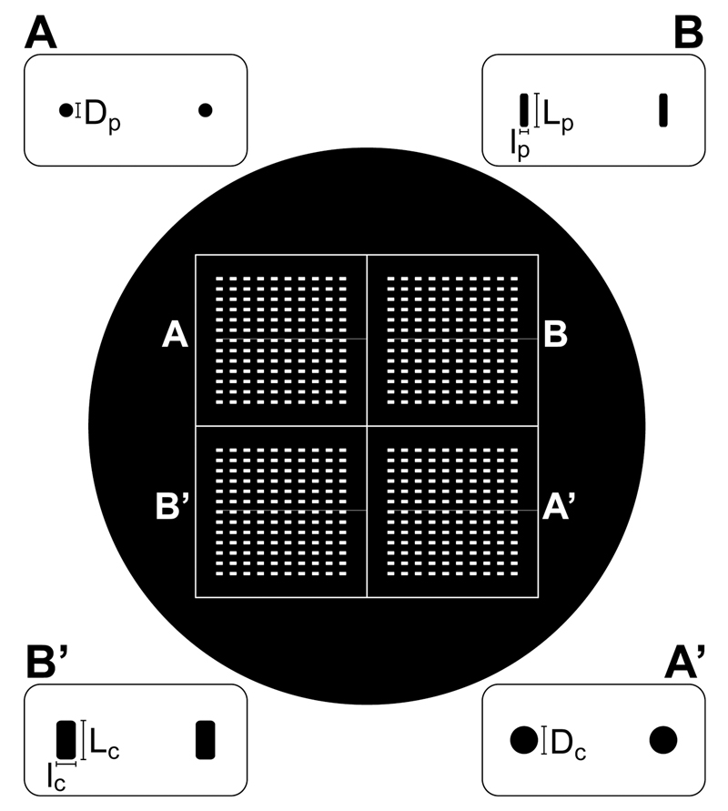
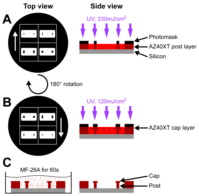
Most existing methods for creating width-changing structures such as T-shaped cantilevers are based on the use of negative SU-8 photoresist. Indeed, SU-8 photoresists are especially relevant for very thick and high aspect ratio microstructures. However, photopatterning T-shaped microstructures with these negative photoresists is very challenging as parts of the unexposed lower SU-8 layer will be exposed if the upper SU-8 layer requires a wider exposure area. The current approaches thus require two photomasks and four layers of two to five different photoresists, meaning long and numerous spin-coating, baking and exposure steps, the whole process lasting over more than 10h (Liu et al. 2014; Ramade et al. 2014). Recently, Greiner et al. reported the possibility of microfabricating 170 µm-tall structures with a single layer of the positive photoresist AZ 40XT (Greiner et al. 2013). We thus built on these results to elaborate a novel approach necessitating only two layers of photoresist. Photomasks being expensive, we also wanted to develop a method requiring only one photomask. We thus designed a photomask presenting both the bottom and cap features that can be aligned by simple 180° rotation (Fig. 1). The post of the cantilever thus consisted of a single, ~100 µm thick layer of AZ 40XT obtained by a short spin coating at 1500 rpm. After a slowly applied soft baking step, the first layer was exposed (Fig. 2.A) before being coated with a second, ~20 µm layer of AZ 40XT. The photomask was then rotated 180° and aligned such as the slightly larger cap features framed the post features (Fig. 2.B). After the second exposure, the AZ40XT bilayer was submitted to a slowly applied post-exposure baking. The AZ 40XT master templates were finally developed to reveal microwells of 800 x 400 x 100 µm containing two T-shaped cantilevers of circular or rectangular geometries (Fig. 2.C). The whole process took about 3 h, at least three times faster than existing methods (Liu et al. 2014; Ramade et al. 2014).
Figure 1. Schematic of the photomask.
Overview and details of the 5-inch photomask presenting both post (A-B) and cap (A’-B’) features that can be aligned by a 180° rotation of the photomask. Dimensions of the features are given in Fig. 3.
Figure 2. Microfabrication of the master template.
(A) The bottom layer of AZ 40XT is first spin coated and exposed, then (B) the top layer of AZ 40XT is spin coated and exposed before (C) development in MF-26A to obtain the master template.
PDMS Replication
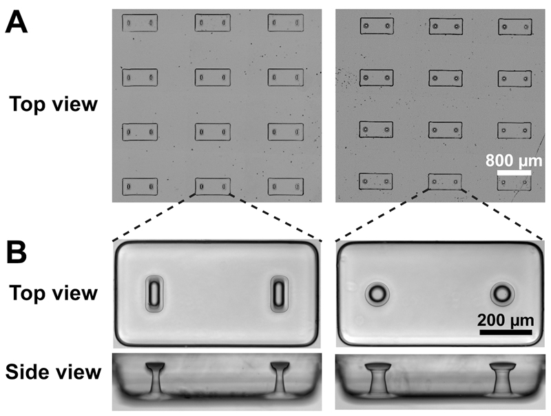
Thanks to the vapor deposition of trichloro(1H,1H,2H,2H-perfluorooctyl)silane on the master template surface prior to replication, we were able to faithfully replicate the microstructures in PDMS (Table 1 and Figure 3). We thus obtained PDMS stamps that were similarly silanized before a second replication to obtain the final PDMS microstructured platform. This double replication technique allowed to (i) avoid demolding difficulties associated with inverted T-shaped cavities such as broken cantilever caps (Liu et al. 2014), and (ii) limit the use and eventual deterioration of the master templates as these flexible PDMS stamps can be replicated many times.
Table 1. Dimensions of the PDMS cantilevers replicated from the master template.
| Dimensions | Rectangular geometry | Circular geometry | ||
|---|---|---|---|---|
| Post (lp x Lp) | Cap (lc x Lc) | Post diameter (Dp) | Cap diameter (Dc) | |
| Photomask feature dimension (µm) | 30 x 120 | 70 x 140 | 60 | 100 |
| Cantilever width (µm) | 29 ± 2 x 101 ± 4 |
69 ± 3 x 137 ± 1 |
56 ± 2 | 101 ± 2 |
| Cantilever height (µm) | 104 ± 12 | 18 ± 9 | 101 ± 7 | 22 ± 3 |
| Estimated k (N/m) | 0.6 ± 0.1 | 1.3 ± 0.1 | ||
Figure 3. Replication in PDMS of rectangular and circular cantilevers.
(A) Large arrays of microwells, each containing two T-shaped cantilevers. (B) Top and side views of a microwell containing rectangular and circular cantilevers.
As shown in Table 1 and Fig. 3, the photomask features were faithfully reproduced. We used linear bending theory to estimate the load-displacement relationship for the two different geometries. The Young’s modulus of the PDMS was measured as 1.6 ± 0.1 MPa, leading to spring constants k of 0.6 N/m and 1.3 N/m for the rectangular and circular cantilevers, respectively. These spring constants were then used to link the measured cantilever deflections d to the amount of force generated by microtissues F: F = k.d.
Microtissue Engineering
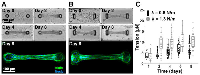
As a proof of concept, we generated microtissues composed of 3T3 fibroblasts embedded in collagen. The PDMS platform was immersed in a suspension of NIH 3T3 fibroblasts and reconstitution mixture (liquid neutralized collagen I), and the entire assembly was centrifuged to drive the cells into the micropatterned wells. Excess collagen and cells were removed and the remaining constructs were polymerized. Over time of cultivation, the cells spread inside the matrix and spontaneously compacted the matrix (Fig. 4). The two cantilevers incorporated within each template anchored the contracting matrix, constraining the contraction of the collagen matrix to form a linear band that spanned across the cap of the pair of cantilevers. This resulted in a large array of microtissues anchored to the tips of the cantilevers per substrate. After cell seeding, at day 0, the collagen matrix contained evenly distributed, amorphous, round fibroblasts (Fig. 4.A-B). Over time, cell compacted and remodeled the matrix by exerting forces that deflected the cantilevers. The spring constants were used to link cantilever deflections to the cell-generated tension (Fig. 4.C). For both cantilever geometry, the cell-generated tension increased up to day 3-4 before stabilizing with plateau values of 6.5 ± 2.4 µN and 10.4 ± 3.7 µN for rectangular (k = 0.6 N/m) and circular (k = 1.3 N/m) cantilevers, respectively. As previously described (Legant et al. 2009), the spring constant of the cantilevers impacted the tension generated by fibroblasts, with higher tensions associated with stiffer cantilevers Immunostaining of microtissues showed longitudinally aligned and elongated fibroblasts over the whole microtissue after 8 days of culture (Fig. 4.A-B).
Figure 4. Temporal evolution of microtissues composed of NIH 3T3 fibroblasts in collagen gels.
Representative images and immunostainings (actin in green, nuclei in blue) depicting the time course of a contracting microtissue tethered to circular (A) and rectangular (B) cantilevers. (C) Temporal evolution of the tension generated by microtissues tethered to rectangular (k = 0.6 N/m, in black) and circular (k = 1.3 N/m, in gray) cantilevers.
Conclusions
In conclusion, our new microfabrication method using positive photoresist allowed for quick, easy and less expensive generation of T-shaped cantilevers. The photoresist master template was faithfully replicated in PDMS to obtain arrays of microwells, each containing two cantilevers. We demonstrated the ability to engineer two different cantilever geometries with one photomask in less than 3 h, thus provide valuable opportunities to quickly screen the effects of the spatial organization of the environment on the architecture of the microtissue. Indeed, both rectangular and circular geometries enabled the formation of fibroblast-based microtissues whose tension was tracked over time by measuring the deflection of the cantilevers. The method described here opens the potential to fast prototyping of microtissue devices for high-throughput, low-volume screening applications.
Acknowledgements
The authors thank the members of the technical staff of the PTA cleanroom in Grenoble for their technical support. This work was partly supported by the French RENATECH network. This work was supported by the European Commission, FP7 via an ERC Starting grant to C.P. (BIOMIM, GA 239370) and a PhD fellowship to BK.
References
- Ader M, Tanaka EM. Curr Opin Cell Biol. 2014;31:23. doi: 10.1016/j.ceb.2014.06.013. [DOI] [PubMed] [Google Scholar]
- Baker BM, Chen CS. J Cell Sci. 2012;125:3015. doi: 10.1242/jcs.079509. [DOI] [PMC free article] [PubMed] [Google Scholar]
- Boudou T, Legant WR, Mu A, Borochin MA, Thavandiran N, Radisic M, Zandstra PW, Epstein JA, Margulies KB, Chen CS. Tissue Eng Part A. 2012;18:910. doi: 10.1089/ten.tea.2011.0341. [DOI] [PMC free article] [PubMed] [Google Scholar]
- Greiner F, Quednau S, Dassinger F, Sarwar R, Schlaak HF, Guttmann M, Meyer P. J Micromechanics Microengineering. 2013;23:025018. [Google Scholar]
- Hinson JT, Chopra A, Nafissi N, Polacheck WJ, Benson CC, Swist S, Gorham J, Yang L, Schafer S, Sheng CC, Haghighi A, et al. Science. 2015;349:982. doi: 10.1126/science.aaa5458. [DOI] [PMC free article] [PubMed] [Google Scholar]
- Kalman B, Monge C, Bigot a, Mouly V, Picart C, Boudou T. Comput Methods Biomech Biomed Engin. 2015:1. doi: 10.1080/10255842.2015.1069557. [DOI] [PubMed] [Google Scholar]
- Legant WR, Pathak A, Yang MT, Deshpande VS, McMeeking RM, Chen CS. Proc Natl Acad Sci USA. 2009;106:10097. doi: 10.1073/pnas.0900174106. [DOI] [PMC free article] [PubMed] [Google Scholar]
- Liu J, Zhang D, Sha B, Yin P, Xu Z, Liu C, Wang L, Xu F, Wang L. Biomed Microdevices. 2014;16:655. doi: 10.1007/s10544-014-9868-y. [DOI] [PubMed] [Google Scholar]
- Ramade A, Legant WR, Picart C, Chen CS, Boudou T. Methods Cell Biol. 2014;121:191. doi: 10.1016/B978-0-12-800281-0.00013-0. [DOI] [PubMed] [Google Scholar]
- Sakar MS, Eyckmans J, Pieters R, Eberli D, Nelson BJ, Chen CS. Nat Commun. 2016;7:11036. doi: 10.1038/ncomms11036. [DOI] [PMC free article] [PubMed] [Google Scholar]
- Sakar MS, Neal D, Boudou T, Borochin MA, Li Y, Weiss R, Kamm RD, Chen CS, Asada HH. Lab Chip. 2012;12:4976. doi: 10.1039/c2lc40338b. [DOI] [PMC free article] [PubMed] [Google Scholar]
- Wang H, Svoronos AA, Boudou T, Sakar MS, Schell JY, Morgan JR, Chen CS, Shenoy VB. Proc Natl Acad Sci U S A. 2013;110:20923. doi: 10.1073/pnas.1313662110. [DOI] [PMC free article] [PubMed] [Google Scholar]
- West AR, Zaman N, Cole DJ, Walker MJ, Legant WR, Boudou T, Chen CS, Favreau JT, Gaudette GR, Cowley EA, Maksym GN. Am J Physiol Lung Cell Mol Physiol. 2013;304:L4. doi: 10.1152/ajplung.00168.2012. [DOI] [PMC free article] [PubMed] [Google Scholar]
- Zhao R, Boudou T, Wang W-G, Chen CS, Reich DH. Adv Mater. 2013;25:1699. doi: 10.1002/adma.201203585. [DOI] [PMC free article] [PubMed] [Google Scholar]


