Abstract
Introduction: New technology options are being provided on modern ultrasound machines such as tissue harmonic imaging, panoramic imaging, encoded pulses, mechanical and matrix 4D ultrasound and elastography. The increase in available features requires enhanced knowledge of the clinical benefits associated with each feature and of the additional diagnostic information in the images. However the question arises as to the necessity of understanding how these new technologies work. Also, ultrasound machines have become much more automated in recent years, with designers making it easier for users to produce excellent quality images with minimal technical input.
Discussion: System presets provide adjustments to a variety of basic settings without the user requiring the knowledge of what each setting is doing. The developments in machine design and the increased level of automation pose an interesting question for sonologists and sonographers: Is there a need to know as much about the physical principles of ultrasound today as was required in the past?
Conclusion: To answer this question, this article will look at just one recent advance in ultrasound – Tissue Harmonic Imaging. The various mechanisms of this technology will be discussed with reference to the underlying principles of basic ultrasound physics. The conclusion provided is that a good grounding in the physics of ultrasound remains of vital importance in understanding new technologies and enabling informed decisions to be made on their use.
Keywords: advances, harmonics, physics, technology
Introduction
The field of diagnostic ultrasound has come a long way in its development since the Curie brothers discovered the wonderful characteristics of piezoelectric crystals in the late 1800s. The machines have developed from primitive water transmission techniques, through articulated arm contact scanners and the water bath UI Octoson. 01
Today, although ultrasound machines have become very complex with an array of fancy features, they have also become much more automated. There is no need to adjust a multitude of switches and knobs before commencing a scan. It is simply a matter of selecting the transducer of choice, pressing the ‘X’ preset, the ‘Y’ patient type, and the computer system selects a large number of settings that will be suitable for the scan. Also, many machines have single button optimisation controls which analyse the screen image and automatically make adjustments to a number of settings to enhance chosen aspects of the image such as colour flow, spectral trace or greyscale imaging. These optimisation controls reduce the need to make manual adjustments during a scan.
So – is it really necessary to know as much about the physics of ultrasound today as it was several years ago? An answer to this question lies in the analysis of just one technology that has been introduced relatively recently and is continuing in its development: tissue harmonic imaging (THI).
Harmonics
Modern ultrasound machines now commonly feature THI. Press a button and the image appears with a bit more contrast and it is often easier to detect subtle echogenicity changes. But what type of harmonics are being used, how does it work, what are the specific advantages of using harmonics and, more important, what are its limitations?
An important point to remember is that an ultrasound pulse consists of a range of frequencies, not a single frequency. For example, a pulse from a 5 MHz transducer could be composed of a range of frequencies from 4 MHz to 6 MHz (Figure 1). This range of frequencies is called the bandwidth.
Figure 1.
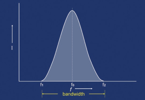
The frequency spread of an ultrasound pulse is called the bandwidth. A pulse transmitted at a centre frequency (f0) would also contain frequencies from f1 to f2.
Harmonics were initially used with contrast agents, however it was soon discovered that harmonic frequencies were generated during the passage of the ultrasound beam through tissue. When the compression wave of a pulse leaves the transducer, it is sinusoidal. Then, as it passes through tissue, it undergoes some distortion (Figure 2). In other words it changes shape. This distortion occurs because as the wave compresses the tissue, the speed of sound in the compressed tissue increases a little and the wave travels slightly faster. In the rarefied (or low compression) area of the wave, the speed of sound is a little lower and the wave travels slightly slower. When the wave distorts in this way, other frequencies develop in the wave. These are the harmonic frequencies.
Figure 2.
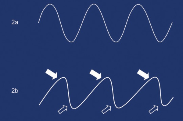
The ultrasound pulse starts out with a sinusoidal waveform (2a). As the wave passes through tissue (2b), the wave speeds up very slightly during the compression phase (solid arrows) and during the rarefaction phase the wave slows slightly (open arrows). This causes a distortion of the wave and crea tes the ha rmonic frequencies.
Echoes that return from the patient are a mirror image of the pulse, so the echoes also have the distortion, and therefore the harmonic frequencies. Harmonics are frequencies at multiples above the fundamental frequency – the frequency that was emitted from the transducer. (Note that the fundamental frequency is also known as the first harmonic 2 , 3 and these terms are used interchangeably). For example, if the pulse is transmitted at 3 MHz (the fundamental frequency), each returning echo will consist of a 3 MHz frequency (with its inherent bandwidth) as well as a 6 MHz frequency (the second harmonic). This second harmonic frequency will also have an inherent bandwidth of frequencies (Figure 3). The pulse also generates higher harmonic frequencies (e.g. 9 MHz and 12 MHz), however these high frequencies are attenuated significantly in the tissue and are not utilised.
Figure 3.
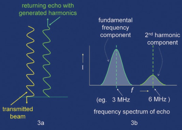
Transmitted and reflected wave shapes (3a) and a graph showing the frequency spread in returning echoes from a 3 MHz pulse (3b). The 2 MHz fundamental frequency component and the 6 MHz second harmonic component each have an inherent bandwidth.
The fundamental and second harmonic frequencies are not separate – they are combined as a complex (distorted) wave. When THI is turned on, the electronics of the machine removes the fundamental frequency component and leaves the second harmonic frequency which is then used to form the image.
For useable levels of harmonics to be generated, two things need to happen:
The pulse must travel some distance through the tissue to generate the distortion.
The pulse must have relatively high intensity.
Figure 4a shows a typical ultrasound beam with side lobes and a representation of the harmonic frequency profile. Note that the harmonics are generated in the high intensity central part of the beam. They are not generated to any degree in the weak intensity side lobes or in the lower intensity edges of the beam. The transducer also receives a moderate amount of backscatter caused by scattered echoes within the beam interacting with scatterers in adjacent tissue (Figure 4b). These backscattered echoes are very low intensity and do not generate any significant harmonics. When THI is activated, only the harmonic frequency component is detected, greatly improving the beam profile (Figure 4c). The side lobes (and their potential artifacts) disappear, the beam effectively becomes narrower which results in improved lateral resolution and the removal of much of the backscatter improves the signal to noise ratio (SNR) thus improving contrast resolution. Also, because the beam becomes narrower in the orthogonal plane as well as the scan plane, slice thickness is reduced which further improves contrast resolution (Figure 5).
Figure 4.
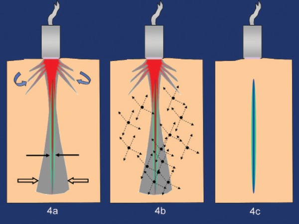
Ultrasound beam at the fundamental frequency (open straight arrows) with its side lobes (curved arrows) and the generated second harmonic frequency profile (solid arrows) (4a). Multiple low intensity scattered beams occur throughout the tissue (4b). When THI is activated, the fundamental frequency is removed leaving only the harmonic frequency (4c).
Figure 5.
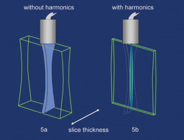
An ultrasound beam is much thicker in the orthogonal plane than in the scan plane which results in a relatively large slice thickness (5a). When THI is activated, the beam becomes narrower in all planes which results in a thinner slice (5b).
The fundamental frequency can be removed by several different methods:
Bandwidth filtering
Pulse inversion harmonics
Coded harmonics
Differential harmonics.
Filtering
In the early stages of harmonic development, the returning echoes went through a relatively simple frequency filter, which removed the fundamental frequency and its associated bandwidth frequencies. Modern ultrasound machines now generate very short pulses (which improves axial resolution), however a short pulse creates a very wide bandwidth. This causes significant overlap of the fundamental and harmonic frequencies (Figure 6).
Figure 6.
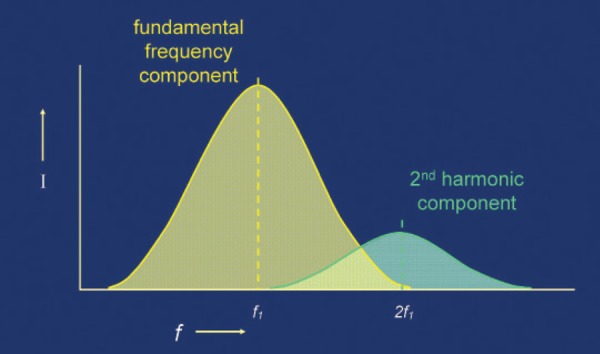
The increased bandwidth from the very short pulses of modern ultrasound machines causes a large overlap of the fundamental and 2nd harmonic frequencies.
The simple filtering method cannot be used to remove the fundamental frequency because it would remove a large part of the second harmonic frequency component as well. This problem could be overcome by increasing the pulse length when THI is used (which reduces the bandwidth), however axial resolution would be degraded.
Pulse inversion
Pulse inversion harmonics is a clever way of avoiding the filtering problem. Two pulses are sent out for each beam path with the second pulse being 180° phase inverted to the first pulse. The second phase inverted pulse is therefore completely opposite in phase to the first pulse. The echoes from each of the pulses are stored by the computer and then analysed. Because the echoes are mirror images of the pulses, the two sets of echoes are also phase inverted. The computer then adds the two sets of echoes. If harmonic distortion had not occurred, the two echoes would undergo destructive interference and cancel (Figure 7a). However, because the returning echoes are distorted, they will not add up to zero. The result of this addition will produce the harmonic frequency (Figure 7b).
Figure 7.
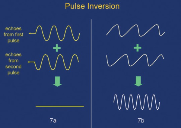
If no harmonic distortion of the waves had occurred, the two phase inverted echoes would cancel each other out (7a). Because the waves are distorted, they are not exact mirror images of each other so that when they are added, a resultant frequency remains (7b). This is the harmonic frequency component of the wave.
In simplistic terms, the two inverted fundamental frequencies have been added, cancelled each other out and removed from the final result. What remains is the result of the distortion – the harmonic frequencies. The advantage of this technique is that the wide bandwidth of the short pulses is not a problem. However it has the disadvantage that two pulses are required for each echo set which reduces the frame rate resulting in degraded temporal resolution. Also, if there is any movement of a reflector between the pulses, the fundamental frequency is not completely removed. 04
Coded harmonics
With coded harmonics, a unique code is applied to the pulses using either binary or FM Chirp encoding.
Binary encoding involves the application of a sequence of wavelengths with a binary signature (Figure 8b) while with FM Chirp encoding, the frequency of the pulse emitted from the transducer is increased at a specific rate during the generation of the pulse itself (Figure 8c).
Figure 8.
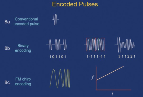
An uncoded pulse (8a). Examples of three different methods of applying a binary code to a pulse (8b). An FM Chirp encoded pulse and a graph of the unique rate of frequency increase for that pulse (8c).
It has been shown that FM Chirp encoding is the code type more suited to harmonic imaging. 05
Pulse encoding enables the fundamental frequency to be isolated and then subtracted from the returning echo rather than filtered out which permits the use of short pulses with their inherent wide bandwidth.
A combination of Chirp pulse encoding and pulse inversion will further improve the SNR and therefore enhance the harmonic image. 06
Differential harmonics
Differential harmonics is another approach used to separate the fundamental frequency. Two specific frequencies are contained within each pulse. It can be shown mathematically that the returned echoes contain frequencies at the sum and difference of the transmitted frequencies as well as their harmonics 03 (Figure 9). The two lower frequency components of the echo are used in the image production process. Using a technique similar to pulse inversion, the fundamental frequency is able to be subtracted from the returning echoes which avoids the problems with filtering.
Figure 9.
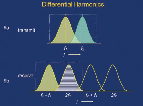
Transmission of two discrete frequencies in a single pulse (9a). Complex frequency profile of the returning echoes. The two lower frequency components are used for image production (9b).
Discussion
Within this article's description of harmonics, the following physics principles have been mentioned: basic wave physics, beam profile, beam intensity variation, lateral resolution, axial resolution, contrast resolution, temporal resolution, bandwidth and side lobes. Without knowledge of these principles, it is not possible to have a full understanding of how the various forms of harmonics work and therefore the advantages and limitations of the type that is installed on the machine that is being used.
Which is the best type of harmonics to have on a machine? It is an interesting question and unfortunately there may not be an available choice. The decision on which machine to acquire is based on many factors including cost, range of features, ease of use, image quality, upgradeability and compatibility with other department equipment. A lower cost, more basic machine might only have simple harmonics with bandwidth filtering. A mid or top range machine would almost certainly come with more advanced harmonics. What is more important is that user needs to know what type of harmonics is on the machine, understand the basics of how it works and appreciate any limitations it might have. For example, if it is required to achieve high frame rates for an examination, then pulse inversion techniques will compromise the maximum achievable rate. Therefore it might be beneficial to switch off THI to optimise frame rate with certain examinations. However if the machine has multiple beamformers that enable several scan lines to be acquired simultaneously, then frame rates may well be more than adequate. If the machine has simple (bandwidth filtered) harmonics, it needs to be remembered that that there may be a trade‐off with axial resolution when THI is activated.
Conclusion
One would think that the highly automated modern ultrasound machines would reduce the necessity for users to have in‐depth knowledge of the principles of the machine's functions. However the increased automation has the potential of producing a degree of complacency in sonologists and sonographers resulting in a reduction of their knowledge required to make manual adjustments for increasing the diagnostic quality of the images, particularly with a challenging patient. This discussion has looked at only one of ultrasound's more recent developments and it is apparent that without a high level of understanding of basic ultrasound principles, users are limited in their ability to make informed decisions on the use of this feature. Also, there are many other features in use or being developed such as encoded pulses that enable blood flow to be visualised with grey scale imaging, extended field of view imaging, elastography, compound imaging, image fusion and microbubble therapy. To understand the advantages and limitations of these features, their principles need to be understood and this cannot be done without sound background knowledge.
Is knowledge of ultrasound physical principles required as much today as was necessary in previous years? Yes – more than ever.
References
- 1. Carpenter D, Kossoff G, Garrett WJ, Daniel K, Boele P. The UI Octoson – A New Class of Ultrasonic Echoscope. Australas Radiol 1997; 21 (1): 85–89. [DOI] [PubMed] [Google Scholar]
- 2. Gill R. The Physics and Technology of Diagnostic Ultrasound: A Practitioner's Guide. Sydney: High Frequency Publishing; 2012. [Google Scholar]
- 3. Chiou S‐Y, Forsberg F, Fox TB, Needleman L. Comparing Differential Tissue Harmonic Imaging with Tissue Harmonic and Fundamental Gray Scale Imaging of the Liver. J Ultrasound Med 2007; 26: 1557–63. [DOI] [PubMed] [Google Scholar]
- 4. Tanabe M, Yamamura T, Kan ON. In: Tanabe M, editor. Tissue Harmonic Imaging with Coded Excitation, Ultrasound Imaging. Vienna: InTech, 2011. [Google Scholar]
- 5. Arshadi R, Yu AC, Cobbold RS. Coded Excitation Methods for Ultrasound Harmonic Imaging. Can Acoust 2007; 35 (2): 35–46. [Google Scholar]
- 6. Park J, Huang Y, Chen R, Lee J, Cummins TM, Zhou Q, et al. Pulse inversion chirp coded tissue harmonic imaging (PI‐CTHI) of Zebrafish heart using high frame rate ultrasound biomicroscopy. Ann Biomed Eng 2013; 41 (1): 41–52. [DOI] [PMC free article] [PubMed] [Google Scholar]


