Abstract
Three-dimensional (3D)-woven noncrimp fiber-reinforced composite (FRC) was tested for mechanical properties in the two principal directions of the main XY plane and compared to different Computer-Aided-Design/Computer-Aided-Machining (CAD/CAM) Dental Materials. The Dental Materials included ceramic with Vitablock Mark II®, ProCAD®, InCeram® Spinel, InCeram® Alumina and InCeram® Zirconia in addition to a resin-based 3M Corp. Paradigm® particulate-filled composite. Alternate material controls included Coors 300 Alumina Ceramic and a tungsten carbide 22% cobalt cermet. The 3D-woven FRC was vacuum assisted resin transfer molding processed as a one-depth-thickness ~19-mm preform with a vinyl-ester resin and cut into blocks similar to the commercial CAD/CAM Dental Materials. Mechanical test samples prepared for a flexural three-point span length of 10.0 mm were sectioned for minimum-depth cuts to compare machinability and fracture resistance between groups. 3D-woven FRC improved mechanical properties with significant statistical differences over all CAD/CAM Dental Materials and Coors Alumina Ceramic for flexural strength (p<0.001), resilience (p<0.05), work of fracture (p<0.001), strain energy release (p<0.05), critical stress intensity factor (p<0.001) and strain (p<0.001).
1. INTRODUCTION
1.1 CAD/CAM Dental Materials
Delamination encountered with two-dimensional (2D)-woven fiber-reinforced composite (FRC) can be counteracted to an extent with machinable noncrimp 3D-woven FRCs having high fracture-toughness properties and strengths [1–3]. Thus, 3D-woven FRCs are now considered as replacement for current Computer-Aided-Designing/Computer-Aided-Machining (CAD/CAM) Dental Materials [4–6]. CAD/CAM equipment can make crowns directly in the dental office [4–6]. Alternatively, a dental laboratory can fabricate crowns from working casts or digitally scanned data or an authorized milling center can make crowns from casts and/or digitally scanned data sent by the dental laboratory [4, 5]. Although milling fully sintered ceramic is exceedingly difficult and costly [4, 5] for in-office fabrication ceramics with lower mechanical properties are available as partially sintered to reduce milling time considerably and then subsequently glass infiltrated in an oven for increased strengths [4–6]. Also, fully-sintered ceramics and reported advanced alumina and zirconia ceramics with higher mechanical properties are further machined at authorized milling centers to accommodate difficult machining of such high-wear-resistant material [4, 5]. However, fully sintered alumina or zirconia can be difficult to mill requiring up to 3 hours for an underlying coping that is subsequently laminated with a low strength porcelain cover for esthetic reasons and reduce wear of the opposing dentition [4, 5].
1.2 Problems with Ceramic Materials
In addition to exceedingly high wear-resistant properties that makes machining of sintered ceramic difficult [5, 6], several other common problems occur with ceramic material. Brittle fracture from contact loading is a major failure mechanism for ceramics with rapid crack propagation before plastic deformation occurs [7]. Ceramic fracture by premature failure is identified by a classic brittle means with fracture outside the contact ring perpendicular to developed stresses [7–9] and a second failure from shear stresses below the contact with crack propagation by breaking atomic bonds and cleaving grains in planar fashion [7, 8]. Further, extremely small flaws act as stress concentrations that amplify applied force loadings to be active as locations for crack initiation [7, 10]. Subsequent surface/subsurface milling defects then limit the degree of how fine ceramics can be machined due to a reduction in material strength [10–15]. Even large changes in ceramic thickness or shape can cause stress raisers so that sharp internal line angles should be rounded [10] such that rounded chamfer margins have even been suggested to replace the common sharp shoulder ceramic margins [16]. Slow crack growth propagation can occur by moisture or other chemical means [7, 17] in addition to repetitive mechanical loading [17] that can increase ceramic fracture. Fracture and chipping of dental ceramic restorations is well-known [16, 18–23] and particularly evident in the posterior areas from higher mechanical forces [13, 19–23]. In addition, ceramic bulk thickness has been shown to correlate with the actual material strength during a ceramic load testing fracture-resistance trial, R2 = 0.9643 [24]. As a result, bulky ceramic restorations require aggressive tooth reductions that commonly cause pulpal pain and death [21, 25]. Pulpal death caused from ceramic tooth preparations abound to such an excessive extent that Endodontic therapy is often recommended before preparing ceramic crowns as root canal access for treatment can result in brittle ceramic fracture and require fabrication of a new restoration [21]. The destructive nature of ceramic brittle failure is so unforeseen that a resin-modified-reinforced-glass-ionomer cement luting agent designed only to counteract polymerization cure shrinkage from hygroscopic expansion by adsorbing water could produce stresses higher than ceramic strength thus becoming responsible for a high incidence of several post-cementation crown fractures [26]. During flexural testing of ceramic samples the strain energy release (SIc) at critical load is a measure of the surface energy of both fracture surfaces formed [27]. However, the majority of energy is stored in the bulk of the sample and released at such high velocity that crack propagation continues by breaking atomic bonds through the full ceramic sample for complete fracture and may even lift the brittle ceramic sample up off the platen of the test fixture while loading [27]. Further, ceramics are exceedingly difficult to repair requiring mechanical retention grooves or undercuts including acid etching with silane coupling [28]. Zirconia is particularly inert as a ceramic material to adhesive bonding so that problems with cementation are common that require good coping retention and resistance form [5, 29, 30].
1.3 Polymer Matrix Composites
Regarding another option for Dental Materials, polymer-matrix FRCs are associated with high-fracture toughness properties and strengths further related to structural applications [27, 31–34]. In fact, in a three-year CAD/CAM dental clinical study, the relatively low-strength polymer-matrix particulate-filled CAD/CAM composite Paradigm® had no fracture compared to 4 fractures for Cerec Mark II® ceramic [35]. In addition, polymer interfaces have been extensively studied for cost-effective repair, bonding and structural joining [36, 37]. Further, polymer-matrix FRC has even demonstrated high tissue biocompatibility [38]. Although isotropic brittle materials such as ceramics exhibit complete fracture through on flexural test samples, FRCs generally do not exhibit fracture through the full sample due to energy adsorption mechanisms by lateral crack deflections, fiber pull-out and fiber bridging [27, 31, 33].
1.4 Test Design
In order to better determine the advantages of 3D-woven FRCs, several common CAD/CAM Dental Materials were further evaluated by flexural mechanical testing to include: Vitablock Mark II®, 3M Corp. Paradigm® composite, ProCAD®, InCeram Spinel®, InCeram Alumina® and InCeram Zirconia® in addition to a Coors 300 Alumina industrial control. Tungsten carbide (WC) cermet with 22% cobalt binder was also included for comparisons in addition to 3M Corp. Z100® particulate-filled photocure dental composite and Kerr Tytin® Regular amalgam. Marginal error of significance was set at α = 0.05.
2. EXPERIMENTATION
2.1 Materials
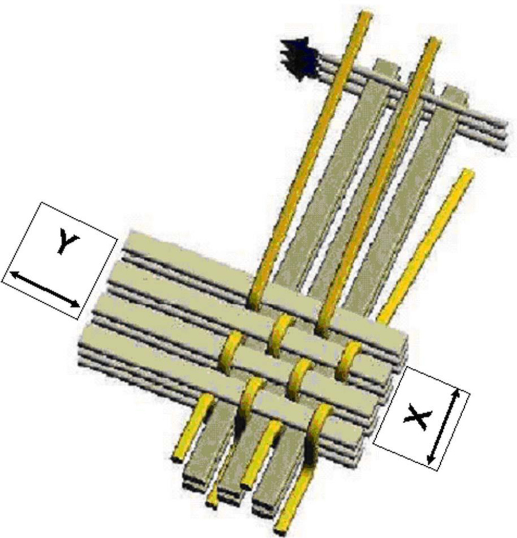
3D weave ~19-mm-thick preform material (3TEX, Cary, NC now Saertex, Huntersville, NC) constructed with PPG 2022 Hybon E-glass fiber (PPG, www.ppgfiberglass.com) was infused with bisphenol vinyl-ester-dimethacrylate resin or 2,2-bis [p-(2′hydroxy-3′-methacryloxypropoxyphenyl)] propane (Bis-GMA) and approximate 45% styrene (Derakane, Ashland Chemical, TN) with 1.0% Trigonox cumyl peroxide initiator oxidizing agent (Akzo Nobel Polymer Chemicals, Chicago, IL) with 0.3% cobalt naphthenate reducing agent accelerator (Sigma Aldrich, St Louis, MO). Fabrication included vacuum assisted resin transfer molding (VARTM) (3TEX, Rutherfordton Plant, PA, now Saertex, Huntersville, NC). Fiber volume percents (Vfs) were as follows with Figure 1:
Vfx = 25.3% (warp direction, aligned with top Z fibers)
Vfy = 25.8% (fill direction, uppermost and lower most straight fibers)
Vfz = 2.1% (through the thickness)
Figure 1.
Illustration of 3 Weave® XY plane fiber directions with Z-fibers parallel to the X fiber direction and looping over the Y fibers. The total woven Vf of the composite is approximately 53.2% with 46.8% air. But, following VARTM densification the total Vf increases to an approximate 56% with the polymer fraction about 44%. [39-Stobbe D and Mohamed M (2003) A New Generation of 3D Woven Fabric Preforms and Composites. SAMPE Journal Vol 37, No. 3 May/June: 8–17, Figure 1. Reprinted by permission from the Society for the Advancement of Material and Process Engineering (SAMPE)].
Commercial CAD/CAM Dental Materials tested supplied as blocks included feldspathic Vitablock Mark II® (Vita Zahnfabrik, Bad Sackingen, Germany), resin-based particulate-filled composite Paradigm® (3M Corporation, St. Paul, MN, USA), leucite-reinforced ProCAD® (Ivoclar Vivadent, Schaan, Liechtenstein), Vita InCeram Spinel® magnesium oxide (Vita Zahnfabrik Sirona, Bad Sackingen, Germany), Vita InCeram Alumina® (Vita Zahnfabrik Sirona, Bad Sackingen, Germany) and Vita InCeram Zirconia® (Vita Zahnfabrik Sirona, Bad Sackingen, Germany). Vita InCeram are manufactured as blocks by dry pressing the powder into a mold to provide an open pore structure that can be rapidly CAD/CAM machined in-office and subsequently sintered and glass infiltrated. Standard industrial materials were further tested for comparison using BC22C WC cermet 22% cobalt (Basic Carbide, Buena Vista, PA); and Coors AL 300 alumina, (Coors Ceramic, Golden, CO); in addition more comparison material as Tytin® Regular Amalgam 600-mg capsules (Kerr, Orange, CA) supplied with spherical particulate and 42.5%-mercury (Hg) were triturated according to manufacturer instructions and compacted into a test mold with an electronic condenser for 48 hour set; and laboratory-preparation particulate-filled photocure composite (Z100® zirconia-silicate particulate, 3M Corporation, St. Paul, MN).
2.2 Samples
3D-woven FRC blocks were cut down into CAD/CAM cubes and final samples were prepared with an Isomet circular precision-sectioning saw. Machinability for the 3D-wovern FRC was considered for Dental CAD/CAM materials comparisons from the small commercial ceramic blocks by testing sample depth under approximately 1.0 mm over a 10 mm flexural test span for the XY plane in both the principal X and Y directions. For better machinability comparisons between the 3D-woven FRC and ceramic/cermet samples, material planar depth was incrementally stepped from 0.25-mm outward with the precision circular Isomet saw until a full specimen could also be cut in the width direction without fracture. Tytin® amalgam silver alloy and Z100® particulate-filled photocure composite Dental Material controls were tested instead by 4-point bend as 2.0-mm X 2.0-mm samples across a 40-mm span with fully-articulating fixtures [27, 31–34].
2.3 Mechanical Testing
2.3.1 Fixtures
Three-point bend fixtures with 10-mm span length were used to test four samples from each group except for the 3D-woven FRCs where 3 samples each were tested from the XY plane by preparing samples longitudinally in both major X and Y directions of stress, Figure 1, for a total of 6 specimens.
2.3.2 Mechanical Test Machine
An MTS inspection machine (858 MiniBionix) with a crosshead speed of 0.5 mm/minute was used to mechanically test flexural properties by Equations 1 and 2.
| [1] |
| [2] |
Specifying F-maximum load, L-span length, b-sample width, d-sample depth and M-slope of the tangent to the initial straight line on steepest part of the load-deflection curve [7].
2.3.3 Load-Deflection Data and Numerical Integration
Work of Fracture (WOF) in kJ/m2 units: energy was integrated by numerical methods [31, 33] from the load-deflection curve out past critical load to a maximum of 5% deviation past peak load for cross-sectional area toughness.
Resilience in kJ/m2 units: energy was integrated by numerical methods [31, 33] from the load-deflection curve in the elastic region up to yield point where the initial steep straight-line slope deviates toward increased deflection for cross-sectional area toughness.
Strain Energy Release (SIc) in kJ/m2 units: Crack-propagation energy was integrated by numerical methods for area during Mode I (I) Euler tensile flexural bending under the load deflection curve from peak or critical load (c) to a maximum of 5% deviation past peak load. SIc toughness is then a function of energy relative to the material cross-sectional area [27, 31, 33].
Critical Stress Intensity Factor (KIc): KIc in MPa*m1/2 units can be derived by direct integration methods from the load deflection curve by Equation 3 where common excessive correction factors are replaced by real-data-calculated values for the WOF and maximum strength functions that serve the same purpose [27] whereby:
| [3] |
Further signifying a as the surface crack tip length or half the internal crack length, 𝒢Ic as stress energy release rate equivalent to SIc and Y as a correction factor for crack initiation described in accuracy as the product of the square root for strength and WOF with more detail Equation 4 [27] so that:
| [4] |
As a result, KIc is a measure of material resistance to fracture when a crack is present [7]. The convenience of real-data bulk-material values easily calculated from the common load-deflection curve are then available without suspect Y correction factors from simple load-cell testing greatly criticized by the United States National Academy of Sciences as not providing bulk-material results [40]. In related response since strength is inherent toward fracture toughness MIL STD 1942(MR) military specifications for brittle materials was established using four-point flexural fixtures for strength and modulus [41].
2.3.4 Strain (r)
| [5] |
Where r is maximum strain in the outer fibers at midspan on the tensile surface at maximum load and D is sample beam deflection as digitally provided at maximum bend strength by Equation 5.
2.4 Statistics
Statistica software calculated post-hoc ANOVA Newman-Keuls comparisons (α=0.05) and Microsoft Excel for chart figures. Significant statistical differences (SSDs) were then considered to occur when probability (p) values for error in asserting that such differences do in fact exist were at a marginal level of uncertainty with p <.05.
3. RESULTS
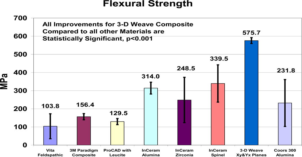
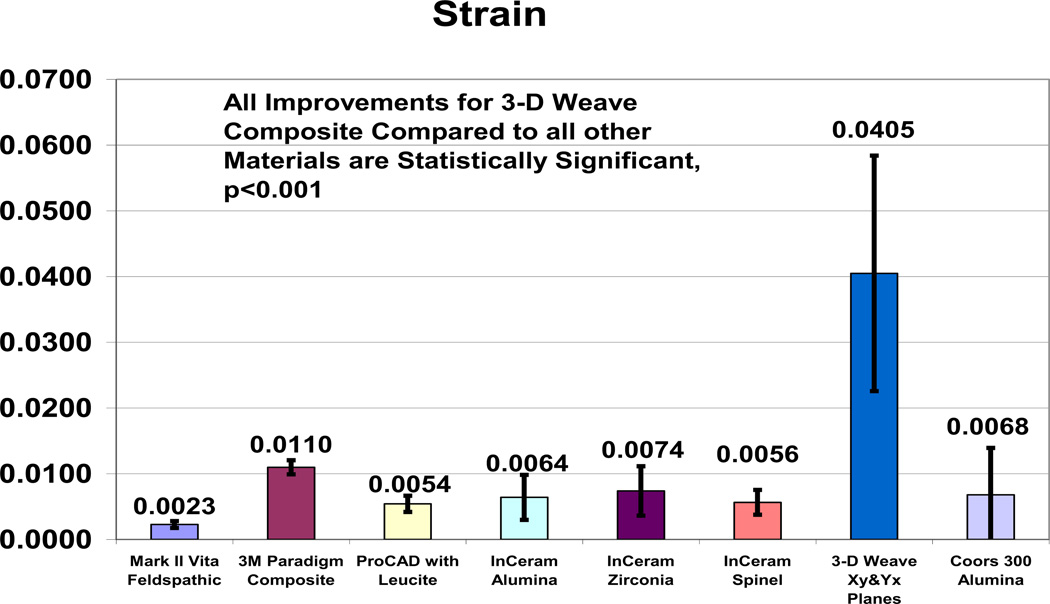
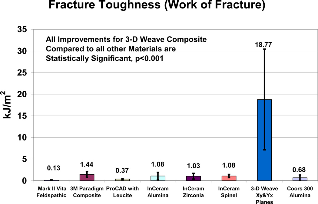
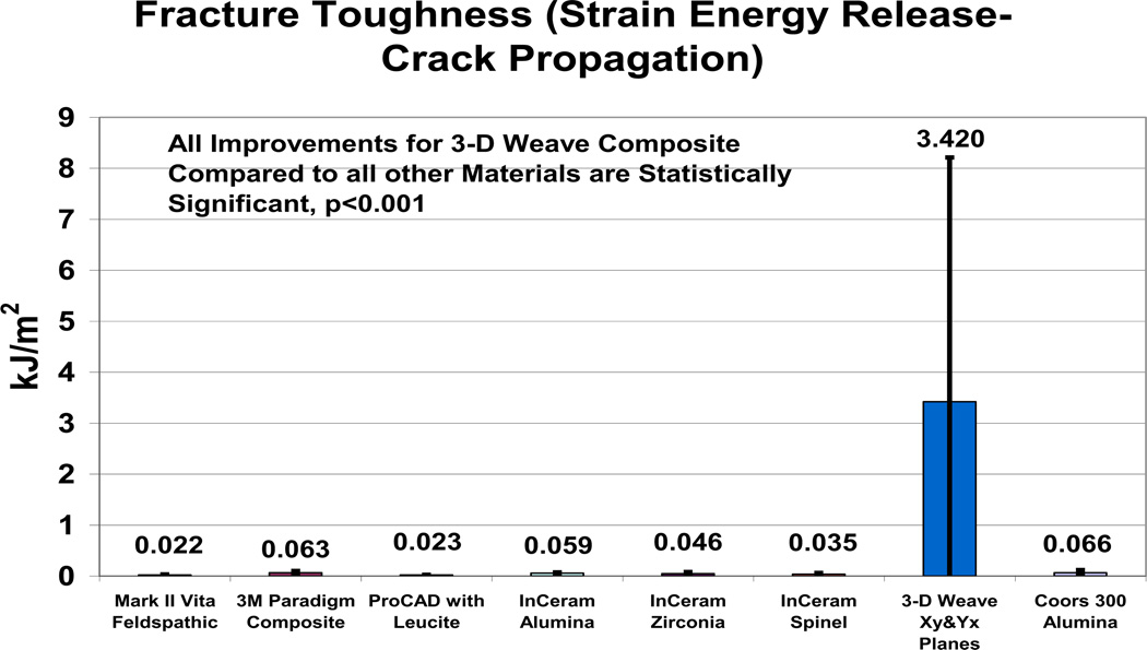
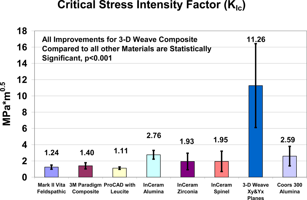
Results for the sample precision saw-cut depth and mechanical properties tested are presented in Table 1 and Figures 2–6. Tungsten Carbide control set the minimum standard for sample thickness of all materials tested at 0.364 ± 0.013 mm. The 3D-woven FRCs had an average sample depth of 0.49 mm and all other materials required samples depths ranging from 0.70 mm to 1.16 mm. FRC samples were all still intact after mechanical testing whereas all other samples broke through completely with at least two cleaved fracture surfaces. 3D-woven FRC improved mechanical properties with SSDs over all CAD/CAM Dental Materials and Coors Alumina for flexural strength (p<0.001), resilience (p<0.05), WOF (p<0.001), SIc (p<0.05), KIc (p<0.001) and strain (p<0.001). WC alternative material control produced highly SSDs by increasing mechanical properties above all other materials for flexural strength, modulus and KIc p<0.001 and WOF for all ceramics p<0.01. On the other hand, 3D-woven FRC was able to produce SSDs above WC for both WOF p<.05 and strain WOF p<.001. Error bars as ± one standard deviations. Comparisons for human tooth mechanical properties are shown in Table 2.
Table 1.
Mechanical Properties and Sample Thickness (±standard deviations in parentheses) {Strength and KIc literature values in brackets}
| Material | Sample Thickness (mm) |
Flexural Strength (MPa) |
Modulus (GPa) |
Resilience (kJ/m2) |
WOF (kJ/m2) |
SIc (kJ/m2) |
KIc (MPa*m1/2) |
|---|---|---|---|---|---|---|---|
|
3D-Weave Xy and Yx |
0.49 (±0.19) |
575.7 (±129.1) |
24.6 (±15.7) |
5.57 (±2.38) |
18.77 (±11.63) |
3.420 (±4.793) |
11.26 (±5.16) |
|
Vita Mark II |
0.70 (±0.15) |
103.8 (±17.0) {105–150}[4,42,43] |
46.6 (±4.3) |
0.1 3 (±0.04) |
0.1 3 (±0.04) |
0.022 (±0.008) |
1.24 (±0.25) {0.8–1.25}[12,44,45] |
|
MZ100 Paradigm |
0.94 (±0.10) |
156.4 (±16.8) |
12.2 (±2.0) |
1.44 (±0.69) |
1.44 (±0.69) |
0.055 (±0.036) |
1.40 (±0.40) |
|
ProCAD Leucite |
1.16 (±0.20) |
129.5 (±32.4) {120–150}[4.42.43] |
26.2 (±5.8) |
0.37 (±0.14) |
0.37 (±0.14) |
0.023 (±0.002) |
1.11 (±0.14) |
|
InCeram Spinel |
1.02 (±0.18) |
339.5 (±16.1) {350}[4,42] |
65.5 (±22.5) |
1.08 (±0.37) |
1.08 (±0.37) |
0.035 (±0.024) |
1.95 (±1.25) |
|
InCeram Alumina |
0.86 (±0.19) |
314.0 (±124.9) {500–550}[4.43.46] |
63.8 (±25.3) |
1.08 (±0.85) |
1.08 (±0.85) |
0.059 (±0.014) |
2.76 (±0.54) {2.46–3.0}[12,46] |
|
InCeram Zirconia§ |
1.06 (±0.29) |
248.5 (±102.7) {440–750}[4,43,46] |
39.0 (±21.6) |
1.03 (±0.66) |
1.03 (±0.66) |
0.046 (±0.034) |
1.93 (±1.02) {3.5}[46] |
|
Coors AL300 |
0.82 (±0.30) |
231.8 (±71.7) |
79.6 (±31.2) |
0.68 (±0.64) |
0.68 (±0.64) |
0.066 (±0.051) |
2.59 (±1.20) {3.25–3.4}[45,47] |
|
Tungsten Carbide |
0.36 (±0.01) |
2278.8 (±40.8) {1620–2320}[48] |
253.9 (±16.2) |
13.46 (±0.56) |
13.46 (±0.56) |
0.279 (±0.005) |
15.68 (±0.14) {12.0}[48] |
|
Z100 Particle Composite |
2.05 (±0.13) 4pt bend |
117.6 (±5.45) |
19.5 (±1.3) |
4.48 (±0.41) |
4.48 (±0.41) |
0.036 (±0.023) |
1.71 (±0.30) {1.4}[49] |
|
Amalgam Alloy [50] |
2.11 (±0.11) 4pt bend |
86.0 (±10.6) |
43.6 (±6.1) |
1.40 (±0.28) |
1.40 (±0.28) |
0.013 (±0.012) |
0.91 (±0.52) |
Figure 2.
Mechanical Properties for Flexural Strength.
Figure 6.
Mechanical Properties for Strain.
Table 2.
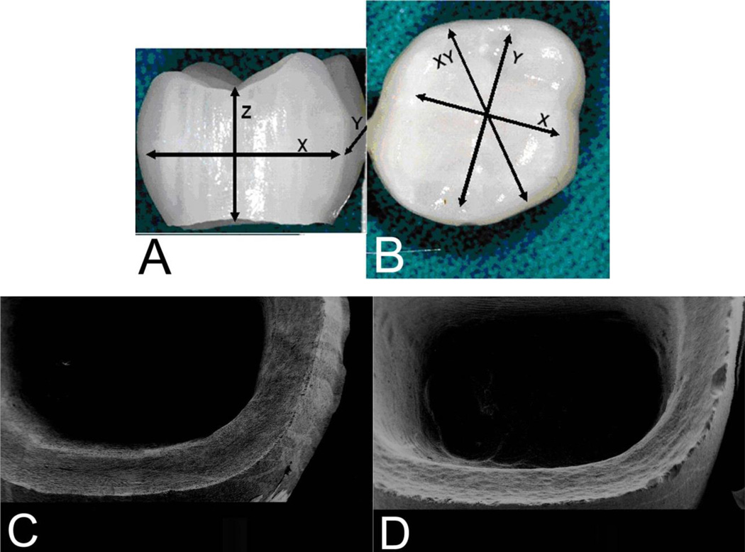
Photos of CEREC® in-office milled FRC crown from 3rd generation 3D-woven material with new resin and stacked laminate preform design, Figures 7A–7B. Milling of FRCs is highly efficient when compared to ceramics and especially advanced ceramics as costs associated with grinding can be 80% or greater of the total costs [53]. Nevertheless, efforts to lower ceramic costs by increased grinding rates have produced increased strength-reducing surface flaws [53]. Further, machinability of ceramics is associated with chips and grinding striations not seen with FRCs that mill much smoother seen with scanning electron micrographs (SEMs), Figure 7C–7D.
Figure 7.
A–B. Photos of FRC CAD/CAM in-office milling with CEREC® 3D diamond tooling without polishing for a full crown took about 15 minutes compared to 20 minutes for partially sintered ceramic and 40 minute glass infiltration or 3 hours machining for fully sintered single unit Ceram coping. C. SEM FRC smooth crown margins. D. SEM ProCAD® ceramic flaws.
4. DISCUSSION
3D-woven FRC appears to have many important advantages over the CAD/CAM ceramics tested in terms of machinability time/costs/smoothness and mechanical properties for strength, fracture toughness and strain. In addition 3D-woven FRC tested for a modulus between dentin and enamel [12, 50, 51] that might provide better biocompatible stress transfer with the whole tooth and underlying bone. Further, strain is an approximate order of magnitude higher than ceramics to help maintain stable stress states under yield. In fact, 3D-woven FRC values for strength-type properties and KIc, are extensively higher than for dentin or enamel, [12, 51, 52] as another measure for projected clinical applications. Also, long-term occlusal chewing loads are expected to be generally below related stresses for strength with a standard amalgam filling material, 86 MPa flexural strength, that is the lowest of all materials tested, Table 1 [50], for additional 3D-woven FRC application to restore large cavities. A chief gauge for full crowns is ISO standard 1562 with type 2 or 3 gold alloys (2002) of 180–270 MPa minimum yield strength (0.2% offset) and 10-5% elongation [10]. By comparison, 3D weave vinyl ester FRC yield strength was tested for 441.3 ± 74.5 MPa and approximately 4% elongation. In terms of brittle failure, ceramic crowns tested for yield strength identical to maximum strength with essentially no yield from 104–340 MPa and with elongation the highest value tested for a ceramic was a value of just 0.74%. Further, 3D weave FRC can be tooth colored white, modified on the surface for esthetic shade/color bonding with a commercial-type kit for veneers. Also, the inside of FRC crowns can be adhesively bonded for reline adjusted to a perfect margin and fit without errors from impression, stone model, wax crown, investment or melted gold dimensional changes with a metal cast crown. Conversely, interfaces for all current crowns and teeth are admitted to have some gaps that require various forms of sealing with luting cements [54]. Increased marginal gaps between the tooth and crown can prevent adequate sealing to allow oral fluid adsorption and microleakage into the cements that in turn start to dissolve so that bacterial infiltration can eventually occur [54, 55].
Average sample precision-saw-cut depth results indicate that 3D-woven FRCs can be cut to thinner dimensions than all CAD/CAM Dental Materials tested. Circular-blade-saw cuts probably accentuated overall surface defects along an entire plane to reduce such ceramic mechanical properties. Further, machinability for thinner sections with FRCs over ceramic samples provides easy analysis that ultimately should be reflected by lower crown/tooth marginal-gap discrepancies for the FRCs. 3D-woven FRCs with much higher strength and fracture-toughness properties than the ceramics tested supply sufficient energy adsorption so that crack propagation related to brittle-fracture machining surface-damage is minimal. Conversely, lower test mechanical property values for the ceramics are probably related in part to the minimum sample depth dimension preparations combined with milling surface defects as part of the experimental design. Further, higher mechanical properties for FRCs over ceramics could allow milling of thinner dimensions for CAD/CAM crowns so that less tooth structure needs to be removed with less pain or pulpal exposure. From manufacturer laboratory-related development, machining FRCs costs were less than half for the ceramics. Also, machinability for ceramics is associated with flaws not seen with much smoother milled 3-D woven FRCs.
One of the most obvious problems with ceramics is with poor contact loading due to brittle fracture-toughness properties. Brittle fracture of all materials other than the 3D weave FRC is reflected in identical ceramic values for resilience and WOF with yield point the same as maximum strength. Conversely, 3D weave FRC had a yield point with plastic deformation before maximum strength occurred. Ceramic brittleness thus also necessitates rounding plane-intersecting line angles for dental-crown preparations [10, 16]. Subsequent stress concentrations or sharp line angles on the other hand will not be a major problem with the 3-D-woven FRC so that mechanical retention can be designed better into the dental crown. In fact, the 3D composites can adsorb more energy/area before maximum load and after critical crack propagation than the ceramics providing complete higher fracture toughness values over the entire load-deflection curve. Even the tungsten carbide control, well known for exceptional mechanical properties to include one of the hardest materials known, could be compared generally lower to the 3D-Woven FRC for three fracture-toughness properties with strain energy release over 10X lower and strain at maximum loading about 4X lower. Wear for FRC Dental Materials can already be designed to be even lower than enamel where fiber-wear thinning during wear produces smooth surfaces not expected to damage opposing tooth structure [56].
5. CONCLUSIONS
Perhaps most importantly, when designed properly highly brittle ceramic-type contact loading fracture failure will not be a problem with the future 3D-woven FRCs because of much higher fracture toughness properties. Further, increased flexural strength and ability to mill thinner sections will allow less tooth reduction for the crown with less projected pulpal pain or death. Also, milling times, grinding costs and machining flaws for FRCs are considerably less than ceramics.
Figure 3.
Mechanical Properties for Work of Fracture.
Figure 4.
Mechanical Properties for Strain Energy Release.
Figure 5.
Mechanical Properties for Critical Stress Intensity Factor.
Acknowledgments
National Institutes of Health Training Grant T32DE014300. Keith Sharp Consultation 3TEX Corporation now Saertex, Huntersville NC. Preston Beck SEMs, Biomaterials, University of Alabama at Birmingham.
REFERENCES
- 1.Brandt J, Drechsler K, Arendts F-J. Mechanical Performance of Composites Based on Various Three-Dimensional Woven-Fibre Preforms. Composites Science and Technology. 1996;56:381–386. [Google Scholar]
- 2.Lomov SV, Bogdanovich AE, Ivanov DS, Mungalov D, Karahan M, Verpoest I. A Comparative Study of Tensile Properties of Non-Crimp 3D Orthogonal Weave and Multi-Layer Plain Weave E-Glass Composites. Part 1: Materials, Methods and Principal Results. Composites: Part A. 2009;40:1134–1143. [Google Scholar]
- 3.Fishpool DT, Rezai A, Baker D, Ogin SL, Smith PA. Interlaminar Toughness Characterisation of 3D Woven Carbon Fibre Composites. Plastics, Rubber and Composites. 2013;42(3):108–114. [Google Scholar]
- 4.Liu P-R, Essig ME. A Panorama of Dental CAD/CAM Restorative Systems. Compendium. 2008;29(8):2–8. [PubMed] [Google Scholar]
- 5.Li RWL, Chow TW, Matinlinna JP. Ceramic Dental Biomaterials and CAD/CAM Technology: State of the Art. Journal of Prosthodontic Research. 2014;58:208–216. doi: 10.1016/j.jpor.2014.07.003. [DOI] [PubMed] [Google Scholar]
- 6.Baroudi K, Ibraheem SN. Assessment of Chair-Side Computer-Aided Design and Computer-Saided Manufacturing Restorations: A Review of the Literature. Journal of International Oral Health. 2015;7(4):96–104. [PMC free article] [PubMed] [Google Scholar]
- 7.Callister William D., Jr . Materials Science and Engineering. 4th. New York: John Wiley & Sons, Inc; 1997. [Google Scholar]
- 8.Peterson IM, Pajares A, Lawn BR, Thompson VP, Rekow ED. Mechanical Characterization of Dental Ceramics by Hertzian Contacts. Journal of Dental Research. 1998;77(4):589–602. doi: 10.1177/00220345980770041201. [DOI] [PubMed] [Google Scholar]
- 9.Lawn BR, Padture NP, Cai H, Guiberteau F. Making Ceramics Ductile. Science. 1994 Feb 25;263(5150):1114–1116. doi: 10.1126/science.263.5150.1114. [DOI] [PubMed] [Google Scholar]
- 10.Anusavice Kenneth J. Dental Materials. 11th. St. Louis: Elsevier Science; 2003. [Google Scholar]
- 11.Rekow ED, Silva NRFA, Coelho PG, Zhang Y, Guess P, Thompson VP. Performance of Dental Ceramics: Challenges for Improvements. Journal of Dental Research. 2011;90(8):937–952. doi: 10.1177/0022034510391795. [DOI] [PMC free article] [PubMed] [Google Scholar]
- 12.Lin L, Song XF, Song YL, Huang T, Li J. An overview of In Vitro Abrasive Finishing & CAD/CAM of Bioceramics in Restorative Dentistry. International Journal of Machine Tools and Manufacture. 2006;46:1013–1026. [Google Scholar]
- 13.Rekow D, Thompson VP. Near-Surface Damage-A Persistent Problem in Crowns Obtained by Computer-Aided Design and Manufacturing. Proceedings of the Institution of Mechanical Engineers 219 (Part H: J. Engineering in Medicine) 2005:233–243. doi: 10.1243/095441105X9363. [DOI] [PubMed] [Google Scholar]
- 14.Sindel J, Petschelt A, Grellner F, Dierken C, Greil P. Evaluation of Subsurface Damage in CAD/CAM Machined Dental Ceramics. Journal of Materials Science: Materials In Medicine. 1998;9:291–295. doi: 10.1023/a:1008812929476. [DOI] [PubMed] [Google Scholar]
- 15.Li K, Liao W. Surface/Subsurface Damage and the Fracture Strength of Ground Ceramics. Journal of Materials Processing Technology. 1996;57:207–220. [Google Scholar]
- 16.Jalalian E, Atashkar B, Rostami R. The Effect of Preparation Design on the Fracture Resistance of Zirconia Crown Copings (Computer Associated Design/Computer Associated Machine, CAD/CAM System) Journal of Dentistry. 2011;8(3):123–129. [PMC free article] [PubMed] [Google Scholar]
- 17.Zhang Y, Sailer I, Lawn BR. Fatigue of Dental Ceramics. Journal of Dentistry. 2013;41:1135–1147. doi: 10.1016/j.jdent.2013.10.007. [DOI] [PMC free article] [PubMed] [Google Scholar]
- 18.Andreiuolo RF, Sabrosa CE, Dias KRHC. Dual-Scan Techique for the Customization of Zirconia Computer-Aided Design/Computer-Aided Manufacturing Frameworks. European Journal of Dentistry. 2013;7(Supplement 1):115–118. doi: 10.4103/1305-7456.119088. [DOI] [PMC free article] [PubMed] [Google Scholar]
- 19.Silva NRFA, Bonfante EA, Rafferty BT, Zavanelli RA, Rekow ED, Thompson VP, Coelho PG. Modified Y-TZP Core Design Improves All-Ceramic Crown Reliability. Journal of Dental Research. 2011;90(11):104–108. doi: 10.1177/0022034510384617. [DOI] [PMC free article] [PubMed] [Google Scholar]
- 20.Kokubo Y, Sakurai S, Tsumita M, Ogawa T, Fukushima S. Clinical Evaluation of Procera AllCeram Crowns in Japanese Patients: Results After 5 Years. Journal of Oral Rehabilitation. 2009;36:786–791. doi: 10.1111/j.1365-2842.2009.01995.x. [DOI] [PubMed] [Google Scholar]
- 21.Donovan Terence E. Factors Essential for Successful All-Ceramic Restorations. Journal of the American Dental Association. 2008;139(Suppl 4):14S–18S. doi: 10.14219/jada.archive.2008.0360. [DOI] [PubMed] [Google Scholar]
- 22.Kim JH, Kim J-W, Myoung S-W, Pines M, Zhang Y. Damage Maps for Layered Ceramics Uncer Simulated Mastication. Journal of Dental Research. 2008;87(7):671–675. doi: 10.1177/154405910808700706. [DOI] [PMC free article] [PubMed] [Google Scholar]
- 23.McClaren EA, White SN. Survival of In-Ceram Crowns in a Private Practice: A Prospective Clinical Trial. Journal of Prosthetic Dentistry. 2000;83:216–222. doi: 10.1016/s0022-3913(00)80015-3. [DOI] [PubMed] [Google Scholar]
- 24.Gokce S, Celik-Bagci E, Turkyilmaz I. A Comparative In Vitro Study of the Load at Fracture of All-Ceramic Crowns with Various Thicknesses of In-Ceram Core. Journal of Contemporary Dental Practice. 2008;9(4):017–025. [PubMed] [Google Scholar]
- 25.Christiansen Gordon J. Overcoming Challenges With Resin in Class II Situations. Journal of the American Dental Association. 1997;128(11):1597–1580. doi: 10.14219/jada.archive.1997.0101. [DOI] [PubMed] [Google Scholar]
- 26.Leevalioj C, Platt JA, Cochran MA, Morre BK. In Vitro Study of Fracture-Incidence and Compressive Fracture Load of All Ceramic Crowns Cemented with Resin Modified Glass Ionomer and Other Luting Agents. Journal of Prosthetic Dentistry. 1998;80:699–707. doi: 10.1016/s0022-3913(98)70058-7. [DOI] [PubMed] [Google Scholar]
- 27.Petersen Richard C. SAMPE 2013 Proceedings. Long Beach, California: Society for the Advancement of Material and Process Engineering; 2013. May 6–9, Accurate Critical Stress Intensity Factor Griffith Crack Theory Measurements by Numerical Techniques; pp. 737–752. http://www.ncbi.nlm.nih.gov/pmc/articles/PMC4302413/ [PMC free article] [PubMed] [Google Scholar]
- 28.Melo RM, Valandro LF, Bottino MA. Microtensile Bond Strength of a Repair Composite to Leucite-Reinforced Feldspathic Ceramic. Brazilian Dental Journal. 2007;18:314–319. doi: 10.1590/s0103-64402007000400008. [DOI] [PubMed] [Google Scholar]
- 29.Kasraei S, Rezaei-Soufi L, Heidari B, Vafaee F. Bond Strength of Resin Cement to Co2 and Er:YAG Laser-Treated Zirconia Ceramic. Restorative Dentistry & Endodontics. 2014;39(4):296–302. doi: 10.5395/rde.2014.39.4.296. [DOI] [PMC free article] [PubMed] [Google Scholar]
- 30.Wang C, Niu Li-Na, Wang Y-J, Jiao K, Liu Y, Zhou W, Shen L-J, Fang M, Li M, Zhang X, Tay FR, Chen J-H. Bonding of Resin Cement to Ziroconia with High Pressure Primer Coatings. PLOS ONE www.plosone.org. 2014;9(7):e101174. doi: 10.1371/journal.pone.0101174. pages 1–8. [DOI] [PMC free article] [PubMed] [Google Scholar]
- 31.Petersen RC, Lemons JE, McCracken MS. Fiber Length Micromechanics for Fiber-Reinforced Composites with a Photocure Vinyl Ester Resin. Polymer Composites. 2006;27:153–168. doi: 10.1002/pc.20198. http://www.ncbi.nlm.nih.gov/pmc/articles/PMC4221241/pdf/nihms-587064.pdf. [DOI] [PMC free article] [PubMed] [Google Scholar]
- 32.Petersen RC, Lemons JE, McCracken MS. Micromechanics for Fiber Volume Percent with a Photocure Vinyl Ester Composite. Polymer Composites. 2007;28:294–310. doi: 10.1002/pc.20241. http://www.ncbi.nlm.nih.gov/pmc/articles/PMC4221239/pdf/nihms587068.pdf. [DOI] [PMC free article] [PubMed] [Google Scholar]
- 33.Petersen RC, Lemons JE, McCracken MS. Fracture Toughness Micromechanics by Energy Methods With a Photocure Fiber-Reinforced. Polymer Composites. 2007;28:311–324. doi: 10.1002/pc.20242. http://www.ncbi.nlm.nih.gov/pmc/articles/PMC4206059/pdf/nihms587070.pdf. [DOI] [PMC free article] [PubMed] [Google Scholar]
- 34.Chawla Krishan K, editor. Composite Materials Science and Engineering. 2nd. New York: Springer-Verlag; 1998. [Google Scholar]
- 35.Fasbinder DJ. Restorative Material Options for CAD/CAM Restorations. Compendium of Continuing Education of Dentistry. 2002;23(10):911–916. [PubMed] [Google Scholar]
- 36.Amaravadi VK, Mitchel K, Rao V, Derriso MM. Structural Integrity Monitoring of Composite Patch Repairs Using Wavelet Analysis and Neural Networks. Proceedings SPIE Smart Structures and Materials. 2002;4701:156–166. [Google Scholar]
- 37.Raghavan J, Wool RP. Interfaces in Repair, Recycling, Joining and Manufacturing of Polymers and Polymer Composites. Journal of Applied Polymer Science. 1999;71:775–785. [Google Scholar]
- 38.Petersen Richard C. Bisphenyl-Polymer/Carbon-Fiber-Reinforced Composite Compared to Titanium Alloy Bone Implant. International Journal of Polymer Science Polymeric Biomaterials for Tissue Engineering Applications annual focus/special issue Invited Paper. 2011 doi: 10.1155/2011/168924. located at http://downloads.hindawi.com/journals/ijps/2011/168924.pdf. [DOI] [PMC free article] [PubMed] [Google Scholar]
- 39.Stobbe D, Mohamed M. A New Generation of 3D Woven Fabric Preforms and Composites. SAMPE Journal. 2003 May-Jun;37(3):8–17. [Google Scholar]
- 40.National Materials Advisory Board. Reliability of Ceramics for Heat Engine Applications. Washington DC: National Academy of Sciences; 1980. Chapter 4 Materials Characterization. NMAB-357. [Google Scholar]
- 41.Quinn George D. Fractographic Analysis and the Army Flexure Test Method. Advances in Ceramics. 1988;22:319–333. [Google Scholar]
- 42.Ohyama T, Ikushima K, Akahane S. “Physical Properties of High-Dispersion Leucite Reinforced Glass Ceramic for CAD/CAM” (abstract) IADR General Session, Brisbane, Australia. 2006 Sequence #7 0064. [Google Scholar]
- 43.Liu Perng-Ru. A Panorama of Dental CAD/CAM Restorative Systems. Compendium. 2005;26:369–375. [PubMed] [Google Scholar]
- 44.Mansour YF, Mitchell CA. Journal of Dental Research 80 Special Issue AADR. 2001 Abstracts #570. [Google Scholar]
- 45.Marx R, Jungwirth F, Walter PO. Threshold Intensity Factors as Lower Boundaries for Crack Propagation in Ceramics. Biomedical Engineering OnLine. 2004;3:41–49. doi: 10.1186/1475-925X-3-41. Available from: http://www.biomedical-engineering-online.com/content/3/1/41. [DOI] [PMC free article] [PubMed] [Google Scholar]
- 46.Lawn BR, Pajares A, Zhang Y, Deng Y, Polack MA, Lloyd IK, Rekow ED, Thompson VP. Materials Design in the Performance of All-Ceramic Crowns. Biomaterials. 2004;25:2885–2892. doi: 10.1016/j.biomaterials.2003.09.050. [DOI] [PubMed] [Google Scholar]
- 47.Kruzic JJ, Cannon RM, Ager JW, Ritchie RO. Fatigue Threshold R-Curves for Predicting Reliability of Ceramics Under Cyclic Loading. Acta Materialia. 2005;53:2595–2605. [Google Scholar]
- 48.Acchar W, Gomes UU, Kaysser WA, Goring J. Strength Degradation of a Tungsten Carbide-Cobalt Composite at Elevated Temperatures. Materials Characterization. 1999;43:27–32. [Google Scholar]
- 49.Bonilla ED, Yashar M, Caputo AA. Journal of Prosthetic Dentistry. 2003;89:261–265. doi: 10.1067/mpr.2003.33. [DOI] [PubMed] [Google Scholar]
- 50.Petersen RC, Liu P-R. Mechanical Properties Comparing Composite Fiber Length to Amalgam. Journal of Composites In Press 682536. 2016 doi: 10.1155/2016/3823952. http://mts.hindawi.com. [DOI] [PMC free article] [PubMed] [Google Scholar]
- 51.Sano H, Ciucchi B, Matthews WG, Pashley DH. Tensile Properties of Mineralized and Demineralized Human and Bovine Dentin. Journal of Dental Research. 1994;73:1205–1211. doi: 10.1177/00220345940730061201. [DOI] [PubMed] [Google Scholar]
- 52.Nalla RK, Kinney JH, Tomsia AP. Role of Alcohol in the Fracture Resistance of Teeth. Journal of Dental Research. 2006;85:1022–1026. doi: 10.1177/154405910608501109. [DOI] [PMC free article] [PubMed] [Google Scholar]
- 53.Huang TW, Malkin S. Upper Bound Analysis for Specific Energy in Grinding of Ceramics. Wear. 1999;231:161–171. [Google Scholar]
- 54.Ashtiani RE, Farzaneh B, Azarsina M, Aghdashi F, Dehghani N, Afshari A, Mahshid M. Microleakage of four dental cements in metal ceramic restorations with open margins. Iran Red Crescent Medical Journal. 17(11):ee19611. doi: 10.5812/ircmj.19611. [DOI] [PMC free article] [PubMed] [Google Scholar]
- 55.Vojdani M, Torabi K, Farjood E, Khaledi AAR. Comparison the marginal and internal fit of metal copings cast from wax patterns fabricated by CAD/CAM and conventional wax up techniques. Journal of Dentistry, Shiraz University of Medical Sciences. 14(3):118–129. [PMC free article] [PubMed] [Google Scholar]
- 56.Petersen Richard C. Micromechanics/Electron Interactions for Advanced Biomedical Research. Saarbrücken, Germany: LAP LAMBERT Academic Publishing Gmbh & Co. KG; 2011. [Google Scholar]


