Abstract
A simultaneous motion estimation and image reconstruction (SMEIR) strategy was proposed for 4D cone-beam CT (4D-CBCT) reconstruction and showed excellent results in both phantom and lung cancer patient studies. In the original SMEIR algorithm, the deformation vector field (DVF) was defined on voxel grid and estimated by enforcing a global smoothness regularization term on the motion fields. The objective of this work is to improve the computation efficiency and motion estimation accuracy of SMEIR for 4D-CBCT through developing a multi-organ meshing model. Feature-based adaptive meshes were generated to reduce the number of unknowns in the DVF estimation and accurately capture the organ shapes and motion. Additionally, the discontinuity in the motion fields between different organs during respiration was explicitly considered in the multi-organ mesh model. This will help with the accurate visualization and motion estimation of the tumor on the organ boundaries in 4D-CBCT. To further improve the computational efficiency, a GPU-based parallel implementation was designed. The performance of the proposed algorithm was evaluated on a synthetic sliding motion phantom, a 4D NCAT phantom, and four lung cancer patients. The proposed multi-organ mesh based strategy outperformed the conventional Feldkamp–Davis–Kress, iterative total variation minimization, original SMEIR and single meshing method based on both qualitative and quantitative evaluations.
Keywords: 4D-CBCT, simultaneous motion estimation and image reconstruction (SMEIR), multi-organ meshing model, sliding motion, GPU
1. Introduction
There has been growing interest in using four-dimensional cone-beam computed tomography (4D-CBCT) for managing respiratory motion involved sites, including lung and liver tumors, in radiation therapy (Sonke et al 2005, Li et al 2006, 2007, Lu et al 2007, Bergner et al 2009). In the current 4D-CBCT process, individual phase images were first reconstructed from corresponding projections, and a motion model was then built from them. Due to the limited number of projections at each phase, the image quality was often degraded in 4D-CBCT reconstructed by conventional methods such as Feldkamp–Davis–Kress (FDK) (Feldkamp et al 1984). Thus, the accuracy of subsequent motion modeling was also affected by the quality of the reconstructed images. Several strategies have been proposed to enhance the image quality of 4D-CBCT. One major approach is the use of iterative image reconstruction algorithms including total variation (TV) minimization (Song et al 2007, Solberg et al 2010) and prior image constraint compressive sensing (PICCS) (Chen et al 2008). This type of strategy only utilizes the projections from one specific phase and independently reconstructs the individual phase 4D-CBCT. In TV, the final images often exhibit oversmoothness when the number of measurements is insufficient, especially for small size or low-contrast objects. In PICCS reconstructed 4D-CBCT, residue motion was still observed, because a motion-blurred 3D-CBCT was used as the prior image while the motion between different phases were not explicitly considered (Bergner et al 2010).
Recently, a simultaneous motion estimation and image reconstruction (SMEIR) approach has been proposed for 4D-CBCT reconstruction and shown promising results in both phantom and lung cancer patient studies (Dang et al 2015). The SMEIR algorithm performed motion-compensated image reconstruction by explicitly considering motion models between different phases, and obtained the updated motion model simultaneously. The SMEIR algorithm consists of two alternating steps: motion-compensated image reconstruction and motion model estimation directly from the projections. The model-based image reconstruction can reconstruct a motion-compensated primary CBCT (m-pCBCT) at any phase; this can be achieved by using the projections from all of the phases with explicit consideration of the deformable motion between different phases. Instead of utilizing the pre-determined motion model, the updated motion was obtained through matching the forward projections of the deformed m-pCBCT with the measured projections of other phases of 4D-CBCT. In the original SMEIR algorithm, voxel-based deformation fields were employed to estimate a large number of unknowns, which required extremely long computational time. Additionally, the sliding motion between different organs was not considered, leading to inaccurate motion estimation, especially for the tumor located around the organ boundary regions. In this work, we developed a finite element method (FEM)-based technique to overcome the limitations of the original SMEIR method.
FEM is a numerical technique and it has multiple practical applications, for instance, mesh discretization of a continuous domain into a set of discrete sub-domains. FEM has been widely used in deformation estimation (Ferrant et al 2000, Clatz et al 2005) and generally addresses two important advantageous aspects: (1) improve the efficiency of the deformation vector fields (DVF) estimation process due to a small number of sampling points, as compared to voxel-based sampling methods; and (2) provide the smoothness of the DVF due to a constraint between elements and the interpolation within one element. The quality of the geometric discretization (e.g. mesh) is crucial for the effective application of deformation estimation. According to the geometric information, meshes can be divided into two categories: surface meshes and volume meshes. For surface mesh methods (Clatz et al 2005, Ahn and Kim 2010, Hu et al 2011), the object surface is directly tracked during the registration process, but the accuracy of estimated deformation degrades for locations away from the surface. For volume mesh methods (Haber et al 2008, Foteinos et al 2011, Fogtmann and Larsen 2013, Zhang et al 2014), the uniform/adaptive grid mesh is often employed for simplicity, nevertheless, the vertex positions and connectivities of the mesh are not related to image features or organ boundaries, where deformation mostly occurs.
In this work, we generated adaptive 3D volume meshes according to image features for accurate motion modeling. In our proposed method, a special FEM system was developed to automatically generate high quality meshes conforming to the image features. This system allows for more sampling points placed in important regions (e.g. organ boundaries); while fewer sampling points are placed within homogeneous or inside regions of the organs. This way, boundaries and other important features can be directly represented by the displacements of the sampling points rather than interpolating from a regular grid or a larger-sized tetrahedron in the volume mesh. Therefore, the deformation can be controlled more precisely.
Furthermore, a multi-organ meshing method was developed to model the sliding motion between different organs and more accurately estimate the complicated motions inside the human body. During respiration, the lung, diaphragm and liver slide against the pleural wall while moving independently. For this reason the motion fields between the internal organs and the pleural wall should be discontinuous. In the multi-organ meshing model, discontinuity is allowed for the motion fields along the direction tangential to the interface, which reflects the sliding motion. On the other hand, the continuity of the motion fields along the normal direction is also required. By doing so, the gap in the motion fields can be avoided. The proposed strategy is particularly important for improving the visualization and motion estimation accuracy of the tumor on the organ boundaries in 4D-CBCT.
The goal of this work is to incorporate the multi-organ meshing model and GPU parallel implementation into the SMEIR algorithm to improve its motion estimation accuracy and computational efficiency. When iteratively reconstructing a sequence of 3D volumetric images, i.e., a 4D volumetric image, the number of sampling points is critical for the computation. A large number of sampling points of DVF in the voxel-based model will lead to a very slow computational speed. A limited number of points with uniform distribution in the conventional meshing model could miss some important image features and different organ motions, making the DVF estimation less accurate. The proposed multi-organ and feature-based meshing method can improve both computation speed as well as motion estimation accuracy within each organ and at organ boundaries. The performance of the proposed strategy was evaluated on a synthetic digital phantom, a 4D NCAT phantom and four lung cancer patients.
2. Methods and materials
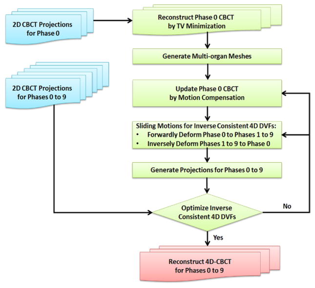
Figure 1 illustrates the flow chart of the proposed 4D-CBCT reconstruction method. Blue color boxes represent the input data; green color boxes represent the main algorithm part; the red color box represents the final output data. This paper focuses on: multi-organ mesh generation, modified SMEIR algorithm, inter-organ sliding motion modeling, and GPU-based parallel acceleration. These components are described in detail in the following sections.
Figure 1.
Flow chart of the proposed 4D-CBCT reconstruction method by multi-organ meshes for sliding motion modeling. Blue color boxes represent the input data; green color boxes represent the main algorithm part; the red color box represents the final output data.
2.1. Multi-organ mesh generation
In this section, we used a 4D NCAT phantom (Segars 2001) to demonstrate the detailed procedure of the multi-organ tetrahedral meshing.
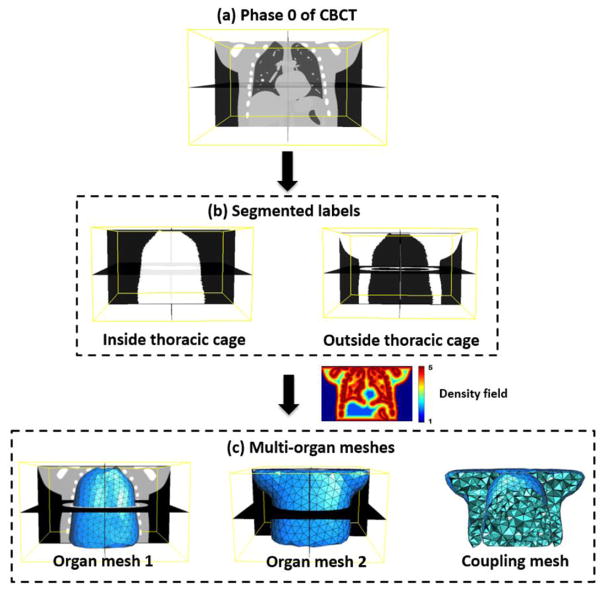
Firstly, an initial reference phase 0 of 4D-CBCT is reconstructed by TV minimization method (Wang and Gu 2013) from projections of phase 0. This reference image is then used to generate multi-organ meshes. ITK-SNAP (Yushkevich et al 2006) is used to segment the lung and thoracic cage parts (figure 2(b)) from reference phase 0 (figure 2(a)). In this study, the reference phase 4D-CBCT image is segmented into two parts as we mainly considered the discontinuity motion around the interface of the lung and thoracic cage for both 4D NCAT phantom and lung cancer patient. According to different requirements of the study, user can easily extend this two-organ segmentation into multi-organ cases. The binary images were created by setting ‘one’ inside the studied tissue and ‘zero’ on the outside. A multi-organ finite element modeling system was developed to automatically generate adaptive tetrahedral volume meshes (figure 2(c)) based on the segmented organ surfaces and image features.
Figure 2.
Demonstration of the multi-organ meshes generation on a digital 4D NCAT phantom. (a) The reference image at phase 0 of 4D-CBCT; (b) segmented label volumes; (c) multi-organ meshes well preserved the organ surfaces and image features.
The 3D adaptive volume meshing was generated according to the density field (as shown in figure 2) computed from the image features (i.e., searching for zero crossings in the second derivative of the image to find feature edges), which was extended from a particle-based adaptive surface meshing framework developed by Zhong et al (2013). This method is more efficient compared with other meshing methods (Shimada et al 1997, Du and Wang 2005, Valette et al 2008, Boissonnat et al 2015) as it only optimizes the vertex positions and finally computes the mesh connectivities once. Regarding each mesh vertex as a particle, the potential energy between particles determines the inter-particle forces. When the forces on each particle reach equilibrium, the particles are at an optimal balanced state, resulting in a uniform distribution in 3D space. In this case, the isotropic meshing can be generated. To generate the adaptive meshing, the concept of high-dimensional embedding space (Nash 1954, Kuiper 1955) was applied. When the forces applied on each particle reach an equilibrium state in this embedding space, the particle distribution on the original domain will exhibit the desired adaptive property, i.e., conforming to the user-defined density field. This property is used to formulate the particle-based adaptive meshing framework. As the tetrahedral mesh at each organ is computed based on the density field, more vertices (or sampling points) will be placed within feature areas, while fewer vertices will be in non-feature regions.
The inter-particle energy Ēij between particles i and j in the embedding space is defined as:
| (1) |
where vi and vj indicate the positions of particles i and j. Mij is the density field between particles i and j. It is a 3 × 3 diagonal matrix, and the main diagonal elements are density values. σ is Gaussian kernel width. It has been shown in (Zhong et al 2013) that the best adaptive mesh quality can be achieved when Gaussian kernel width is set as , where |Ω̄| is the image volume in the embedding space and Nv is the total number of particles. The gradient of Ēij can be considered as the inter-particle force F̄ij in the embedding space:
| (2) |
where . The details of the mathematical derivations are given in section 3.2.2 of reference (Zhong et al 2013).
The L-BFGS (Liu and Nocedal 1989) (a quasi-Newton algorithm) optimization method is used to obtain the optimized adaptive particle positions, with the inter-particle energy defined in equation (1) and force defined in equation (2), by minimizing the total inter-particle energy. During the optimization, the particles need to be constrained inside the organ volume. For each iteration, the updated particles need to be projected to their nearest locations on the organ surface, if they are out of the surface. The final adaptive tetrahedral mesh can be generated by using the Delaunay triangulation method (Berg et al 2008) according to the optimized particle positions for each organ.
2.2. Modified SMEIR algorithm
The original SMEIR algorithm consists of two alternating steps: a motion-compensated image reconstruction and a motion model estimation. After mesh generation, a modified simultaneous algebraic reconstruction technique (mSART) (Wang and Gu 2013) is used to perform motion-compensated reconstruction for the reference phase of 4D-CBCT by using projections from all phases. Let T denote the total phases in a 4D-CBCT, P = {pt|t = 0,..., T − 1} and denote the projections for all phases; and μ = {μt|t = 0,...,T − 1} and denote attenuation coefficients for all phases; the voxel value at index j of phase 0 in the mSART algorithm is updated iteratively as:
| (3) |
| (4) |
where k is the iterative step, and λ is the relaxation factor which is set as 1.0 in our experiments (Wang and Gu 2013). is the element of the projection matrix, denoting the intersection length of projection ray i with voxel n at phase t which is calculated by the fast ray-tracing technique (Han et al 1999). Equation (4) describes the forward deformation that transforms 4D-CBCT from phase 0 to phase t where n is voxel index at phase t. In equation (4), denotes the element of the deformation matrix D0→t specified at voxels of the image, which can be interpolated from the DVF specified at mesh vertices W as follows:
| (5) |
where INT denotes the interpolation calculation by using the barycentric coordinates (Coxeter 1969) of each voxel in its corresponding tetrahedron. It is noted that the number of the tetrahedrons is far less than the number of the voxels and the density field guarantees that the smallest tetrahedron has more than one voxels. In equation (3), the second term defines the inverse deformation that transforms the error image determined by projections at phase t to update the 4D-CBCT at phase 0. denotes the element of the inverse deformation matrix Dt → 0. After mSART reconstruction, the TV of the reconstructed m-pCBCT is minimized by the standard steepest descent method (Wang and Gu 2013) to suppress the noise.
In the motion model estimation step, the updated motion model of multi-organ mesh W is obtained by matching the 4D-CBCT projections at each phase with the corresponding forward projections of the deformed m-pCBCT. From equations (3) and (4), both the forward and inverse DVFs are needed for updating μ0. Thus inverse consistent DVF is required. To enforce the inverse consistency of the DVF, a symmetric energy function under an inverse consistent constraint is computed to optimize the DVF. The symmetric energies E1 and E2 include two terms: the data fidelity term Efid between the projections of two phases and the regularization term Ereg to achieve smoothness of DVF:
| (6) |
The data fidelity is defined as:
| (7) |
where A is the projection matrix with element ai,n. x is the voxels’ positions before deformation.
The regularization term consists of two parts as follows:
| (8) |
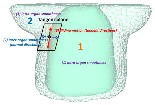
where L(W) is the smoothness constraint of intra-organ motion, which encourages the smoothness of W inside each organ. S(W) is the inter-organ motion constraint that encourages the motion smoothness along the normal directions of the organ surfaces and allows the sliding motion between the interface of organs along the tangential directions of the organ surfaces. These constraints are graphically illustrated in figure 3. α, β are parameters that control the tradeoff between data fidelity and smoothness constraints of the DVF. The parameters α, β are empirically set at 10.0, 1.0 for all of the studies on the phantom and patient data in this paper.
Figure 3.
Three different constraints between and inside the organs: intra-organ smoothness, inter-organ smoothness, and sliding motion.
The total energy function considering all T phases is:
| (9) |
where W = {w0→t ∪ wt→0|t = 0,...,T − 1}. The L-BFGS optimization method is used to minimize E and obtain the optimized DVF W. For each iteration of L-BFGS optimization, the energy E and its gradient are updated.
2.3. Intra-organ smoothness constraint
The intra-organ constraint encourages the smoothness of the DVF within each organ, due to the motion consistency. L(W) is computed over every vertex of the organ mesh:
| (10) |
where L(W) is a summation of the square of Graph Laplacian operations (Zhou et al 2005) on the DVF (including three components: d = 1, 2, 3) over all vertices of one organ mesh. Nv is the number of vertices of each tetrahedral organ mesh. N(a) is the set of one-ring connected neighboring vertices (b) of vertex a in each organ. |N(a)| is the size of set N(a). The total intraorgan smoothness constraint is the result of the sum of all the intra-organ constraints from the meshes.
2.4. Inter-organ motion constraint
Conventional regularizers typically enforce global smoothness, leading to inaccurate motion estimation near the discontinuous locations, such as the interfaces between organs moving independently from one another. During respiration, the lungs, abdominal organs, and the thoracic cage exhibit sliding motions between their interfaces. In lungs, sliding occurs between the visceral and parietal pleural membranes that form the pleural sacs surrounding each lung (Agostoni and Zocchi 1998, Wang 1998, Vandemeulebroucke et al 2012). In the abdomen region, a prominent sliding interface is present at the peritoneal cavity between the abdominal cavity and the abdominal wall (Tortora and Derrickson 2008). The globally smoothing regularizations would underestimate motion near the sliding boundaries by averaging possible opposite motions. The motion for each organ may not be correctly estimated without introducing additional degrees of freedom at sliding borders.
Our proposed multi-organ adaptive meshing framework can provide an effective solution to this sliding motion problem. This method can accurately represent surface shapes and smoothness, leading to improved modeling of the deformations around the organ interfaces. The motions between organs are grouped into two categories: (1) continuous motion along the normal direction, and (2) discontinuous motion along the tangential direction of the organ surface.
-
Inter-organ smoothness occurs in the normal directions of the organ surfaces, and is continuous, even they belong to different organs. S(wvsurface) is the sliding regularization term defined in the normal directions of the organ surface DVFs (w⊥) as follows:
(11) where Nvsurface is the number of boundary vertices of each tetrahedral organ mesh. N(m) is the set of K nearest neighboring vertices (n) of vertex m. Euclidean distance is used to determine the neighbors. |N(m)| is the size of set N(m). The total inter-organ smoothness constraint is the sum of all the inter-organ constraints of meshes.
-
Sliding motion occurs in the tangential directions of the organ surfaces, and is discontinuous between different organs, despite their vicinity to one another. Since the DVFs for organ interfaces are constrained on the organ surface C, the gradients need to be constrained within the tangent space of C during minimizing the total energy. Thus we have:
(12) where wvsurface are the DVFs specified on boundary vertices of organ meshes.
2.5. GPU-based parallel acceleration
The entire process of the proposed 4D-CBCT reconstruction method was fully implemented on GPU. The GPU card used in our experiments is a NVIDIA Tesla K40c with 12GB GDDR5 video memory. The card has 2880 CUDA cores with tremendous parallel computing ability that can substantially increase the computational efficiency. There were three time-consuming processes during the reconstruction. The first was the motion compensated image reconstruction; the second was the projection generation in the total energy computation, and the third was the gradient computation of the total energy during the motion estimation step. For projection computation, the ray tracing algorithm in parallel computation was easy to accomplish. For example, the intensity of each pixel within the projection was determined by accumulating all of the weighted voxel intensities through which one ray goes, i.e., integral of the intersection lengths of one projection ray going through voxels. This computation process completely depends on individual ray line. In this case, different GPU threads could compute each ray line simultaneously without conflict. Furthermore, because the projections at different phases can be all independently computed at the same time, the computation is parallelly calculated on GPU. The gradient computation of the total energy w.r.t. DVFs is parallelly computed on GPU as well. The detailed timing information of experiments in this paper is given in section 3.4.
2.6. Synthetic sliding motion phantom
A 3D synthetic phantom was first used to test the proposed multi-organ mesh-based image reconstruction algorithm. In this study, there were two sets of 3D images, representing the same phantom at two different moving phases. In figure 4, the left panel shows the 3D image before sliding, while the right panel shows the image after sliding. To demonstrate the robustness of the proposed method, we simulated an extreme case of the sliding motion in the moving image. The scenario was as follows: the intensities of two 3D boxes were linearly increasing from left to right and the upper box had higher intensity values than those of the lower box. After sliding, the upper box was translated with 50 mm to the right side, and the lower box was translated with 50 mm to the left side. The dimensions of the phantom were 256 × 256 × 132 with voxel size of 2 mm × 2 mm × 2 mm. Projections were generated by using a ray-tracing algorithm. The dimensions of each projection after sliding were 300 × 240 with detector pixel size of 2 mm × 2 mm. Twenty projections with noise (Wang et al 2006) were simulated and evenly distributed over 360°.
Figure 4.
3D synthetic sliding motion phantom.
2.7. 4D NCAT digital phantom
In this study, ten breathing phases of the 4D NCAT phantom were generated with a breathing period of 4 s. The maximum diaphragm motion was 20 mm and the maximum chest anterior–posterior motion was 12 mm during the respiration. A spherical 3D tumor with diameter of 10 mm was also simulated as shown in Row 1 of figure 8. The dimensions of the phantom were 256 × 256 × 150 with voxel size of 2 mm × 2 mm × 2 mm. Projections of ten phases of 4D-CBCT were generated by using a ray-tracing algorithm. The dimensions of each projection were 300 × 200 with detector pixel size of 2 mm × 2 mm. Twenty projections with noise (Wang et al 2006) were simulated for each phase of 4D-CBCT and were evenly distributed over 360°.
Figure 8.
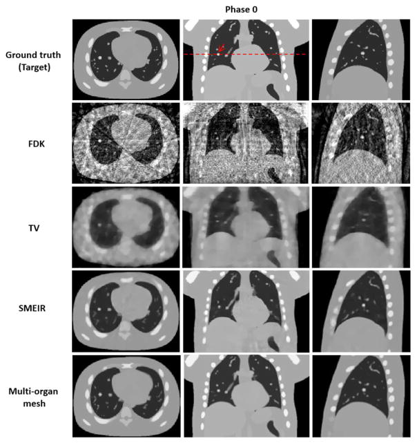
Reconstructed 4D NCAT phantom at phase 0 (end-expiration) by using 4 different reconstruction algorithms with average projection numbers of 20. FDK: Feldkamp–Davis–Kress; TV: total variation. SMEIR: simultaneous motion estimation and image reconstruction. First through third columns show the transaxial, coronal, and sagittal views, respectively. Display window for all images is [0, 0.05] mm−1.
2.8. Lung cancer patient data
Finally, a clinical evaluation study was performed on four lung cancer patients. Data acquisitions on these patients were under an institutional review board protocol (ID00-202). The patients were scanned with a Trilogy system (Varian Medical System, Palo Alto, CA), with 120 kV, 80 mA, and 25 ms pulsed x-ray. A full fan bowtie filter was used, and projections were acquired with a 200° range. The scan field of view was 26.5 cm in diameter, and the cranial–caudal coverage was 15 cm. To get a reference 4D-CBCT at each phase, the patient underwent 4 to 6 min of scanning with a slow gantry rotation to acquire 1982, 1679, 2005, and 2730 projections, respectively. With this large number of projections, high-quality 4D-CBCTs were obtained and used as references in our evaluation study. A real-time position management (RPM) system was used to acquire the respiratory signals. The acquired projections were sorted into 10 respiration phases according to the recorded RPM signal. From each fully sampled projection phase (such as acquired in 4 min), a downsampling factor of 8 was used to decrease the projection within each phase. The projection degree range is still 200° in each phase. The average projection numbers per phase were about 30 to 40 after the downsampling. These downsampled projections were subsequently used for reconstructions by FDK, TV, single and multi-organ meshing methods. The 4D-CBCT reconstructed by TV minimization from the fully sampled projections was used as a reference for the following comparison study. The image reconstruction accuracy of 4D-CBCT from different reconstruction schemes was quantified by comparing them to the corresponding reference 4D-CBCT. The dimensions of reconstructed images were 200 × 200 × 100 with voxel size of 2 mm × 2 mm × 2 mm.
2.9. Evaluations
A conventional normalized cross correlation (NCC) was used to evaluate the similarity between the reconstructed image and target image:
| (13) |
where Frecon(i) and F(i) are the reconstructed and target values, respectively, over N voxels. F̄recon and F̄ are the average values of the reconstructed and target values.
The normalized root mean square error (NRMSE) between the reconstructed values Frecon(i) and the target values F(i) was also used to calculate reconstruction error:
| (14) |
It is noted that a larger NCC or a smaller NRMSE indicate that the reconstructed image is more similar to the ground truth image.
3. Results
3.1. Results of synthetic sliding motion phantom
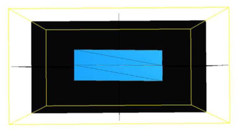
Tetrahedral meshes were created in both upper and lower boxes with 8 vertices respectively, as shown in figure 5. Since the intensities of two 3D boxes linearly increase from left to right, there is no feature inside each box image. Therefore, two tetrahedral meshes are sufficient to control the sliding motion in this example.
Figure 5.
Meshes of synthetic sliding motion phantom.
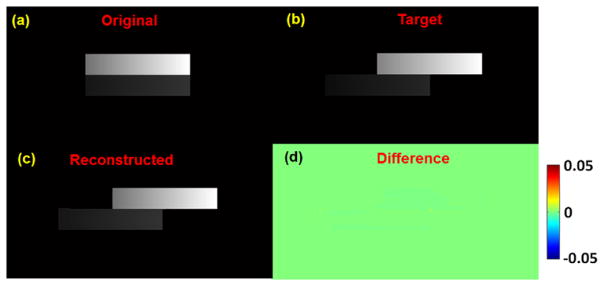
Figure 6 shows the reconstruction result of synthetic sliding motion phantom in coronal view. Figure 6(a) is the original image before sliding and figure 6(b) is the target image after sliding both upper and lower boxes by 50 mm in opposite directions. Figure 6(c) shows that the reconstructed image by using the proposed method with considering the inverse consistency of DVF, is very close to the target image. Their differences are very small, as illustrated in figure 6(d). For quantitative evaluations, in the final 3D reconstructed image, NCC is 0.999 and NRMSE is 0.04.
Figure 6.
The reconstruction result of synthetic sliding motion phantom in coronal view. (a) Original image (before sliding); (b) target image (after sliding); (c) reconstructed image from the original image; (d) differences between reconstructed and target images. Display window for (a)–(c) is [0, 0.05] mm−1.
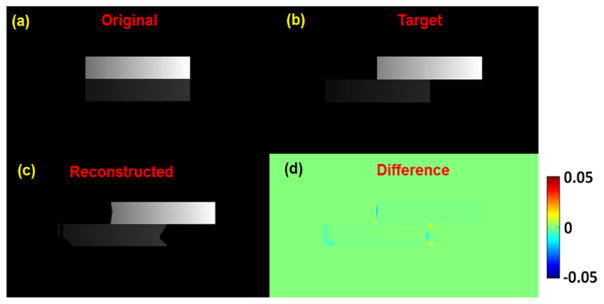
Figure 7 shows the results without considering the inverse consistency of DVFs, i.e., optimize two sets of transformations, the forward and inverse DVFs independently during the motion estimation step. The boxes in the final image cannot be well deformed and matched due to the large sliding motion, especially at the ends of the boxes. In the final reconstructed image, NCC is 0.997 and NRMSE is 0.07. These results demonstrate that the inverse consistency of DVF is necessary in the reconstruction process.
Figure 7.
The reconstruction without inverse consistency of DVF result of synthetic sliding motion phantom in coronal view. (a) Original image (before sliding); (b) target image (after sliding); (c) reconstructed image from the original image; (d) differences between reconstructed and target images. Display window for (a)–(c) is [0, 0.05] mm−1.
3.2. Results of 4D NCAT digital phantom
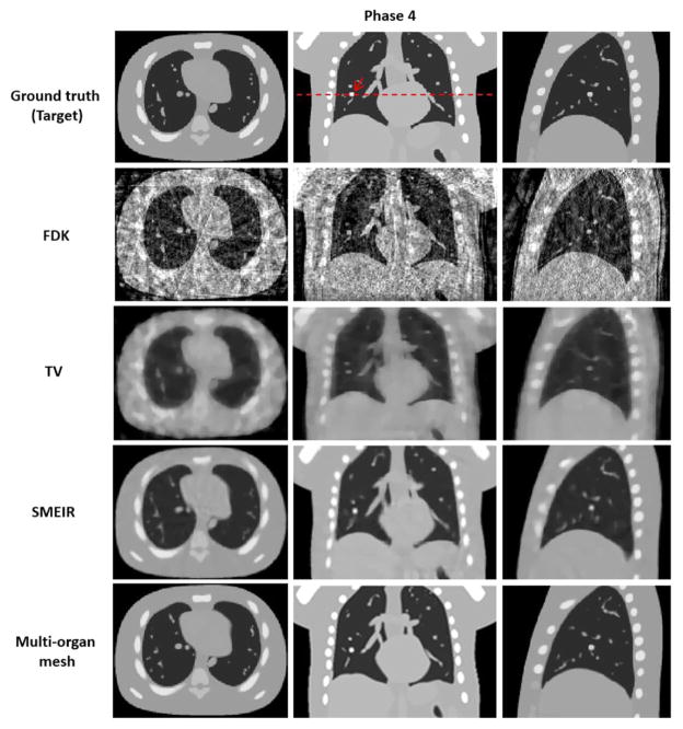
Both lung and thoracic cage tetrahedral meshes were created with about 1000 vertices respectively from the reference phase 0 of 4D-CBCT as shown in figure 2. Figures 8 and 9 show images of the 4D NCAT phantom at the end-expiration (phase 0) and end-inspiration (phase 4) phases from transaxial, coronal, and sagittal views, respectively, with four different reconstruction methods. Row 1 in figures 8 and 9 shows the digital phantom images at phases 0 and 4, which were used as ground truth images for the evaluation. Row 2 in figures 8 and 9 shows 4D-CBCT reconstructed by the FDK algorithm (Feldkamp et al 1984), and severe view aliasing artifacts are presented. Row 3 in figures 8 and 9 shows 4D-CBCT reconstructed by TV minimization (Song et al 2007, Solberg et al 2010). Bony structures and fine structures inside the lung, such as the tumor, are over blurred although view aliasing artifacts are suppressed. Row 4 in figures 8 and 9 shows 4D-CBCT reconstructed by the original SMEIR method (Wang and Gu 2013). The image details are maintained for both bony and fine structures including the tumor, but the organ boundaries are slightly blurred. Row 5 in figures 8 and 9 shows images reconstructed by the multi-organ meshing method. The image details are well preserved for bony, tumor, and other fine structures without aliasing artifacts.
Figure 9.
Reconstructed 4D NCAT phantom at phase 4 (end-inspiration) by using 4 different reconstruction algorithms with average projection numbers of 20. FDK: Feldkamp–Davis–Kress; TV: total variation. SMEIR: simultaneous motion estimation and image reconstruction. First through third columns show the transaxial, coronal, and sagittal views, respectively. Display window for all images is [0, 0.05] mm−1.
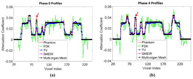
Figures 10(a) and (b) show the horizontal profiles through the tumor center of coronal view images to further illustrate the performance of different image reconstruction strategies at phase 0 and phase 4. The profile from the proposed multi-organ mesh method is very close to the phantom ground truth. Table 1 reports the quantitative evaluations on the 4D NCAT phantom.
Figure 10.
Horizontal profiles through the center of coronal view images at (a) phase 0 and (b) phase 4. The arrow indicates the tumor position.
Table 1.
Evaluation of reconstruction accuracy on a 4D NCAT phantom.
| Method | FDK | TV | SMEIR | Multi-organ mesh | |
|---|---|---|---|---|---|
| NCC | Phase 0 | 0.865 | 0.982 | 0.988 | 0.998 |
| Phase 4 | 0.862 | 0.982 | 0.987 | 0.992 | |
| NRMSE | Phase 0 | 0.462 | 0.162 | 0.131 | 0.055 |
| Phase 4 | 0.467 | 0.162 | 0.134 | 0.084 |
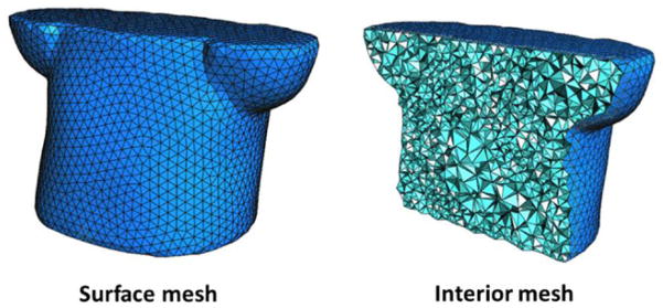
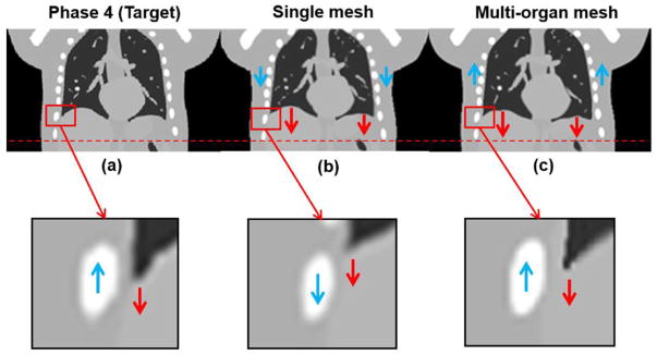
To further demonstrate the advantage of the proposed multi-organ meshing method, we also reconstructed the NCAT phantom using a single adaptive mesh, i.e., an adaptive tetrahedral mesh based on image features (density field as shown in figure 2) for the entire body without considering organ segmentations (figure 11). Figure 12(a) is the ground truth image at phase 4; (b) shows the reconstructed image by the single mesh method; (c) shows the reconstructed image result by the proposed multi-organ mesh method. From phase 0 (column 2 of figure 8) to phase 4 (column 2 of figure 9), it can be observed that the tissues and tumor inside the lung are moving downward, while the thoracic cage is moving upward. If we used a single mesh model as shown in figure 12(b), the motions inside the thorax, such as in the lung, the tumor, and the diaphragm, could be well-captured, while the motion of the thoracic cage could not. The smoothness of motion fields cross the interface of organs discourages the discontinuity in the motion fields (i.e., sliding motion) along the tangential direction of the thorax interface.
Figure 11.
Single mesh model of 4D NCAT phantom.
Figure 12.
Demonstration of 4D NCAT at phase 4 results at coronal views. (a) Target image (phase 4); (b) reconstructed image by the single mesh method; (c) reconstructed image by the proposed multi-organ mesh method. Display window for (a)–(c) is [0, 0.05] mm−1.
When the multi-organ mesh model was used, the boundary of the lung and thoracic cage was well-preserved, so that the motions of interface were more accurate, as shown in figure 12(c). As for quantitative evaluations, NCCs between reconstructed image and the ground truth image for single mesh and multi-organ mesh-based methods were 0.989 and 0.992, respectively; the maximum motion errors along the interface between the lung and thoracic cage for the single and multi-organ mesh-based methods were 6.12 mm, and 0.95 mm, respectively. Through this phantom example, we can expect that if the tumor is located around the interface between the lung and the thoracic cage, both the image visualization accuracy and motion estimation will be brought down.
3.3. Results of lung cancer patient data
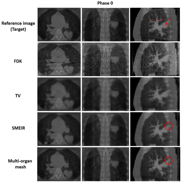
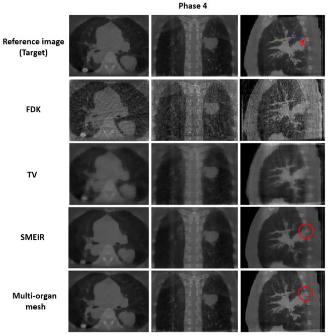
Similarly to the 4D NCAT phantom experiment, adaptive tetrahedral meshes (figure 13) were created with about 1000 vertices for both the lung and thoracic cage, respectively from the reference phase 0 of 4D-CBCT lung cancer patient data. In order to demonstrate the significance of the proposed method for accurate visualization and motion estimation with tumor in 4D-CBCT, we specifically choose a lung cancer patient data with tumor located around the interface between the lung and the thoracic cage. Figures 14 and 15 show images of the lung cancer patient 1 data with tumor as indicated by the arrow at the end-inspiration (phase 0) and end-expiration (phase 4) phases from transaxial, coronal, and sagittal views, respectively, with four different reconstruction methods. Row 1 in figures 14 and 15 shows the TV minimization from the fully sampled projections with average projection numbers of 200 per phase. The projections are considered as ground truth images for evaluation. Row 2 in figures 14 and 15 shows 4D-CBCT reconstructed by the FDK algorithm, and severe noise and artifacts are presented due to the limited number of projections at each phase. Row 3 in figures 14 and 15 shows 4D-CBCT reconstructed by TV minimization, and bony structures and fine structures within the lung, such as the tumor, are over smoothed although view aliasing artifacts are suppressed. Row 4 in figures 14 and 15 shows images reconstructed by SMEIR method. Bony and fine structures inside the lung are preserved but the organ boundaries are slightly oversmoothed, especially for the tumor and thoracic cage boundary (indicated by the red circle). Row 5 in figures 14 and 15 shows images reconstructed by the multi-organ meshing method. Bony and fine structures, especially the tumor inside the lung are well preserved without aliasing artifacts.
Figure 13.
Multi-organ meshes of lung cancer patient data.
Figure 14.
Reconstructed lung cancer patient 1 at phase 0 (end-inspiration) by using 4 different reconstruction algorithms with average projection numbers of 38. FDK: Feldkamp–Davis–Kress; TV: total variation. SMEIR: simultaneous motion estimation and image reconstruction. First through third columns show the transaxial, coronal, and sagittal views, respectively. Display window for all images is [0, 0.12] mm−1.
Figure 15.
Reconstructed lung cancer patient 1 at phase 4 (end-expiration) by using 4 different reconstruction algorithms with average projection numbers of 38. FDK: Feldkamp–Davis–Kress; TV: total variation. SMEIR: simultaneous motion estimation and image reconstruction. First through third columns show the transaxial, coronal, and sagittal views, respectively. Display window for all images is [0, 0.12] mm−1.
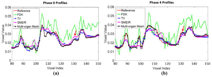
Figures 16(a) and (b) show the horizontal profiles through the bony and fine structures inside the lung to further illustrate the difference between different reconstruction methods at phase 0 and phase 4 of lung cancer patient 1 data at sagittal views. Table 2 reports the quantitative evaluations on the lung cancer patient 1. Figure 17 shows the reconstructed phase 4 (end-expiration) image results of the single mesh and multi-organ mesh methods. The sliding motion between the thoracic cage and lung can be well preserved by using the multi-organ mesh method (figure 17(c)), especially for the tumor that is close to the lung boundary indicated by the arrow. While in the result of the single mesh method, the tumor motion is moving downward (figure 17(b)), and it is affected by the thoracic cage motion during expiration. The front edge of the tumor region were calculated to measure the tumor motion along the z-axis. The maximum motion errors of the tumor for the single and multi-organ mesh-based methods were 3.26 mm, and 0.51 mm, respectively.
Figure 16.
Horizontal profiles through the center of sagittal view images at (a) phase 0 and (b) phase 4 of lung cancer patient 1. The arrow indicates the tumor boundary close to the bone.
Table 2.
Evaluation of reconstruction accuracy on lung cancer patient 1.
| Method | FDK | TV | SMEIR | Multi-organ mesh | |
|---|---|---|---|---|---|
| NCC | Phase 0 | 0.541 | 0.929 | 0.936 | 0.948 |
| Phase 4 | 0.544 | 0.927 | 0.931 | 0.947 | |
| NRMSE | Phase 0 | 0.836 | 0.262 | 0.242 | 0.223 |
| Phase 4 | 0.835 | 0.263 | 0.245 | 0.226 |
Figure 17.
Demonstration of lung cancer patient 1 at phase 4 results at sagittal views. (a) Target image (phase 4); (b) reconstructed image by the single mesh method; (c) reconstructed image by the proposed multi-organ mesh method. Display window for (a)–(c) is [0, 0.12] mm−1.
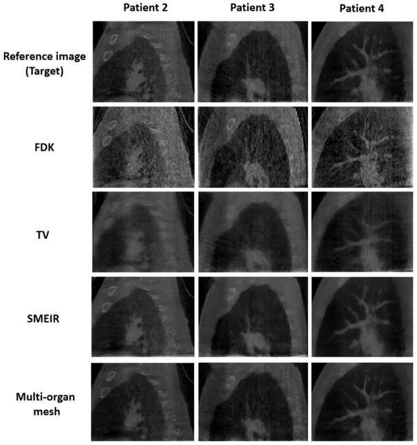
In order to show the robustness and effectiveness of our proposed method, we further evaluated on three more lung cancer patients. Figure 18 and table 3 show the reconstructed images and quantitative evaluations of patient 2–4 at phase 0 with average projection numbers of 33, 33, and 38, respectively. The results show that the proposed multi-organ mesh algorithm produces 4D-CBCT images that are closest to the reference image among the 4 reconstruction methods investigated in this study. It is clear to see that the proposed reconstruction preserves fine structures and organ boundaries very well without aliasing artifacts, and has highest accuracy based on quantitative measurements.
Figure 18.
Reconstructed lung cancer patient 2–4 at phase 0 (end-inspiration) at sagittal views by using 4 different reconstruction algorithms. FDK: Feldkamp–Davis–Kress; TV: total variation. SMEIR: simultaneous motion estimation and image reconstruction. First through third columns show patient 2, patient 3, and patient 4, respectively. Display window for all images is [0, 0.12] mm−1.
Table 3.
Evaluation of reconstruction accuracy on lung cancer patient 2–4 at phase 0.
| Method
|
FDK
|
TV
|
SMEIR
|
Multi-organ mesh
|
||||
|---|---|---|---|---|---|---|---|---|
| Data | NCC | NRMSE | NCC | NRMSE | NCC | NRMSE | NCC | NRMSE |
| Patient 2 | 0.741 | 0.795 | 0.915 | 0.292 | 0.930 | 0.253 | 0.937 | 0.242 |
| Patient 3 | 0.726 | 0.809 | 0.870 | 0.408 | 0.914 | 0.306 | 0.927 | 0.286 |
| Patient 4 | 0.720 | 0.984 | 0.926 | 0.268 | 0.937 | 0.225 | 0.955 | 0.220 |
3.4. Computational time
Table 4 shows the timing information in each step per iteration during the reconstruction in the proposed GPU-based 4D-CBCT reconstruction method and the original CPU-based SMEIR method. It is noted that the mesh generation step does not show in the table, since it only needs to be computed once before motion compensated image reconstruction and DVF optimization. In the 4D NCAT phantom and lung cancer patient data, it needs 30 s for the mesh generation (i.e., 2000 vertices of multi-organ adaptive tetrahedral meshes). The optimization totally needs to be run with 10 iterations of motion compensation and 30 iterations of DVF estimation. The overall computational time of reconstruction of a 4D 200 × 200 × 100 patient image with 10 phases is 245.7 s (4.10 m); however, the CPU-based SMEIR method needs more iterations, and the computational time is about 15 h. There are two main reasons for the speedup of reconstruction: (1) the original SMEIR method is designed and implemented by sequential computations on CPU, while our proposed method is based GPU parallel computation and implementation; (2) the number of unknowns in the original SMEIR method is equal to the number of total voxels (i.e., about 2003), which is very huge and much larger than the unknowns in the proposed mesh-based method, i.e., the number of mesh vertices (i.e., about 2000). During DVF optimization, it has slower convergence rate (more iterations) and the computational time of each iteration is much longer as well. Therefore, the proposed method has dramatically improved the running speed and makes it possible to reach our ultimate target to develop a less-than-1 min system for its clinical applications in the near future.
Table 4.
Timing information of one iteration for all steps during the reconstruction.
| Step | Time (s)
|
||||
|---|---|---|---|---|---|
| 4D NCAT
|
Patient
|
||||
| SMEIR | Proposed method | SMEIR | Proposed method | ||
| (1) Motion compensation | 231.48 | 14.43 | 90.51 | 5.67 | |
| (2) DVF estimation | (2.1) Total energy computation | 416.75 | 3.40 | 196.33 | 2.06 |
| (2.2) Gradient of total energy computation | 10.23 | 4.24 | |||
4. Discussion and conclusion
The proposed 4D-CBCT reconstruction method used the multi-organ mesh model for estimating organ motions and demonstrated better image results compared with previous reconstruction approaches, such as FDK, TV minimization, SMEIR, and single mesh method. The main feature of the proposed framework is to construct multi-organ meshes according to the structures of organs and tissues. A heterogeneous multi-organ meshing model was built to capture the structures and motions of different organs more accurately than that of a single mesh model. The sliding motions between organ interfaces were considered, so that the oversmoothness of motion fields across the organ boundaries in the global regularization model could be avoided. Especially, our proposed method can improve the visualization and motion estimation accuracy of the tumor on the organ boundaries in 4D-CBCT. Furthermore, improving motion estimation accuracy is also important for future applications of 4D-CBCT such as dose reconstruction for adaptive radiation therapy. While the on-board CBCT provides accurate dose reconstruction for static sites, motion artifact is a dominant factor that degrades the dose reconstruction accuracy (Yang et al 2007). With accurate deformation vector fields, dose distribution from individual phase can be mapped to a reference phase 4D-CBCT. Therefore, improving motion estimation accuracy at organ interface is of significance even if the tumor is not around the lung boundary. While we termed our developed method ‘multi-organ’ mesh model, we essentially construct a two-organ mesh model in this work since we only focused on the sliding motion between lung and thoracic cage. However, the proposed method can be readily applied to other applications if more than two organ boundaries need to be considered.
It is noted that the original 4–6 min scans were performed with a slow gantry rotation that covered a 200° range. By selecting 1 out of every 8 projections during our downsampling procedure, we essentially simulated that the downsampled projections were acquired with a slower acquisition frame rate. These downsampled projections were still over 4–6 min to cover a 200° scan range. Since 4–6 min spans much more number of respiration cycles than 1 min, these undersampled projections do not truly represent a ‘within’ 1 min scan acquired with a standard acquisition frame rate. Therefore, the results obtained in the clinical patient study cannot be directly interpolated as 1 min scan with the standard acquisition frame rate. To evaluate the performance on 1 min 4D-CBCT, one would need patient data with a 1 min scan time with the standard acquisition frame rate and a long time acquisition scan such as the data used in this study. However, this clinical evaluation study is beyond the scope of this work and future studies are warranted.
Other than the proposed multi-organ meshing method, the voxel domain based motion fields regularization could also be used to model the sliding motion. Pace et al (2013) recently proposed a deformable image registration (DIR) algorithm that uses anisotropic smoothing for regularization to find correspondences between images of sliding organs via the voxel-based model. Nevertheless, in the voxel-based representation, it is challenging to obtain accurate tangential and normal directions of the organ surfaces, because the computation is based on the voxel-based non-smooth and jagged surface, and this geometric surface information is unreliable. Conversely, the mesh-based model can obtain more accurate tangential and normal directions of the organ surfaces due to its intrinsic smoothness within and around each element (Chen and Schmitt 1992). Favorable properties of the mesh enable us to efficiently and accurately estimate the motions between and inside the organs.
Mesh-based representation has been previously explored for emission tomographic image reconstruction. Instead of updating the voxel values during the reconstruction process, such a strategy only estimates the nodal values in a content adaptive mesh model. Different from previous applications of mesh for image reconstruction (Brankov et al 2002, 2004), the mesh model in this work is used only to improve the motion estimation accuracy. In the motion-compensated image reconstruction in this work, the updating is still performed on voxels of the image. As the mesh has been generated for motion estimation, we could also update the nodal values of the mesh during the reconstruction similar to the strategy described in (Brankov et al 2002, 2004). However, the image resolution of transmission tomographic imaging (e.g. CBCT) is much higher than that of the emission tomographic imaging. Thus mesh of higher resolution is also required for CBCT representation. A future study is warranted to investigate whether mesh-based representation can outperform voxel-based reconstruction for CBCT.
In addition to considering the spatial motion constraints, temporal motion constraints could also be incorporated into the 4D-CBCT image reconstruction. In the future work, we will consider the inter-phase motion constraints to enforce motion smoothness between neighboring phases during 4D-CBCT image reconstruction. This could lead to further improvement on motion estimation accuracy at a cost of additional computation.
With the help of a single GPU-based implementation, the computational speed of the original SMEIR algorithm has been greatly improved. For the 4D lung cancer patient data presented in this work, it can be reconstructed around 4 min. Nevertheless, the proposed 4D-CBCT reconstruction scheme can be further sped up. We can specifically implement the 4D multi-organ mesh-based image reconstruction on a GPU cluster, where the DVF estimation for each phase can be computed independently on different GPU cards. By using a GPU cluster, we aim to make the developed less-than-1 min system suitable for routine clinical use.
Acknowledgments
We acknowledge funding support from the American Cancer Society (RSG-13-326-01-CCE), US National Institutes of Health (R01 EB020366) and Elekta Ltd. We would like to thank Dr Damiana Chiavolini for editing the paper. We thank Dr Tinsu Pan from University of Texas MD Anderson Cancer Center for sharing patient datasets in the evaluation study. We would also like to thank the anonymous reviewers for their constructive comments and suggestions that greatly improved the quality of the paper.
References
- Agostoni E, Zocchi L. Mechanical coupling and liquid exchanges in the pleural space. Clin Chest Med. 1998;19:241–60. doi: 10.1016/s0272-5231(05)70075-7. [DOI] [PubMed] [Google Scholar]
- Ahn B, Kim J. Measurement and characterization of soft tissue behavior with surface deformation and force response under large deformations. Med Image Anal. 2010;14:138–48. doi: 10.1016/j.media.2009.10.006. [DOI] [PubMed] [Google Scholar]
- Berg MD, Cheong O, Kreveld MV, Overmars M. Computational Geometry: Algorithms and Applications. Berlin: Springer; 2008. [Google Scholar]
- Bergner F, Berkus T, Oelhafen M, Kunz P, Pa T, Grimmer R, Ritschl L, Kachelriess M. An investigation of 4D cone-beam CT algorithms for slowly rotating scanners. Med Phys. 2010;37:5044–53. doi: 10.1118/1.3480986. [DOI] [PubMed] [Google Scholar]
- Bergner F, Berkus T, Oelhafen M, Kunz P, Pan T, Kachelriess M. Autoadaptive phase-correlated (AAPC) reconstruction for 4D CBCT. Med Phys. 2009;36:5695–706. doi: 10.1118/1.3260919. [DOI] [PMC free article] [PubMed] [Google Scholar]
- Boissonnat JD, Shi KL, Tournois J, Yvinec M. Anisotropic delaunay meshes of surfaces. ACM Trans Graph. 2015;34:1–11. [Google Scholar]
- Brankov JG, Yang YY, Wernick MN. Content-adaptive 3D mesh modeling for representation of volumetric images. Proc. 2002 Int. Conf. on Image Process; 2002. pp. 849–52. [Google Scholar]
- Brankov JG, Yang YY, Wernick MN. Tomographic image reconstruction based on a content-adaptive mesh model. IEEE Trans Med Imag. 2004;23:202–12. doi: 10.1109/TMI.2003.822822. [DOI] [PubMed] [Google Scholar]
- Chen X, Schmitt F. Intrinsic surface properties from surface triangulation. Proc. 2nd European Conf. on Computer Vision; 1992. pp. 739–43. [Google Scholar]
- Chen G-H, Tang J, Leng S. Prior image constrained compressed sensing (PICCS): a method to accurately reconstruct dynamic CT images from highly undersampled projection data sets. Med Phys. 2008;35:660–3. doi: 10.1118/1.2836423. [DOI] [PMC free article] [PubMed] [Google Scholar]
- Clatz O, Delingette H, Talos I, Golby A, Kikinis R, Jolesz F, Ayache N, Warfield S. Robust nonrigid registration to capture brain shift from intraoperative MRI. IEEE Trans Med Imag. 2005;24:1417–27. doi: 10.1109/TMI.2005.856734. [DOI] [PMC free article] [PubMed] [Google Scholar]
- Coxeter H. Introduction to Geometry. New York: Wiley; 1969. pp. 216–21. [Google Scholar]
- Dang J, Gu XJ, Pan TS, Wang J. A pilot evaluation of a 4-dimensional cone-beam computed tomographic scheme based on simultaneous motion estimation and image reconstruction. Int J Radiat Oncol Biol Phys. 2015;91:410–8. doi: 10.1016/j.ijrobp.2014.10.029. [DOI] [PubMed] [Google Scholar]
- Du Q, Wang D. Anisotropic centroidal Voronoi tessellations and their applications. SIAM J Sci Comput. 2005;26:737–61. [Google Scholar]
- Feldkamp LA, Davis LC, Kress JW. Practical cone-beam algorithm. J Opt Soc Am A. 1984;1:612–9. [Google Scholar]
- Ferrant M, Warfield S, Nabavi A, Jolesz F, Kikinis R. Medical Image Computing and Computer-Assisted Intervention (MICCAI) 2000. Registration of 3D intraoperative MR images of the brain using a finite element biomechanical model; pp. 19–28. [Google Scholar]
- Fogtmann M, Larsen R. Adaptive mesh generation for image registration and segmentation. 20th IEEE Int. Conf. on Image Processing (ICIP).2013. [Google Scholar]
- Foteinos P, Liu Y, Chernikov A, Chrisochoides N. Computational Biomechanics for Medicine. Berlin: Springer; 2011. An evaluation of tetrahedral mesh generation for nonrigid registration of brain MRI; pp. 131–42. [Google Scholar]
- Haber E, Heldmann S, Modersitzki J. Adaptive mesh refinement for nonparametric image registration. J SIAM J Sci Comput. 2008;30:3012–27. [Google Scholar]
- Han G, Liang Z, You J. A fast ray-tracing technique for TCT and ECT studies. IEEE Nucl Sci Symp Conf Rec. 1999;3:1515–8. [Google Scholar]
- Hu Y, Carter TJ, Ahmed HU, Emberton M, Allen C, Hawkes DJ, Barratt DC. Modelling prostate motion for data fusion during image-guided interventions. IEEE Trans Med Imag. 2011;30:1887–900. doi: 10.1109/TMI.2011.2158235. [DOI] [PubMed] [Google Scholar]
- Kuiper NH. On C1-isometric embeddings I. Proc Nederl Akad Wetensch Ser A. 1955;58:545–56. [Google Scholar]
- Li T, Koong A, Xing L. Enhanced 4D cone-beam CT with inter-phase motion model. Med Phys. 2007;34:3688–95. doi: 10.1118/1.2767144. [DOI] [PubMed] [Google Scholar]
- Li T, Xing L, Munro P, Mcguinness C, Chao M, Yang Y, Loo B, Koong A. Four-dimensional cone-beam computed tomography using an on-board imager. Med Phys. 2006;33:3825–33. doi: 10.1118/1.2349692. [DOI] [PubMed] [Google Scholar]
- Liu DC, Nocedal J. On the limited memory BFGS method for large scale optimization. Math Programm. 1989;45:503–28. [Google Scholar]
- Lu J, Guerrero TM, Munro P, Jeung A, Chi PC, Balter P, Zhu XR, Mohan R, Pan T. Fourdimensional cone beam CT with adaptive gantry rotation and adaptive data sampling. Med Phys. 2007;34:3520–9. doi: 10.1118/1.2767145. [DOI] [PubMed] [Google Scholar]
- Nash J. C1-isometric embeddings. Ann Math. 1954;60:383–96. [Google Scholar]
- Pace D, Aylward S, Niethammer M. A locally adaptive regularization based on anisotropic diffusion for deformable image registration of sliding organs. IEEE Trans Med Imag. 2013;32:2114–26. doi: 10.1109/TMI.2013.2274777. [DOI] [PMC free article] [PubMed] [Google Scholar]
- Segars WP. PhD Dissertation. University of North Carolina; 2001. Development and application of the new dynamic NURBS-based Cardiac-Torso (NCAT) phantom. [Google Scholar]
- Shimada K, Yamada A, Itoh T. Anisotropic triangular meshing of parametric surfaces via close packing of ellipsoidal bubbles. 6th Int Meshing Roundtable. 1997:375–90. [Google Scholar]
- Solberg T, Wang J, Mao W, Zhang X, Xing L. Enhancement of 4D cone-beam computed tomography through constraint optimization. Int. Conf. on the Use of Computers in Radiation Therapy; Amsterdam, The Netherlands. 2010. [Google Scholar]
- Song J, Liu QH, Johnson GA, Badea CT. Sparseness prior based iterative image reconstruction for retrospectively gated cardiac micro-CT. Med Phys. 2007;34:4476–83. doi: 10.1118/1.2795830. [DOI] [PMC free article] [PubMed] [Google Scholar]
- Sonke JJ, Zijp L, Remeijer P, Herk MV. Respiratory correlated cone beam CT. Med Phys. 2005;32:1176–86. doi: 10.1118/1.1869074. [DOI] [PubMed] [Google Scholar]
- Tortora GJ, Derrickson BH. Principles of Anatomy and Physiology. 12. Hoboken, NJ: Wiley; 2008. [Google Scholar]
- Valette S, Chassery JM, Prost R. Generic remeshing of 3D triangular meshes with metricdependent discrete Voronoi diagrams. IEEE Trans Visualization Comput Graph. 2008;14:369–81. doi: 10.1109/TVCG.2007.70430. [DOI] [PubMed] [Google Scholar]
- Vandemeulebroucke J, Bernard O, Rit S, Kybic J, Clarysse P, Sarrut D. Automated segmentation of a motion mask to preserve sliding motion in deformable registration of thoracic CT. Med Phys. 2012;39:1006–16. doi: 10.1118/1.3679009. [DOI] [PubMed] [Google Scholar]
- Wang N-S. Anatomy of the pleura. Clin Chest Med. 1998;19:229–40. doi: 10.1016/s0272-5231(05)70074-5. [DOI] [PubMed] [Google Scholar]
- Wang J, Gu X. Simultaneous motion estimation and image reconstruction (SMEIR) for 4D cone-beam CT. Med Phys. 2013;40:101912. doi: 10.1118/1.4821099. [DOI] [PubMed] [Google Scholar]
- Wang J, Li T, Lu HB, Liang ZR. Penalized weighted least-squares approach to sinogram noise reduction and image reconstruction for low-dose x-ray computed tomography. IEEE Trans Med Imag. 2006;25:1272–83. doi: 10.1109/42.896783. [DOI] [PMC free article] [PubMed] [Google Scholar]
- Yang Y, Schreibmann E, Li T, Wang C, Xing L. Evaluation of on-board KV cone beam CT (CBCT)-based dose calculation. Phys Med Biol. 2007;52:685–705. doi: 10.1088/0031-9155/52/3/011. [DOI] [PubMed] [Google Scholar]
- Yushkevich PA, Piven J, Hazlett HC, Smith RG, Ho S, Gee JC, Gerig G. User-guided 3D active contour segmentation of anatomical structures: significantly improved efficiency and reliability. Neuroimage. 2006;31:1116–28. doi: 10.1016/j.neuroimage.2006.01.015. [DOI] [PubMed] [Google Scholar]
- Zhang J, Wang J, Wang X, Feng D. The adaptive FEM elastic model for medical image registration. Phys Med Biol. 2014;59:97–118. doi: 10.1088/0031-9155/59/1/97. [DOI] [PubMed] [Google Scholar]
- Zhong Z, Guo X, Wang W, Lévy B, Sun F, Liu Y, Mao W. Particle-based anisotropic surface meshing. ACM Trans Graph (Proc SIGGRAPH 2013) 2013;32:99:1–99:14. [Google Scholar]
- Zhou K, Huang J, Snyder J, Liu XG, Bao HJ, Guo BN, Shum HY. Large mesh deformation using the volumetric graph Laplacian. ACM Trans Graph (Proc SIGGRAPH 2005) 2005;24:496–503. [Google Scholar]


