Abstract
Imaging depth in turbid media by two-photon fluorescence microscopy depends on the ability of the optical system to detect weak fluorescence signals. We have shown that use of a wide area detector in transmission geometry allows increasing imaging depth in turbid media due to efficient photon collection. Compared to the conventional epi-detection scheme used in most commercial microscopes, the transmission detector was found to be 2–3 orders of magnitude more sensitive when used for in depth imaging in scattering samples simulating brain optical properties.
OCIS codes: (110.0110) Imaging systems, (180.0180) Microscopy
1. Introduction
Since its introduction in 1990 [1], two-photon fluorescence microscopy, has been widely applied to image biological tissues. Near infrared light, used in two-photon fluorescence microscopy, penetrates deep into tissue layers providing unprecedented high resolution images [2,3].
When the sample is a turbid medium, the excitation light reaching the focus is attenuated by scattering. Additional attenuation may be due to absorption, however, for most biological tissues and the depths studied, attenuation of excitation light by media absorption is negligible and scattering is the dominant process. Scattering in turbid media is strongly forward directed and can be characterized by scattering coefficient μs and reduced scattering coefficient μ’s = μs(1-g), where g is the scattering anisotropy factor. For most biological tissues these parameters range from 0.6 to 0.9 for g and from 0.5 mm−1 to 2 mm−1 for μs’ [4–6]. It can be shown that the total power of light reaching a certain depth in multiple scattering media decays approximately as 1/depth, while the fraction of ballistic (unscattered) photons that induce two-photon fluorescence at the focal point decays exponentially [2]. Increasing laser power allows delivery of more ballistic photons to deeper layers. However, reaching a certain high power level may induce out-of-focus background fluorescence near the surface of the sample that will mask the in-focus fluorescence signal and limit imaging depth [3]. Other factors that may affect imaging depth are excitation wavelength and objective numerical aperture (NA). The use of longer excitation wavelength (i.e.1280nm vs. 750nm) may increase imaging depth by as much as 50% due to decreased scattering of long wavelength light by turbid media [7]. Objectives with a high numerical aperture allow for focusing light in a smaller spot, which effectively increases excitation intensity and, as a result, induced fluorescence. However, for such objectives peripheral photons travel longer distances to the focal area and there is more scattering than for central photons so that the effective NA is decreased. It was shown that for two-photon imaging in turbid media the optimum NA is about 0.6-0.8 [8,9].
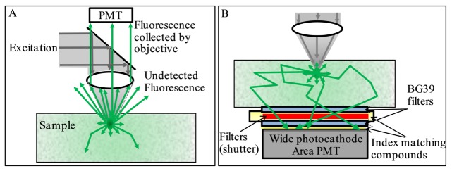
Imaging in depth in a scattering environment with spatial variations has been particularly challenging, with most attempts on commercial systems reaching imaging depth only in the hundreds of microns. A problem associated with in-depth fluorescence imaging is the harvesting of fluorescence photons. Here we discuss the collection of photons after they have been produced. Another major area of research in this field is the efficiency of excitation that could require adaptive optics to compensate for different optical paths [10–13]. Although very important, in this paper we are not discussing the excitation process but only the collection of the emitted light. In most two-photon fluorescence microscopes the fluorescence is collected by the same microscope objective used for excitation (epi-detection). This design limits collection of fluorescence photons to a relatively small area of the sample and acceptance angle of the objective lens, leaving most of the fluorescence photons undetected, as schematically shown in Fig. 1(A).
Fig. 1.
A- Conventional epi-detection: fluorescence photons collected from a narrow sample area at a limited acceptance angle, most photons remain undetected. B- DIVER detection: photons collected from a wide sample area at wide angle; refractive index in optical path “sample - detector” is matched to minimize photon loses due to reflections, so photons may enter the detector at virtually any angle.
To address this problem several approaches were reported in the literature. One approach [14–16] describes the use of a parabolic mirror to reflect these missed photons back to detector and that may increase the signal gain by factor of 2 to 5. Alternatively, the additional collection of fluorescence photons by a ring of optical fibers, surrounding an objective, may enhance fluorescence collection efficiency by factor of 5 [17,18]. It was also shown that the specially designed objective with embedded beam splitter [19] may enhance fluorescence collection by a factor of 10 compared to existing objective lens designs.
In the DIVER (Deep Imaging Via Emission Recovery) detection scheme, Fig. 1(B), the excitation and detection optics are separated, that allows more efficient collection of fluorescence photons. The details of detector construction, principles of its operation and application to deep imaging in turbid samples, including biological tissues, can be found in [20–22]. In turbid media, fluorescence photons emitted from the focal area are scattered by the media and the number of emitted photons reaching a certain surface area of the sample is attenuated mainly by absorption. However, scattering increases the path length that photons need to travel to the detector, which increases the probability that they will be absorbed.
The DIVER detection scheme collects the scattered fluorescence photons reaching the surface of the sample with minimum losses. It is based on two concepts: 1) the use of a wide area detector; 2) maintaining the uniformity of the refractive index in the optical path from the sample surface to the detector. Scattered emission photons are collected from a wide area of a sample surface (300-500mm2), while photon losses associated with reflections at optical surfaces (including total internal reflection) are minimized by the proper use of refractive index matching fluids. Matching the refractive index in the optical path “sample – detector” allows scattered photons (which may exit the sample in any possible direction) to enter the detector at virtually any angle and not be rejected by reflection at an interface between media with different indices.
In this paper we present a quantitative comparison of the two-photon excitation imaging of tissue phantoms and a mouse brain tissue sample using DIVER and epi-detection schemes at the same time and show that, depending on the imaging depth and turbidity of the sample, the DIVER detector could be up to 3 orders of magnitude more sensitive than conventional epi-detection. This quantitative comparison was not done in previous publications where only images acquired at different depths with the DIVER detector were compared with images acquired with a commercial instrument in epi mode (Zeiss LSM 710 NLO). Here we directly compare images acquired simultaneously within the same microscope using the DIVER detector in transmission and another detector in epi configuration. Using the same instrument and the same illumination conditions allowed us to perform a quantitative comparison between the DIVER and the epi detector. In this paper we are able to quantify the gain obtained by the DIVER detector over the conventional epi acquisition mode. We will like to emphasize that the DIVER detector is not just a detector placed in the transmission path. The DIVER detector is constructed to avoid total reflection at large angles by carefully matching the index of refraction along the entire optical path from the point of emission to the detector active surface (Fig. 1(B)). Since the light passes through the detector at very large angles of incidence, the DIVER detector cannot utilize interference filters and the glass filters used in the DIVER must be immersed in the index matching fluid as shown in Fig. 1(B).
2. Experiment
2.1 Sample preparation
Samples used in these experiments were prepared by mixing Fluorescent Yellow-Green Beads of 1μm size (Invitrogen, F8762) and Titanium Dioxide powder for scattering (AEE, Bergenfield, NJ, TI-602, particle size 0.3-1μm) in 3% Gelatin (Sigma-Aldrich, G2500) solution in hot water. India Ink (RAPIDRAW 3084-F, Bloomsbury, NJ) was used to induce absorption. The warm liquid solutions were poured into 35mm Petri dishes (MatTek, Ashland, MA, P35G-1.5-14-C) and solidified at room temperature. Solution volumes were adjusted to make samples of 3mm and 10 mm thickness.
The amount of India Ink was adjusted to make samples with an absorption coefficient of μa = 0.1mm−1 at 515nm fluorescence maximum of beads. Amounts of Titanium Dioxide particles were 2.4mg/ml and 0.8mg/ml of solution to generate samples with scattering coefficients μs approximately equal to 10mm−1 and 3.5mm−1 respectively at 800nm excitation wavelength. The values of scattering coefficients were estimated from fluorescence signal intensity (F) decay with imaging depth (z), assuming exponential decay of excitation photons intensity vs. imaging depth [2]: F ∝ exp(−2μsz). These absorption and scattering coefficient values approximately correspond to what can be found in brain tissue samples [6].
The Thy1-YFP-H mouse brain sample used for imaging was a paraformaldehyde-fixed brain from B6.Cg-Tg(Thy1-YFP)HJrs/J mouse (The Jackson Lab., Stock No:003782,). The approximately 3 mm size sample of the hippocampus region of the brain was embedded in the 3 mm thick scattering media containing TiO2 particles (μs = 3.5mm−1) to match the DIVER detector size so as to collect the photons from a wide sample area.
2.2 Experimental system
Details of the DIVER detector construction can be found in [20–22]. Briefly, a photomultiplier tube (PMT) (Hamamatsu R7600P-300) with 18x18mm photocathode area was attached to the chamber with filters/shutter and filled with an index matching liquid (i.e. propylene glycol), as shown in Fig. 1(B). Two BG39 filters (Schott) of 25mm diameter were used as windows to seal the chamber and also to block the excitation laser light. Samples were placed directly on the top window of the DIVER detector. A drop of water was used to fill the air gap between the sample and the detector window to reduce reflections; for the same reason a drop of index matching microscope oil was used to fill the gap between the PMT and the bottom window of the chamber. This simple in-construction detector allows for efficient collection of the fluorescence photons induced in the turbid sample, from the wide area of the sample surface and at practically any entrance angle, which results in more photons being collected.
The custom made imaging system, schematically shown in Fig. 2(A), utilizes the InSight DS + laser (Spectra Physics) for imaging fluorescent samples by two-photon excitation; it is also equipped with an epi-detector (Hamamatsu H7422P-40), which is used as a second channel detector and, for the purpose of this paper, to compare performance of the DIVER and epi-detection schemes.
Fig. 2.
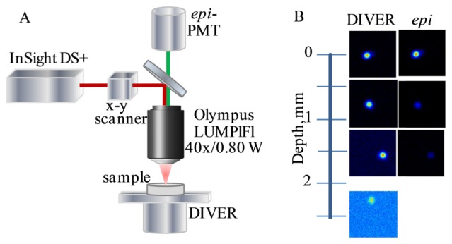
A- Experimental system. B- Images of fluorescent beads by the DIVER and epi-detector at various depths in the scattering sample (μs = 3.5mm−1).
Data acquisition and analysis was performed using the SimFCS software developed at the Laboratory for Fluorescence Dynamics and commercially available as Globals for Images (www.lfd.uci.edu). Images (256 x 256 pixels) were averaged over 10 frames; the pixel dwell time was 32μs.
3. Results and discussion
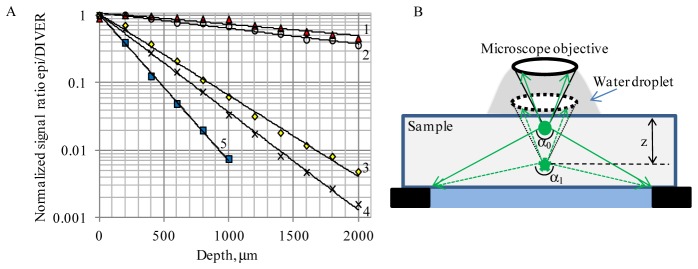
To compare relative performances of the DIVER and epi-detection schemes we have imaged fluorescent beads in gelatin matrices using the experimental system shown schematically in Fig. 2(A). Because the two PMTs used have different characteristics (such as spectral response, quantum efficiency, dark counts etc.), the light detected by the detectors must first be normalized. We set up experimental conditions so that signals measured by both detectors at the surface of a clear sample (with only fluorescent beads embedded) were approximately at the same level. Then we measured the ratio of the signals from epi-detector to the DIVER detector (normalized to 1 at the sample surface) and plotted it as a function of imaging depth (Fig. 3).
Fig. 3.
A- Plot of normalized signal ratio epi/DIVER detectors vs. imaging depth in 3mm thick samples: 1- clear sample (no ink and TiO2 added); 2- sample with ink added (μa = 0.1mm−1, no TiO2); 3- sample with lower scattering (μs = 3.5mm−1, no ink); 4- sample with lower scattering and ink (μs = 3.5mm−1; μa = 0.1mm−1); 5- sample with higher scattering (μs = 10mm−1, no ink). λexc 800nm. B- Explanation for better DIVER performance at increased imaging depth in clear samples: the effective NA for the DIVER detector increases with depth, while remains the same for the epi-detector.
In clear samples (curve 1 in Fig. 3(A)) the ratio decreases slightly with imaging depth, showing that the DIVER detector collects more fluorescence photons at higher depths than the epi-detector, while close to the sample surface, the efficiencies of both detectors are similar. The depth dependence in the clear sample shows that at higher imaging depths (z) the focal point (where two-photon fluorescence is induced) moves toward the DIVER detector and out of the epi-detector therefore increasing the effective collection angle of the DIVER detector (α1>α0). In the epi-detector the collection angle does not change as shown in Fig. 3(B). Adding an absorber to the sample (curve 2) further increases the line slope because the route is shorter and there is less absorption of fluorescence photons in the DIVER detector and conversely more absorption in the epi-detector as the distance increases.
In scattering samples the signal ratio significantly decreases with imaging depth and the DIVER detector becomes much more efficient than the epi-detector. Curve 3 in Fig. 3(A) shows that at a 2mm imaging depth the signal from the DIVER detector is about 250 times stronger than the signal from the epi-detector, which makes the DIVER detector much more efficient for imaging in multiple scattering media in depth. Indeed, as shown in Fig. 2(B), fluorescent beads in the sample can only be imaged by the epi-detector to the depth of about 700μm, after that the image intensity becomes too weak, while using the DIVER detector, fluorescent beads in the same sample can easily be imaged to a depth of 2.5mm and deeper. It should be noted that, in the absence of strong absorption, attenuation of the fluorescence signal (due to multiple scattering in the sample) is linear with the distance [2] and, to a certain extent, this is compensated by the shorter distance at higher depths for the DIVER detection scheme. This makes the DIVER detector very suitable for imaging (10mm and more) in turbid samples.
The signal ratio decay in the scattering sample is faster in the epi/DIVER with induced absorption than it would be without absorption, curve 4 in Fig. 3(A). For this sample, when imaging depths exceeded 2mm, the measured DIVER detector performance was about 1000 times more efficient than the epi-detector. An increase in scattering characteristics of the sample also leads to an increase in signal ratio epi/DIVER decay rate with imaging depth, curve 5 in Fig. 3(A), making the DIVER detection scheme preferable for imaging turbid samples at very large depths.
The transmission geometry of the DIVER detection scheme (where excitation and signal detection are performed from opposite sides of the sample and emission photons must travel through the media thickness to reach the detector) does put certain limitations on samples that can be imaged. Nevertheless, this method does allow imaging of a vast variety of samples, including biological tissues, making it a useful addition to conventional epi-detection, especially when deeper sample layers need to be imaged. The main limitation is due to attenuation of the signal in samples that have strong absorption at the emission wavelength. In this case the signal is attenuated according to the optical path that photons travel from the focal point to the detector, which increases in multiple scattering samples.
We studied the effect of sample thickness and absorber presence on the relative signal strength, to show that the absorption of the fluorescence is the major limiting factor for deep imaging with the DIVER detector, Fig. 4.
Fig. 4.
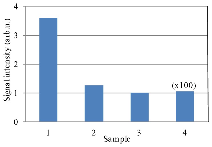
Effect of sample thickness and absorber on signal intensity for the DIVER detector. Scattering samples (μs = 3.5mm−1) are: 1- 3mm thick (no ink); 2- 3mm thick, ink added (μa = 0.1mm−1); 3- 10mm thick (no ink); 4- 10mm thick, ink added (μa = 0.1mm−1). λexc was 800nm.
Fluorescent beads were imaged at the surface layer of scattering samples of various thickness and composition, and signal intensities were recorded. The intensity value for sample 3 was used to normalize all data presented in Fig. 4. Adding absorber to the 3mm thick sample attenuates signal by approximately a factor of 3 (comparison between samples 1 and 2). Increasing sample thickness from 3mm to 10mm (comparison between samples 1 and 3) also leads to signal attenuation by a factor of ~3.6, but adding absorber to 10mm thick sample significantly attenuates the signal by a factor of ~100 (comparison between samples 3 and 4) due to internal fluorescence absorption.
Where absorption is negligible, the scattered photons always have a chance to be redirected and reach the detector, so even samples above 1cm thick can easily be imaged in transmission geometry. In the presence of the absorber, the detected signal significantly depends on the sample thickness, which may render such samples unsuitable for imaging with the DIVER detector and make the epi-detection scheme preferable. In many biological tissues, absorption is due to blood. Emission at longer wavelengths where blood absorption is minimal will substantially increase the imaging depth.
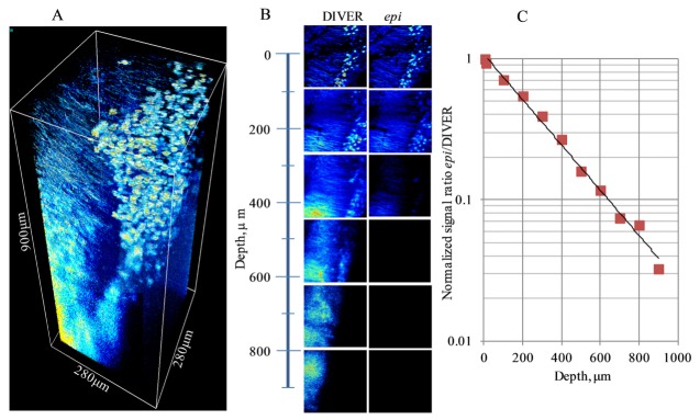
To compare The DIVER and the epi- detector efficiency in a biological tissue we have imaged a brain hippocampus of Thy1-YFP-H transgenic mouse that express yellow fluorescent protein in neurons, Fig. 5.
Fig. 5.
Imaging of the Thy1-YFP mouse brain sample: A- 3D image acquired with the DIVER detector; B- images of layers at various depth acquired by the DIVER and the epi- detectors (compared in the same intensity scale); C- plot of signal ratio epi/DIVER detectors vs. imaging depth. λexc was 970nm.
The stack of images was acquired to 900μm depth of the sample with 5μm step between layers. The laser power was automatically adjusted to compensate for fluorescence intensity decay with imaging depth. Figure 5(A) shows the 3D image of the sample reconstructed from the acquired stack of layers. Axons and cell bodies are well resolved in the top layers of the image, but at depths below 400-500μm the image becomes blurred and, while a cell body still can be recognized, individual axons are not resolved. This loss of resolution with imaging depth is related to wavefront and point spread function deformation due to sample inhomogeneity [10], which is much higher in biological tissues than in tissue phantoms as presented in the data of Fig. 3. For instance, tissue phantoms, which are much more homogeneous and don’t have such variations in refractive index, can be imaged at mm depth without losing resolution.
Figure 5(B) shows images of individual layers at certain sample depths, which were acquired by the DIVER and the epi- detectors. To compare images the intensity scale for each pair of images was set the same. The initial image intensity at the sample surface was approximately the same for both detectors, however, as the imaging depth increases the DIVER detector becomes more sensitive and below approximately 500μm the images acquired by the epi-detector start to disappear, but can still be seen clearly with the DIVER detector. Quantitatively, this is shown in Fig. 5(C), where the signal ratio from epi/DIVER detector is plotted as a function of imaging depth. As shown, the DIVER detector becomes about 30 times more efficient at 900μm depth than the epi-detector.
4. Conclusions
We have shown that the DIVER detection scheme, which utilizes a wide area detector and matching index of refraction in the optical path “sample-detector” may be very efficient for imaging turbid samples in depth compared to a traditional epi-detection scheme. This simple in-construction and implementation method collects emission photons directly from a wide area of a turbid sample, while epi-detection is limited by a relatively narrow area and angle in which photons can be collected. The DIVER detector performs much better at larger imaging depths compared to epi-detection allowing imaging of deeper layers in turbid media where the epi-detector cannot detect due to weak emission signals at those depths. As it was also shown elsewhere [22–24], the DIVER detection scheme is particularly useful for harmonics generation imaging, since these types of radiation are intrinsically forward directed and transmission geometry becomes preferable.
Although transmission geometry imposes certain limitation on samples, the method is useful for imaging in depth a variety of samples, including biological tissues. One recognized limitation for imaging depth in turbid media [3] is due to out-of-focus fluorescence, which is induced at the sample surface by high intensity excitation light, used to compensate for fluorescence signal decay at higher imaging depths. This out-of-focus fluorescence masks the imaging signal and makes deeper imaging impossible. In case of the DIVER detection scheme this out-of-focus fluorescence limitation is less pronounced, because in-focus photons travel shorter distances through the sample to the detector than out-of-focus photons from the sample surface which are attenuated. In fact, we have found that for the DIVER detector the major factor which limits imaging depth in turbid samples is a wavefront distortion due to refractive index inhomogeneity that potentially can be compensated for by means of adaptive optics [10–13] in addition to absorption of the fluorescence. Absorption of fluorescence becomes a limiting factor in tissue samples where absorption due to blood is strong below about 650nm while absorption of the excitation has a lesser effect. When the sample is strongly scattering, but the medium is relatively homogeneous, such as the tissue phantoms used in this paper, it can be imaged by the DIVER to mm depths without losing resolution [20]. However, in biological tissue samples, depending on tissue origin and optical properties, at certain depths the image loses resolution and becomes blurred, which usually happens before the out-of-focus fluorescence starts to dominate the signal. Yet, using the DIVER we were able to image such samples at much deeper layers than by commercial two-photon microscopes equipped with epi-detectors [20–22].
Acknowledgments
We are also grateful to Dr. Jessica L. Bolton and Dr. Tallie Z. Baram for providing us with the Thy1-YFP mouse brain sample.
Funding
This work was supported by Grants NIH P41GM103540, P50GM076516.
References and links
- 1.Denk W., Strickler J. H., Webb W. W., “Two-photon laser scanning fluorescence microscopy,” Science 248(4951), 73–76 (1990). 10.1126/science.2321027 [DOI] [PubMed] [Google Scholar]
- 2.Helmchen F., Denk W., “Deep tissue two-photon microscopy,” Nat. Methods 2(12), 932–940 (2005). 10.1038/nmeth818 [DOI] [PubMed] [Google Scholar]
- 3.Theer P., Denk W., “On the fundamental imaging-depth limit in two-photon microscopy,” J. Opt. Soc. Am. A 23(12), 3139–3149 (2006). 10.1364/JOSAA.23.003139 [DOI] [PubMed] [Google Scholar]
- 4.Jacques S. L., “Optical properties of biological tissues: a review,” Phys. Med. Biol. 58(11), R37–R61 (2013). 10.1088/0031-9155/58/11/R37 [DOI] [PubMed] [Google Scholar]
- 5.Cheong W., Prahl S. A., Welch A. J., “A Review of the Optical Properties of Biological Tissues,” IEEE J. Quantum Electron. 26(12), 2166–2185 (1990). 10.1109/3.64354 [DOI] [Google Scholar]
- 6.Yaroslavsky A. N., Schulze P. C., Yaroslavsky I. V., Schober R., Ulrich F., Schwarzmaier H. J., “Optical properties of selected native and coagulated human brain tissues in vitro in the visible and near infrared spectral range,” Phys. Med. Biol. 47(12), 2059–2073 (2002). 10.1088/0031-9155/47/12/305 [DOI] [PubMed] [Google Scholar]
- 7.Kobat D., Durst M. E., Nishimura N., Wong A. W., Schaffer C. B., Xu C., “Deep tissue multiphoton microscopy using longer wavelength excitation,” Opt. Express 17(16), 13354–13364 (2009). 10.1364/OE.17.013354 [DOI] [PubMed] [Google Scholar]
- 8.Dunn A. K., Wallace V. P., Coleno M., Berns M. W., Tromberg B. J., “Influence of optical properties on two-photon fluorescence imaging in turbid samples,” Appl. Opt. 39(7), 1194–1201 (2000). 10.1364/AO.39.001194 [DOI] [PubMed] [Google Scholar]
- 9.Singh A., McMullen J. D., Doris E. A., Zipfel W. R., “Comparison of objective lenses for multiphoton microscopy in turbid samples,” Biomed. Opt. Express 6(8), 3113–3127 (2015). 10.1364/BOE.6.003113 [DOI] [PMC free article] [PubMed] [Google Scholar]
- 10.Ji N., Milkie D. E., Betzig E., “Adaptive optics via pupil segmentation for high-resolution imaging in biological tissues,” Nat. Methods 7(2), 141–147 (2010). 10.1038/nmeth.1411 [DOI] [PubMed] [Google Scholar]
- 11.Vellekoop I. M., Mosk A. P., “Focusing coherent light through opaque strongly scattering media,” Opt. Lett. 32(16), 2309–2311 (2007). 10.1364/OL.32.002309 [DOI] [PubMed] [Google Scholar]
- 12.Watson B. O., Nikolenko V., Yuste R. I., “Two-photon imaging with diffractive optical elements,” Front. Neural Circuits 3(6), 1–11 (2009). [DOI] [PMC free article] [PubMed] [Google Scholar]
- 13.Cha J. W., Ballesta J., So P. T. C., “Shack-Hartmann wavefront-sensor-based adaptive optics system for multiphoton microscopy,” J. Biomed. Opt. 15(4), 046022 (2010). 10.1117/1.3475954 [DOI] [PMC free article] [PubMed] [Google Scholar]
- 14.Combs C. A., Smirnov A. V., Riley J. D., Gandjbakhche A. H., Knutson J. R., Balaban R. S., “Optimization of multiphoton excitation microscopy by total emission detection using a parabolic light reflector,” J. Microsc. 228(3), 330–337 (2007). 10.1111/j.1365-2818.2007.01851.x [DOI] [PubMed] [Google Scholar]
- 15.Combs C. A., Smirnov A., Chess D., McGavern D. B., Schroeder J. L., Riley J., Kang S. S., Lugar-Hammer M., Gandjbakhche A., Knutson J. R., Balaban R. S., “Optimizing multiphoton fluorescence microscopy light collection from living tissue by noncontact total emission detection (epiTED),” J. Microsc. 241(2), 153–161 (2011). 10.1111/j.1365-2818.2010.03411.x [DOI] [PMC free article] [PubMed] [Google Scholar]
- 16.Combs C. A., Smirnov A., Glancy B., Karamzadeh N. S., Gandjbakhche A. H., Redford G., Kilborn K., Knutson J. R., Balaban R. S., “Compact non-contact total emission detection for in vivo multiphoton excitation microscopy,” J. Microsc. 253(2), 83–92 (2014). 10.1111/jmi.12099 [DOI] [PMC free article] [PubMed] [Google Scholar]
- 17.Flusberg B. A., Cocker E. D., Piyawattanametha W., Jung J. C., Cheung E. L. M., Schnitzer M. J., “Fiber-optic fluorescence imaging,” Nat. Methods 2(12), 941–950 (2005). 10.1038/nmeth820 [DOI] [PMC free article] [PubMed] [Google Scholar]
- 18.Engelbrecht C. J., Göbel W., Helmchen F., “Enhanced fluorescence signal in nonlinear microscopy through supplementary fiber-optic light collection,” Opt. Express 17(8), 6421–6435 (2009). 10.1364/OE.17.006421 [DOI] [PubMed] [Google Scholar]
- 19.McMullen J. D., Zipfel W. R., “A multiphoton objective design with incorporated beam splitter for enhanced fluorescence collection,” Opt. Express 18(6), 5390–5398 (2010). 10.1364/OE.18.005390 [DOI] [PMC free article] [PubMed] [Google Scholar]
- 20.Crosignani V., Dvornikov A. S., Gratton E., “Enhancement of imaging depth in turbid media using a wide area detector,” J. Biophotonics 4(9), 592–599 (2011). [DOI] [PMC free article] [PubMed] [Google Scholar]
- 21.Crosignani V., Dvornikov A., Aguilar J. S., Stringari C., Edwards R., Mantulin W. W., Gratton E., “Deep tissue fluorescence imaging and in vivo biological applications,” J. Biomed. Opt. 17(11), 116023 (2012). 10.1117/1.JBO.17.11.116023 [DOI] [PMC free article] [PubMed] [Google Scholar]
- 22.Crosignani V., Jahid S., Dvornikov A. S., Gratton E., “A Deep Tissue Fluorescence Imaging System with Enhanced SHG Detection Capabilities,” Microsc. Res. Tech. 77(5), 368–373 (2014). 10.1002/jemt.22354 [DOI] [PMC free article] [PubMed] [Google Scholar]
- 23.Ranjit S., Dvornikov A., Stakic M., Hong S. H., Levi M., Evans R. M., Gratton E., “Imaging Fibrosis and Separating Collagens using Second Harmonic Generation and Phasor Approach to Fluorescence Lifetime Imaging,” Sci. Rep. 5, 13378 (2015). 10.1038/srep13378 [DOI] [PMC free article] [PubMed] [Google Scholar]
- 24.Datta R., Alfonso-García A., Cinco R., Gratton E., “Fluorescence lifetime imaging of endogenous biomarker of oxidative stress,” Sci. Rep. 5, 9848 (2015). 10.1038/srep09848 [DOI] [PMC free article] [PubMed] [Google Scholar]


