Abstract
Many experimental biological techniques utilize hollow glass needles called micropipettes to perform fluid extraction, cell manipulation, and electrophysiological recordings For electrophysiological recordings, micropipettes are typically fabricated immediately before use using a “pipette puller”, which uses open-loop control to heat a hollow glass capillary while applying a tensile load. Variability between manufactured micropipettes requires a highly trained operator to qualitatively inspect each micropipette; typically this is achieved by viewing the pipette under 40–100x magnification in order to ensure that the tip has the correct shape (e.g., outer diameter, cone angle, taper length). Since laboratories may use hundreds of micropipettes per week, significant time demands are associated with micropipette inspection. Here, we have automated the measurement of micropipette tip outer diameter and cone angle using optical microscopy. The process features repeatable constraint of the micropipette, quickly and automatically moving the micropipette to bring its tip into the field of view, focusing on the tip, and computing tip outer diameter and cone angle measurements from the acquired images by applying a series of image processing algorithms. As implemented on a custom automated microscope, these methods achieved, with 95% confidence, ±0.38 µm repeatability in outer diameter measurement and ±5.45° repeatability in cone angle measurement, comparable to a trained human operator. Accuracy was evaluated by comparing optical pipette measurements with measurements obtained using scanning electron microscopy (SEM); optical outer diameter measurements differed from SEM by 0.35 ± 0.36 µm and optical cone angle measurements differed from SEM by −0.23 ± 2.32°. The algorithms we developed are adaptable to most commercial automated microscopes and provide a skill-free route to rapid, quantitative measurement of pipette tip geometry with high resolution, accuracy, and repeatability. Further, these methods are an important step toward a closed-loop, fully-automated micropipette fabrication system.
Keywords: micropipette, image processing, microscope
1. Introduction
Glass micropipettes (or “pipettes”) are hollow, tapered needles with tip outer diameters ranging from nominally 0.5 µm to 75 µm. They are critical for biological techniques including microinjection [1], in vitro fertilization [2], and electrical recording of neural activity [3], each of which requires micropipette tips of different diameters and taper angles, or “cone angles”. Typical applications may require hundreds to thousands of pipettes (e.g., patch clamp electrophysiology may consume 100 pipettes per day [3]).
Micropipettes are susceptible to breakage and contamination, and so they are preferably fabricated immediately before use by commercially-available “pipette pullers” (e.g., Sutter Instrument, Novato, CA) [2, 4]. All pipette pullers use open-loop control to heat a glass capillary while applying a tensile load, using either constant force [2] or constant velocity [5], until the capillary necks and fractures into two virtually identical micropipettes.
Pipette tip diameter tolerances are highly application dependent. For demanding in vivo electrophysiology applications, for example, operators typically desire micropipettes within 15% of the target tip diameter [3]. To maintain these tolerances, frequent (i.e., weekly to monthly) calibration is necessary to “tune” pipette pullers, a process in which a highly trained operator iteratively adjusts pulling parameters (e.g., heating time, cooling time, pull velocity) to achieve micropipettes of the desired geometry (e.g., tip diameter, cone angle, taper length). At each iteration, the operator pulls a micropipette, views the tip under 40–100x magnification, and then uses experience and written guides (e.g., [2]) to adjust puller settings. This process can take several hours, and in some cases, over 100 iterations may be required to obtain suitable micropipettes. Once calibration is achieved, regular microscopic inspection is still performed to verify that drift or manufacturing process variation remains within tolerances. Due to the time demands associated with manual pipette inspection (1–3 minutes per pipette), a method for rapid, automated, quantitative inspection of pipette tip geometry is therefore desirable.
Several methods exist for quantitatively measuring micropipette tip geometry. Scanning electron microscopy (SEM) is the “gold standard”, but it is slow (∼6–10 pipettes per hour), labor-intensive, and expensive [6]. Typically, the inspection is also destructive, and thus it is not suitable for routine pipette inspection.
A second technique measures tip inner diameter by submerging the pipette tip in fluid and bubbling air through the aperture. The inner diameter of the pipette tip can be determined from knowledge of the pneumatic pressure required to overcome surface tension forces and force air out of the pipette tip [7]. This “bubbling” technique is fast, provides a quantitative measure of tip inner diameter, and can be automated. However, the technique provides no information about cone angle, which is critical for some applications [8].
A third technique, used often in the field of electrophysiology, uses the electrical resistance of a fluid-filled micropipette as a proxy for its tip geometry. Using this technique, the pipette is filled with an electrically conductive fluid, a current is applied, and the micropipette’s electrical resistance is computed as the ratio of the voltage drop across the tip to the applied current. This resistance is a function of the interior geometry of the pipette, and is dominated by the tip diameter and cone angle. Since this method is indirect, reducing the complex tip geometry to a single number, it is typically accompanied by a manual, qualitative visual inspection of the tip using a microscope with 40–100x magnification. Pipette resistance is a useful heuristic for electrophysiologists and is regularly referenced in the literature [9–11], but it is of little use in other applications and is insufficient for pipette puller tuning.
To address weaknesses in current options for rapid and quantitative inspection of micropipette tip geometry, we developed and implemented a set of algorithms to perform automated optical measurement of pipette tip geometry using a microscope with a motorized stage. The algorithms, sequentially, (1) automatically move the micropipette tip into the field of view, (2) focus on the tip, and (3) measure tip outer diameter and cone angle by applying a series of image processing computations. We describe the algorithms and their implementation, then discuss characterization of their performance in terms of the accuracy and repeatability of the resulting tip diameter and cone angle measurements.
2. Methods
2.1 Microscope and micropipette fixture
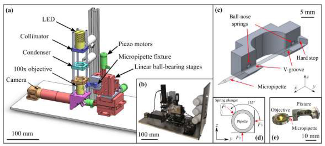
To implement the pipette tip inspection algorithms, we constructed a custom automated microscope (Fig. 1a–b), but these generalizable algorithms could conceivably be adapted to most commercial automated microscopes. Our microscope comprised an LED (Thorlabs, 590 nm), collimator (Thorlabs, LA1027), condenser (Thorlabs, ACL2520-A), finite conjugate objective (1.25 NA/100x), and camera (Edmund Optics, EO-1312M). The image was relayed from the finite conjugate objective to the camera by a flat fold mirror to reduce the physical height of the imaging system. The objective lens was immersed in 0.2 µm-filtered deionized water resulting in optical resolution of 461 nm (based on the Rayleigh criterion), pixel size of 52 nm/pixel (nm/px), and a field of view of 29 µm x 45 µm. No attempt was made to correct for aberrations in the acquired images. A motorized three-axis positioner was assembled using three linear ball-bearing stages (Newport 460A) and three linear piezo motors (Newport PZA12). The camera and motors were controlled via an interface developed in MATLAB.
Fig. 1.
(a) Schematic of the automated microscope used for measurement of glass micropipette tip geometry, with (b) photograph of system as implemented. (c) Motorized fixture for kinematic constraint of the pipette, using a pair of ball-nose spring plungers to preload the pipette in aluminum V-grooves, resulting in (d) intersecting lines of force, which locate the center of stiffness along the axis of the pipette. Pipettes were constrained in y and z by the V-grooves and registered to a hard stop in the x direction. (e) Photograph of fixture as fabricated positioning a pipette over the objective.
For rapid, repeatable constraint of pipettes for imaging within the microscope, an aluminum fixture (Fig. 1c–e) was designed and fabricated. The fixture, which was mounted on the three-axis positioner, accepted micropipettes into a V-groove to position the tips for imaging. Within the fixture, ball-nose spring plungers preloaded pipettes into the V-groove in the radial direction, and pipettes were registered to a hard stop in the axial direction by the operator. Contact forces from the fixture located the center of stiffness along the pipette centerline (Fig. 1d). The fixture was secured to the three-axis positioner at a 15° tilt relative to the x-y plane to allow the tapered tip the be positioned within the working distance of the objective (∼100 µm).
2.2 Pipette tip-finding algorithm
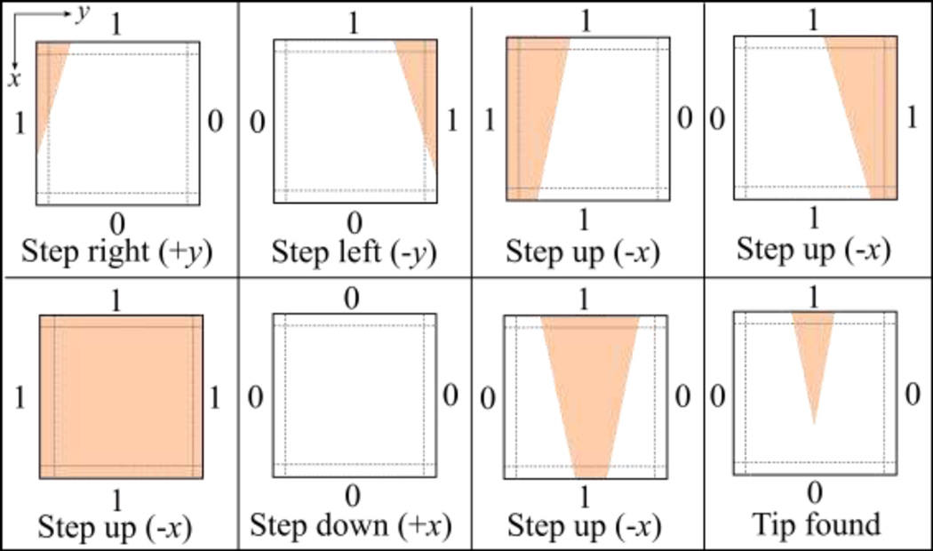
To find the pipette tip in the field of view, a search strategy was developed that translated the pipette based upon features visible in each image acquired by the camera. First, a background image was captured when the system was initialized and was subtracted from future images to compensate for non-uniform illumination. A boundary region (30 pixels wide) was then identified along each edge of each image. Within each boundary region, if the maximum pixel intensity was greater than a user-specified threshold, the edge was encoded as “1”, indicating that part of the pipette was visible along that edge of the image. Otherwise, no part of the pipette was visible along that edge of the image and the edge was encoded as “0”.
Fig. 2 shows the eight possible edge conditions encountered during tip-finding and the pipette movements resulting from each. When a pipette was first inserted and nothing was detected in the field of view (all edges equal “0”), the pipette was moved in 10 µm steps in the axial direction (+x) repeatedly until a different edge condition was detected. The result of this search strategy was that pipettes followed a “zig-zag” path in the x-y plane until the tip entered the field of view (Fig. 2, lower right)
Fig. 2.
Search strategy for the pipette tip-finding algorithm. Pipettes were repeatedly moved in 10 µm steps; the step direction was determined by detecting whether some part of the pipette was (1) or was not (0) present in a boundary region along each edge of the image. Pipettes were moved iteratively until the tip entered the field of view and the final condition (lower right) was encountered.
2.3 Autofocus algorithm
Autofocusing is a well-studied problem in machine vision [12–14]. To focus on the pipette when it is in the field of view, we implemented a basic autofocus algorithm based on the Laplacian variance focus measure [15].
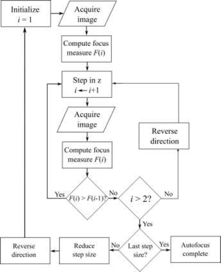
A flowchart of the autofocus algorithm is shown in Fig. 3. An initial image (i = 1) was captured and its focus measure, F(1), was computed. The pipette was moved one 20 µm step in the +z direction (away from the objective), then another image was acquired. If F decreased after this initial step, i.e., F(2) < F(1), then the step direction was reversed since the initial step was in the wrong direction. The pipette then continued moving (in 20 µm steps) in one direction until a decrease in F occurred, i.e., until F(i) < F(i-1), indicating that a local maximum in focus had been crossed. After a local maximum was crossed, the step direction was reversed and the method was repeated with the next step size (sequentially: 20 µm, 5 µm, 2 µm, 0.5 µm) to obtain increasingly fine focus on the pipette tip.
Fig. 3.
An autofocus algorithm captured pipette images, computed their Laplacian variance focus measure, and then moved the pipette accordingly to maximize focus. The pipette was moved in one direction until the focus measure crossed a local maximum, then the direction was reversed and the process was repeated with the next step size (sequentially: 20 µm, 5 µm, 2 µm, 0.5 µm) to obtain increasingly fine focus on the pipette tip.
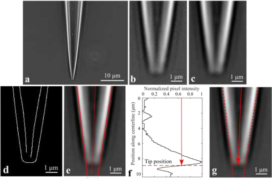
Once the pipette tip was in focus, ten frames were captured and averaged to reduce noise effects, and the previously-captured background image was subtracted (shown in Fig. 4a). The resulting image was cropped around the pipette tip by removing all rows and columns which fell below a user-defined threshold mean pixel intensity. The image was cropped further to only the bottom 200 remaining rows (∼10.4 µm), as shown in Fig. 4b.
Fig. 4.
A series of image processing computations were applied to identify the tip outer diameter and cone angle. Pipette tip images: (a) original; (b) cropped; (c) low-pass filtered; (d) Canny edge detection; (e) Hough transform lines and pipette centerline. (f) Normalized intensity of pixels along the pipette centerline, with the axial position corresponding to the tip labeled. (g) Image of pipette tip, with the diameter taken as the separation between the two outer Hough lines at the tip position from (f).
2.4 Tip outer diameter and cone angle measurement algorithm
Fig. 4 uses a typical pipette image to demonstrate the image processing algorithms used to extract tip outer diameter and cone angle measurements. The original pipette image (Fig. 4a) was cropped as described (Fig. 4b). The cropped image was then lowpass filtered by convolving with a discrete Gaussian kernel with standard deviation σ and kernel size n (specifically, σ = 3 px, n = 10 px) to attenuate high spatial frequency components and reduce effects of noise (Fig. 4c). Next, Canny edge detection [16] was applied to the filtered image to trace the inner and outer walls of the pipette, resulting in a binary array the size of the cropped image (Fig. 4d). A linear Hough transform [17] was applied to fit straight lines to the inner and outer walls of the pipette; Fig. 4e plots the lines corresponding to the outer walls. The pipette centerline was then identified in the image; the line was defined by a point (the centroid of the Canny edge detection array) and a slope (the average slope of the two outer lines identified using the Hough transform). To identify the axial position corresponding to the pipette tip, the pixel intensity along the pipette centerline was plotted (Fig. 4f), beginning from the top row of the image. The position of the tip along the centerline was taken as the location where the intensity along the centerline was halfway between the absolute maximum and the following local minimum. The tip outer diameter was then taken as the distance between the two outer Hough lines at the axial tip position identified from the centerline intensity plot (Fig. 4g), allowing sub-pixel diameter measurement resolution.
To calculate cone angle, the angle between the two outer lines identified using the Hough transform was computed. Since pipettes were held at 15° tilt relative to the image plane, this computed cone angle was different from the true cone angle; however, the discrepancy could be corrected for. The equations relating the true cone angle, the measured angle, and the tilt angle are derived in Section 2.5.
Typically, the process of inserting a pipette into the fixture, finding the tip in the field of view, focusing on the tip, and calculating diameter and cone angle measurements was completed in < 30 sec, with the total time mostly determined by the number of steps required for tip-finding and autofocusing. We found that the step rate was limited by the settling time of the pipette tip after it was moved, since stage motions resulted in transverse vibration of the pipette tip and poor image quality. With our particular microscope and stage setup, waiting 500 ms after the pipette was moved before acquiring an image provided an adequate buffer against blurred images.
In practice, slight adjustments to image processing parameters (e.g., edge detection sensitivity) or the position of the pipette were sometimes necessary to obtain suitable diameter and cone angle measurements. These adjustments could easily be made through the software interface used to run the camera and image processing methods.
2.5 Cone angle correction
When pipettes were imaged, they were tilted relative to the optical axis by a tilt angle, α (α = 75° for our custom microscope, i.e., the angle between the pipette axis and the image plane was 15°). Because of this tilt, the angle that was measured in the image, φ, was not the same as the true cone angle, θ. To obtain the relationship between the measured angle, the cone angle, and the tilt angle, two unit vectors and were constructed which began at the pipette tip, pointed along the outer wall of the pipette, and were separated by the cone angle θ. These two vectors were given by Eq. 1 as
| (1) |
where and are orthogonal unit vectors in the image plane, and is along the axis of the pipette. The projection of these two vectors onto the image plane normal to was then
| (2) |
The measured angle, φ, was then related to the tilt angle, α, and the cone angle, θ, by forming the scalar product of these two projected vectors, resulting in
| (3) |
The corrected cone angle could then be obtained by substituting the tilt angle α and the measured angle φ into Eq. 3 and numerically solving for θ.
Correction for tilt angle was judged unnecessary for images taken using our microscope, since at our tilt angle (α = 75°), Eq. 3 predicted cone angle measurement errors (φ – θ) of less than 0.8°. However, the correction was made for cone angle measurements computed from SEM images, which were used to characterize accuracy of our measurements; these images were taken at a tilt of α = 30°, resulting in errors (φ – θ) on the order of 10–15°.
If the tilt angle α were sufficiently small such that tan α < sin (θ/2) , in the image the pipette tip would appear as an ellipse and no projected angle could be measured. However, with a 30° tilt, cone angles up to 71° could be measured, well above the typical pipette cone angle range of 15–30°.
2.6 System characterization
2.6.1 Repeatability of pipette tip positioning
When a new pipette was placed in the fixture, the tip was generally not in the field of view due to (1) uncertainty in the positioning of the pipette by the fixture, and (2) geometric differences between pipettes. To estimate of the volume to be “searched” to find the pipette tip in the 29 µm x 45 µm field of view when a new pipette was placed in the fixture, it was desirable to characterize the repeatability with which the fixture could position a pipette tip in space.
First, a pipette was placed in the fixture and its tip was moved to the center of the field of view. The pipette was then removed from the fixture and replaced. Encoders on the stages measured the displacement required to return the pipette to the center of the field of view, providing a measurement of how far the pipette tip moved relative to the fixture when it was removed from the fixture and replaced. The process was repeated ten times for the same pipette. This provided an estimate of the tip position uncertainty contributed only by the fixture.
Second, since there are significant geometric differences between pipettes, it was desirable to characterize the variation in tip position that occurred when different pipettes were inserted into the fixture. First, a pipette was placed in the fixture and its tip was moved to the center of the field of view. Then, the pipette was removed and a new pipette was inserted into the fixture. Encoders measured the displacement required to return the pipette tip to the center of the field of view. This process was repeated for ten pipettes.
2.6.2 Repeatability of outer diameter and cone angle measurements
The repeatability of outer diameter and cone angle measurements was assessed in two different ways, in order to characterize the different sources of variability between repeated measurements. We aimed first to characterize the sensitivity of the image processing algorithms to small changes in the acquired pipette tip images (e.g., due to noise). A single pipette was inserted into the fixture and thirty images were captured, resulting in thirty outer diameter and cone angle measurements on the same pipette in the same position.
Second, we aimed to characterize the measurement variability that occurred when a pipette was imaged, then removed from the fixture, replaced in the fixture rotated at a random angle about its axis, and imaged again. This process was performed for twenty-five different pipettes, resulting in two outer diameter and cone angle measurements for each. To quantify repeatability, a 95% confidence interval was constructed on the absolute difference between repeated outer diameter or cone angle measurements, i.e., we computed values Δd and Δθ such that P(|d1 – d2| < Δd) = P(|θ1 – θ2| < Δθ) = 95%.
2.6.3 Accuracy of outer diameter and cone angle measurements
To compare our optical measurements to the “gold standard” of scanning electron microscopy, twenty-seven pipette tips were imaged using our system and using a Hitachi SU8230 field emission scanning electron microscope. To mitigate sample charging, samples were imaged with electron energies of 1.5 KeV or less at 1 µA. As a measure of accuracy, we computed the mean ± standard deviation of the difference in outer diameter and cone angle measurements obtained using the SEM and using our methods. Diameter measurements were obtained by imaging pipette tips head-on (i.e., with the optical axis aligned with the pipette axis) and manually fitting an ellipse to the tip circumference using ImageJ. Cone angle measurements were obtained by imaging pipette tips tilted 30° relative to the optical axis and fitting an angle to the outer walls using ImageJ; these measurements were then corrected for the 30° tilt using Eq. 3.
3. Results and Discussion
3.1. Repeatability of pipette tip positioning
When a single micropipette was positioned in the fixture ten times, the measured standard deviation in tip position was sx = 16 µm, sy = 16 µm, sz = 20 µm (total displacement standard deviation 27 µm). When ten different micropipettes were positioned in the fixture, the measured standard deviation in tip position increased to sx = 116 µm, sy = 41 µm, sz = 60 µm (total displacement standard deviation 79 µm). The measured standard deviation in the x direction was especially large because the largest source of variation was the length of the glass capillary used to make the pipettes. Thus, including the effects of pipette-to-pipette geometric variation increased the total displacement standard deviation by nearly a factor of three; the fixture itself caused relatively little variability in tip positioning.
3.2 Repeatability of tip outer diameter and cone angle measurements
The first repeatability study was designed to characterize the sensitivity of the image processing algorithms to small changes in acquired images, e.g., due to noise. Measuring the same pipette thirty times as described resulted in outer diameter measurements of 2.89 ± 0.08 µm, and cone angle measurements of 27.5 ± 1.1°. With 95% confidence, repeated outer diameter and cone angle measurements differed by less than 0.16 µm and 2.2°, respectively. Under these circumstances, the repeatability was limited only by the image processing algorithms, and the resulting variation was much smaller than could be produced by a human pipette inspector.
The second study aimed to characterize the error that occurred when pipettes were imaged, removed from the fixture, and then replaced in the fixture rotated at a random angle about their axis and imaged again. Two outer diameter and cone angle measurements were taken for each of the twenty-seven pipettes as described; Fig. 5a plots the two outer diameter measurements recorded for each pipette. Mean outer diameter measurements ranged from 2.2 µm to 6.2 µm. Repeated measurements on the same pipettes differed by −0.01 ± 0.20 µm (mean ± SD, reported as the first measurement minus the second). Assuming errors were normally distributed, with 95% confidence the measurements differed by less than 0.38 µm (Fig. 5b). The assumption of normality was reasonable given the observed distribution of errors between repeated measurements (Fig. 5c).
Fig. 5.
(a) Results of repeated outer diameter measurements on twenty-seven pipettes. (b) With 95% confidence, the first and second measurements differed by less than 0.38 µm. (c) The distribution of the difference between repeated measurements appeared normal.
The diameter measurement uncertainty (0.38 µm) provides an approximate upper bound on the difference between repeated measurements. This value was reasonable as it was on the order of the optical resolution (0.46 µm), and was also comparable to the uncertainty of measurements produced by a trained human operator. There was no correlation between mean outer diameter and the difference between repeated measurements (Fig. 5b); performance was approximately equal across all pipette sizes. Taken together, these results indicate that removing pipettes from the fixture between measurements more than doubles the diameter measurement uncertainty.
Fig. 6 plots the repeated cone angle measurements. The difference between repeated measurements was 0.38 ± 2.78°. Unlike the diameter measurements, the distribution of the difference between repeated cone angle measurements appeared bimodal (Fig. 6c), possibly due to asymmetry of the micropipette tip around its axis resulting from the fabrication process. Making the conservative approximation that the distribution was normal for the purposes of statistical calculations, however, repeated cone angle measurements differed by less than 5.45° with 95% confidence (Fig. 6b).
Fig. 6.
(a) Results of repeated cone angle measurements on twenty-seven pipettes. (b) With 95% confidence, the first and second measurements differed by less than 5.45°, making the conservative approximation that errors were normally distributed; however, (c) errors were in fact bimodally distributed.
These results indicate that removing pipettes from the fixture between repeated measurements resulted in increased uncertainty (±2.78°) compared to the uncertainty obtained from repeatedly imaging the same pipette without removing it from the fixture (±1.1°).
3.3 Accuracy of tip outer diameter and cone angle measurements
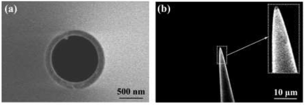
Fig. 7 shows representative pipette images captured using SEM, both head-on to measure outer diameter (Fig. 7a), and at a 30° tilt to measure cone angle (Fig. 7b). The visible protrusion on the inner diameter (Fig. 7a) is a filament adhered to the glass by the manufacturer to provide capillary action to aid in filling the pipette with fluid.
Fig. 7.
Scanning electron microscopy was used to evaluate accuracy of tip outer diameter and cone angle measurements obtained using our optical method. (a) Representative SEM image with no tilt, used to measure outer diameter. (b) Representative SEM image with 30° tilt, used to measure cone angle.
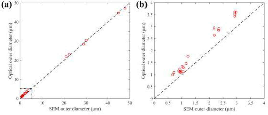
Fig. 8a plots the tip outer diameter measured via SEM versus the tip outer diameter measured using our optical method; the dashed line indicates one-to-one agreement between the measurements. The difference between diameter measurements obtained via SEM and our optical method was 0.35 ± 0.36 µm, before correction for systematic error. For the subset of small (0–3 µm o.d.) pipettes, optical measurements differed from SEM by 0.40 ± 0.19 µm (Fig. 8b).
Fig. 8.
(a) Optical diameter measurements differed from SEM by 0.35 ± 0.36 µm across a wide range of diameters (0–50 µm). (b) For the subset of small (0–3 µm o.d.) micropipettes, optical diameter measurements differed from SEM by 0.40 ± 0.19 µm.
The measured uncertainties were on the order of the optical resolution (461 nm) and comparable to the performance of a skilled human operator, meeting the overall system requirements. Systematic error between optical and SEM measurements could plausibly be explained by partially coherent illumination resulting in an edge profile that was not taken into account by the image processing algorithms. Moreover, since the systematic error was roughly independent of pipette tip size, correcting for it is straightforward.
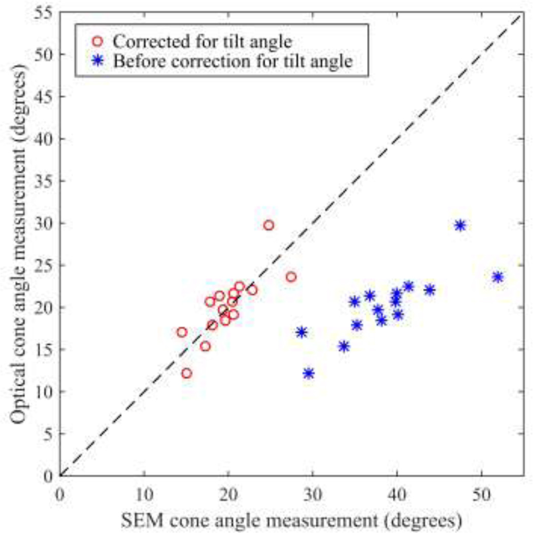
Fig. 9 plots cone angle measurements obtained using SEM and using our optical method. Correcting for the 30° tilt of the pipette relative to the optical axis using Eq. 3 increased agreement between SEM and optical measurements. Optical cone angle measurements differed from SEM by −0.23 ± 2.32°. Again, this performance was comparable to that of a trained human operator, meeting the overall system requirements.
Fig. 9.
Comparison of cone angle measurements obtained using SEM and using our optical method. The dashed line indicates 1-1 agreement. Correcting for the tilt in the SEM image (using Eq. 3) improved agreement. Optical cone angle measurements differed from corrected SEM measurements by −0.23 ± 2.32°.
4. Conclusions
Methods were developed for automated imaging and measurement of micropipette tips, including repeatable pipette constraint, moving a pipette tip into the field of view of the optical system, focusing on the pipette tip, and extracting tip outer diameter and cone angle measurements from the acquired images. Measurements were repeatable: with 95% confidence, repeated outer diameter measurements differed by less than 0.38 µm and repeated cone angle measurements differed by less than 5.45°. Tip diameter measurements differed from SEM, the “gold standard” for imaging pipette tips, by 0.35 ± 0.36 µm, and cone angle measurements differed from SEM by −0.23 ± 2.32°. This performance was comparable to a trained human operator, and thus the algorithms we have presented provide a rapid, skill-free route to quantitative measurement of pipette tip geometry, with accuracy and repeatability on the order of the resolution of the optical system on which they were implemented.
Highlights.
Novel algorithms enable automatic measurement of micropipette tip geometry.
Micropipettes are automatically positioned and imaged using optical microscopy.
100x images are processed to exact tip outer diameter and cone angle measurements.
The algorithms produced accurate measurements, comparing favorably with SEM.
Acknowledgments
CRF acknowledges the NIH BRAIN Initiative Grant (NEI and NIMH 1-U01-MH106027-01), NIH Single Cell Grant 1 R01 EY023173, NSF (EHR 0965945 and CISE 1110947), NIH Computational Neuroscience Training grant (DA032466-02), Georgia Tech Translational Research Institute for Biomedical Engineering & Science (TRIBES) Seed Grant Awards Program, and the Georgia Tech Fund for Innovation in Research and Education (GT-FIRE).
Footnotes
Publisher's Disclaimer: This is a PDF file of an unedited manuscript that has been accepted for publication. As a service to our customers we are providing this early version of the manuscript. The manuscript will undergo copyediting, typesetting, and review of the resulting proof before it is published in its final citable form. Please note that during the production process errors may be discovered which could affect the content, and all legal disclaimers that apply to the journal pertain.
References
- 1.Dean D, Gasiorowski J. Imaging, A Laboratory Manual. New York: CSHL Press; 2010. Preparing injection pipettes on a Flaming/Brown pipette puller. [Google Scholar]
- 2.Oesterle A. Pipette Cookbook 2015: P-97 & P-1000 Micropipette Pullers. California: Sutter Instrument; 2015. [Google Scholar]
- 3.Kodandaramaiah S, Franzesi G, Chow B, Boyden ES, Forest CR. Automated whole-cell patch clamp electrophysiology of neurons in vivo . Nature Methods. 2012;9:585–587. doi: 10.1038/nmeth.1993. [DOI] [PMC free article] [PubMed] [Google Scholar]
- 4.Flaming D. Method and Apparatus for Forming a Micropipette with Uniform Application of Heat. 4,921,522 US Patent. 1990
- 5.Pak N, Dergance MJ, Emergick MT, Gagnon EB, Forest CR. An instrument for controlled, automated production of micrometer scale fused silica pipettes. J Mech Des. 2011:133. [Google Scholar]
- 6.Caldwell M, Del Linz SJL, Smart TG, Moss GWJ. Method for estimating the tip geometry of scanning ion conductance microscope pipets. Anal Chem. 2012;84:8980–8984. doi: 10.1021/ac301851n. [DOI] [PubMed] [Google Scholar]
- 7.Mittman S, Flaming DG, Copenhagen DR, Belgum JH. Bubble pressure measurement of micropipette tip outer diameter. J Neurosci Methods. 1987;22(2):16–16. doi: 10.1016/0165-0270(87)90010-0. [DOI] [PubMed] [Google Scholar]
- 8.Goodman MB, Lockery SR. Pressure polishing: A method for re-shaping patch pipettes during fire polishing. J Neurosci Methods. 2000;100(1–2):13–15. doi: 10.1016/s0165-0270(00)00224-7. [DOI] [PubMed] [Google Scholar]
- 9.Ogden D, Stanfield P. Patch clamp techniques for single channel and whole-cell recording. Currents. 1981;2:53–78. [Google Scholar]
- 10.Sandford C, Moss SG. Thesis. London: University College; 2009. Patch-Clamp Recording of Ion Channels in Cerebellar Interneurons and Granule Cells by Scanning Ion Conductance Microscopy. [Google Scholar]
- 11.Ishikawa D, Takahashi N, Sasaki T, Usami A, Matsuki N, Ikegaya Y. Fluorescent pipettes for optically targeted patch-clamp recordings. Neural Netw. 2010;23(6):669–672. doi: 10.1016/j.neunet.2010.02.004. [DOI] [PubMed] [Google Scholar]
- 12.Groen F, Young I, Ligthard G. A comparison of different focus functions for use in autofocus algorithms. Cytometry. 1985;6:81–91. doi: 10.1002/cyto.990060202. [DOI] [PubMed] [Google Scholar]
- 13.Krotkov E. Focusing. Int J Comp Vision. 1987;1:223–237. [Google Scholar]
- 14.Subarao M, Nikzad A. Focusing techniques. Opt Eng. 1993;32(11):2824–2836. [Google Scholar]
- 15.Bueno-Ibarra M, Alvarez-Borrego J, Acho L, Chavez-Sanchez MC. Fast autofocus algorithm for automated microscopes. Opt Eng. 2005:44. [Google Scholar]
- 16.Canny J. A computational approach to edge detection. IEEE Transactions on Pattern Analysis and Machine Intelligence. 1986;6:679–698. [PubMed] [Google Scholar]
- 17.Ballard J. Generalizing the Hough transform to detect arbitrary shapes. Pattern Recognition. 1981;13:111–122. [Google Scholar]


