Abstract
Chronic hand impairment is common following stroke. This paper presents an actuated thumb exoskeleton (ATX) to facilitate research in examining motor control and hand rehabilitation. The ATX presented in this work aims to provide independent bi-directional actuation in each of the 5 degrees-of-freedom (DOF) of the thumb using a novel flexible shaft based mechanism that has 5 active DOF and 3 passive DOF. A prototype has been built and experiments have been conducted to measure the allowable workspace at the thumb and evaluate the kinematic and kinetic performance of the ATX. The experimental results show that the ATX is able to provide individual actuation at all 5 thumb joints with high joint velocity and torque capacities. Further improvement and future work are discussed.
Keywords: actuated thumb exoskeleton, robot-assisted rehabilitation, motor control, stroke thumb
1 Introduction
The thumb is one of the distinguishing features of human physiology. Its motion permits opposition with each of the fingers, thereby enabling the production of precise grasping and pinching forces crucial to object manipulation. Characteristics of thumb neuromechanics emphasize the importance of the thumb, relative even to the other digits. For example, the thumb has more independent DOF than any other digit [1]. While the four fingers are actuated by multiple tendons arising from common muscles such as flexor digitorum profundus and superficialis, all of the muscles actuating on the thumb have origins independent from the other digits. Compared to the other digits, the thumb also has disproportionately large cortical representation, both in motor cortex [2] and sensory cortex [3], thereby contributing to its superior precision of proprioception [4] and independence of movement [5]. The thumb can also generate the strongest forces of any of the digits [6]. Not surprisingly, the thumb is involved in more than 50% of hand functions [7].
Unfortunately, the thumb is often impaired following neurological injury, such as stroke. Up to 795,000 people in the U.S. experience a stroke each year [8], thereby resulting in a current stroke population of 7 million [8–10]. Chronic hemiparesis is a common outcome, especially in the hand [11], and in particular the thumb [12]. Sensorimotor impairment of the hand and thumb can profoundly impact quality of life.
However, thumb impairment mechanisms following stroke are not well understood. Precise examination of motor control of the thumb is challenging due to its large number of actuating muscles and its non-orthogonal, non-intersecting rotational axes [13, 14]. Thumb involvement may differ from that of the fingers, in terms of relative strength deficits [6] and reflex abnormalities [15], for example.
These challenges and the limited understanding of thumb neuromechanics in general have resulted in less focus on facilitation of thumb rehabilitation despite its functional importance. While a number of robotic devices have been developed to assist with rehabilitation of the arm, e.g., MIT-MANUS [16], Arm Guide [17], ARMEO [18], ARMin [19] and L-EXOS [20] and the fingers, e.g., Hand Mentor (Kinetic Muscles Inc., Tempe, AZ), the Amadeo System (Tyromotion GmbH, Graz, Austria) and HandCare [21], far fewer focus on the unique movements of the thumb. Those that do, such as HWARD [22], HEXORR [23], and the Gifu University exoskeleton [24], target a limited number of its DOF and with a limited capacity. Thus, key questions pertaining to rehabilitation of thumb motor control, including which and how many DOF to manipulate, which type of control to use (e.g., position, impedance), and whether to diminish or augment movement error [25], remain unclear.
A device capable of independently controlling each DOF of the thumb and of providing measurement of the corresponding joint angles and torques would greatly facilitate research on thumb rehabilitation. This device should match the rotational axes of the DOF of the thumb and span the realizable workspace of the digit. Sufficient power is needed at each DOF to fully characterize motor control and deficits in torque production at a range of rotational velocities [26].
Thus, in this work, we present the design and prototype development of an actuated thumb exoskeleton (ATX) that uses flexible shafts for motion and torque transmission. The ATX addresses the difficult problem of providing individual actuation at each thumb joint with the high joint torque and speed capacities necessary for rehabilitation research. The transmission through flexible shafts allows the actuator to be placed remotely from the exoskeleton, reduces weight carried by the user, and thus offers good backdrivability and permits the natural motion of the thumb. The flexible shaft is capable of transmitting bi-directional motion and torque while the profile of the shaft is flexible to accommodate motion in all 3 dimensions. This novel design has not been explored to our knowledge. With its capability in closed loop control, the ATX has the potential to facilitate the implementation of various rehabilitation strategies and motor control studies within a single platform. The performance testing results demonstrated the merits of this new design.
This paper is organized as follows: Sections II and III introduce the design requirements of the ATX and then the design of the exoskeleton, respectively. The kinematic analysis is presented in Section IV, which is followed by an analysis on flexible shaft transmission in Section V. Section VI presents the results of the allowable workspace measurement, along with kinematic and kinetic performance tests, and Section VII discusses the ATX design and experimental results. Finally, findings of the paper and future research directions are summarized in Section VIII.
2 Design Requirements
In order to determine the design specifications of the proposed thumb exoskeleton, we first present a brief discussion on the capabilities of the human thumb, in terms of range of motion, velocity of movement, and joint torque generation.
2.1 Independent Actuation of Each Thumb DOF
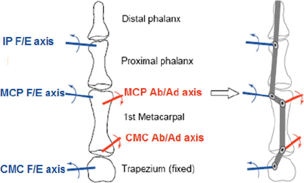
Motion of the thumb is generally described with 5 DOF [1, 13, 14, 27] arising from the carpometacarpal (CMC), metacarpophalangeal (MCP) and interphalangeal (IP) joints. The 5 DOF have been modeled by: flexion/extension (F/E) followed by abduction/adduction (Ab/Ad) of the CMC joint; Ab/Ad followed by F/E of the MCP joint; and F/E of the IP joint (Fig. 1). The axes of rotation for these DOF, however, are thought to be non-orthogonal and non-intersecting [1, 13, 14]. Indeed, these features are crucial to thumb functionality as they produce the axial rotation which enables opposition of the thumb with the fingertips. The anatomy-based kinematic model of the thumb has been converted into a robotics-based description with the standard Denavit-Hartenberg (D-H) parameters in [27]; thus, it is possible to approximate thumb kinematics using an exoskeleton with hinged linkages.
Fig. 1.
A Virtual Five-link Model of the Thumb [27]
Unlike current exoskeleton designs, the ATX is designed to provide independent control of each of these DOF. Moreover, the axes of rotation mirror those of the thumb itself, thereby allowing natural movement of the thumb.
2.2 Joint Range of Motion
In physiological systems, joint rotation is limited. For the thumb, the range of permissible motion varies across the DOF. Table 1 lists comparative data from three different researchers, quantifying the range of motion in the different thumb joints. It should be noted that the ranges reported in Table 1 can vary considerably from one study to another. These differences may arise from the geometry of the thumbs tested, or variations in measurement methods. In the ATX design, the goal is to maximize the potential thumb workspace inside the exoskeleton by enabling ranges of motion similar to those listed in Table 1.
Table 1.
Thumb Joint Range of Motion (Unit: Degree)
2.3 Joint Velocity Capacity
Angular velocity of the thumb tip can exceed 1000°/s [31]. Accordingly, in our design we sought to achieve this thumb-tip velocity of 1000°/s. The capability to produce high speed motion is necessary for the application to practical thumb manipulation tasks and to the study of power deficits. Indeed, it has been shown in the fingers that relative torque deficits may increase at higher rotational velocities [32].
2.4 Joint Torque Capacity
A recent study assessed the maximum thumb-tip forces of stroke survivors with severe or moderate hand impairment and in age-matched subjects with no neurological deficits [6]. The maximum active isometric thumb-tip forces that could be produced were recorded for each of 6 intended directions: distal, proximal, adduction, abduction, flexion, extension. Using one of the Denavit-Hartenberg (D-H) parameter sets proposed for the thumb [27], we converted the isometric thumb-tip forces into corresponding joint torques.
Table 2 shows the computed maximum torque of each joint across all subject groups.
Table 2.
Maximum Joint Torques of the Thumb (Unit: N-m)
| Thumb Joint | Subjects | ||
|---|---|---|---|
| Control | Stroke - Moderate | Stroke - Severe | |
| CMC F/E | 5.59 | 2.66 | 0.99 |
| CMC Ab/Ad | −4.81 | −2.40 | −0.91 |
| MCP F/E | 3.67 | 1.54 | 0.94 |
| MCP Ab/Ad | −3.09 | −1.78 | −0.85 |
| IP F/E | 1.85 | 0.58 | 0.48 |
To accommodate the majority of our target population, moderately impaired stroke survivors, we chose the peak joint torque outputs of the exoskeleton to be comparable to those measured in stroke survivors with moderate hand impairment, i.e., 2.5 N-m at CMC F/E, 2 N-m at Ab/Ad joints, 1.5 N-m at MCP F/E and Ab/Ad joints, and 0.5 N-m at IP F/E joint.
3 The ATX Design
3.1 Mechanical Design
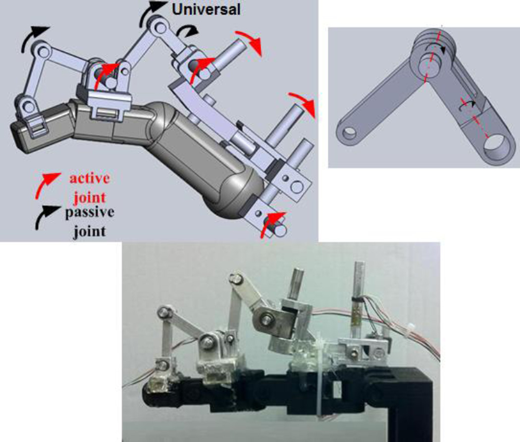
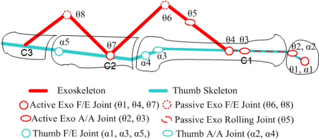
In order to achieve independent actuation of each thumb joint, the ATX has 5 active DOF and 3 passive DOF. The five active joints produce F/E of the CMC, MCP and IP joints, and Ab/Ad of the CMC and MCP joints (Fig. 2). The exoskeleton physically attaches to the distal and proximal segments of the thumb via Velcro straps. A cable wrapped about the MCP joint helps to secure the ATX to the metacarpal segment. The two proximal joints of the ATX are aligned with the F/E and Ab/Ad of the CMC joint (Fig. 2). For these two joints, we assume static centers of rotation, as is commonly accepted in similar instances [23, 33]. The attachment points which actuate the MCP and IP joints are connected through two-bar linkages, which accommodate the variation in segment lengths across the population and rely on the users’ natural joint center of rotation. The lengths of linkages for each joint are calculated according to the thumb size reported in literature [27]. To fit a broad range of thumb sizes, two sets of interchangeable linkages are designed for long and short thumbs. Velcro straps connect the exoskeleton to the distal and proximal thumb segments (Fig. 3). A cable wrapped around the thumb between the webbing and the proximal side of the metacarpophalangeal joint secures the device to the metacarpal segment.
Fig. 2.
The SolidWorks model (top left); the universal joint (Top Right) for axial rotation between MCP and CMC; the ATX attached on an artificial thumb (bottom). Flexible shafts are hidden for clarity.
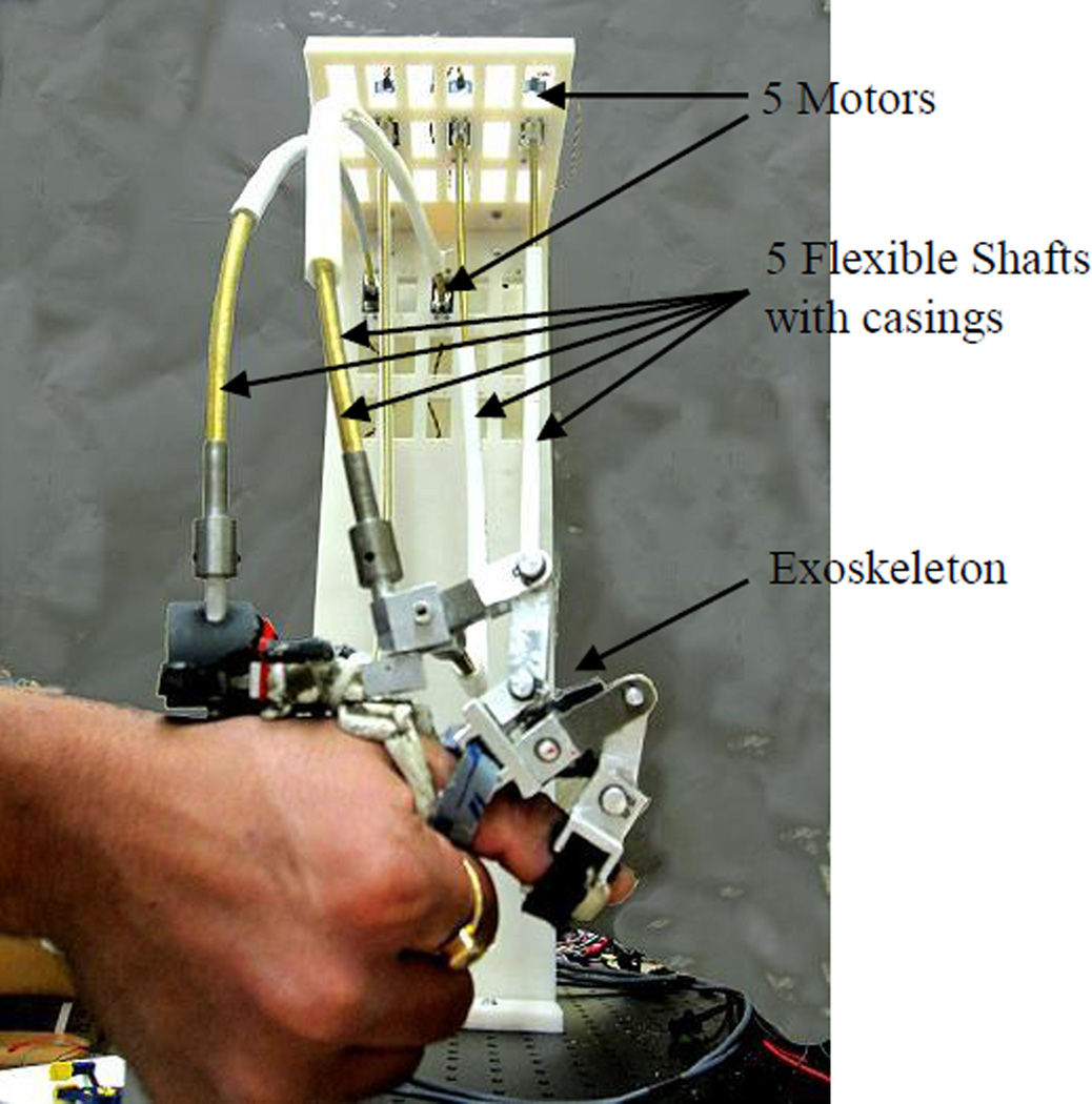
Fig. 3.
The ATX attached on the human thumb by Velcro straps. The motors are placed remotely and connected to the ATX by flexible shafts.
As mentioned earlier, an axial rotation will be observed between the metacarpal and proximal segments when MCP Ab/Ad occurs. This motion is important for thumb opposition. Thus a universal joint, which has 2 passive DOF, is included in the exoskeleton to allow this axial rotation (Fig. 2). The total mass of the exoskeleton without the flexible shaft transmission system is less than 250 grams. Most of the components were fabricated from aluminum alloy, with only the exoskeleton shafts made of steel. The weight of the flexible shafts is partially supported by the thumb, with the magnitude dependent upon thumb position and posture in space.
3.2 Actuation System
The ATX is actuated by DC motors (AKM Series Motor, Kollmorgen, Munkekullen, Sweden), with one motor controlling each joint. To minimize the weight of the exoskeleton carried by the user, the motors are located remotely from the thumb exoskeleton and supported by an external platform. This is made possible by the use of flexible shafts to transmit motor torque to the ATX. The flexible shaft, which is coupled with both the motor shaft and the driving shaft on the ATX joint (Fig. 3), transmits rotary motion between the motors and the exoskeleton while allowing flexibility in its shape between its two ends. By changing shape, the flexible shaft can accommodate variations in distance between the motor and the exoskeleton as the digit moves; thus, the motors can remain stationary even as the corresponding shafts on the exoskeleton move. The flexibility of the shafts also improves backdrivability of the system. Unlike cable transmission, for which two cables (and thus typically two motors) are needed to transmit torque in both the clockwise and counter-clockwise directions, the flexible shaft provides solid coupling between the motor shaft and the driving shaft of the ATX; it can rotate the joint in either a clockwise or counter-clockwise direction so that only one motor is needed for each DOF. To maximize backdrivability, the motor for IP joint has no gearing and motors for the CMC and MCP joints have only a 3:1 gearing ratio.
3.3 Sensors
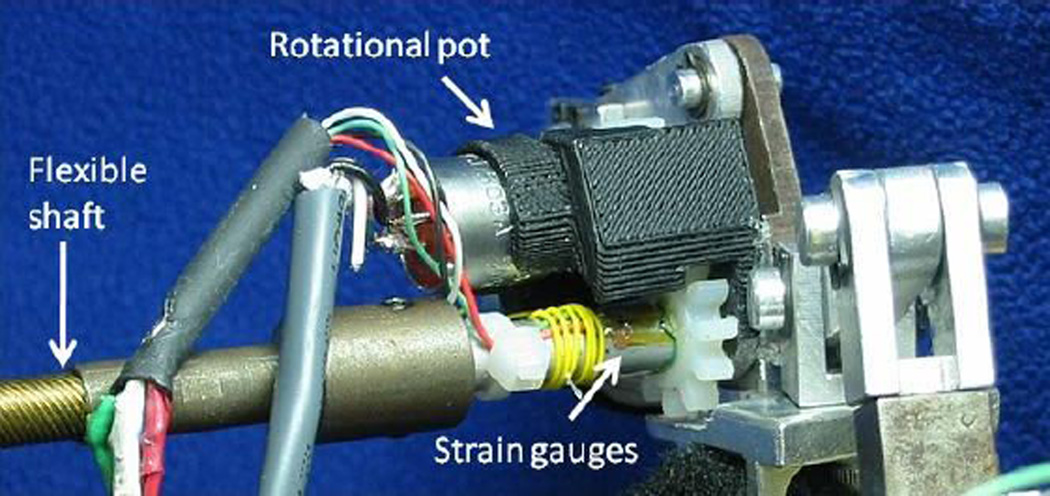
To control thumb manipulation tasks, the ATX must support both position and torque control at each joint. Thus, both joint angle and torque measurements are required for feedback control and for data collection. Each of the motors have integrated encoders, however, due to the flexible shaft transmission, the values measured at the motor shafts and the ATX shafts may deviate. Instead, the joint angles of the exoskeleton are measured directly at the joints with potentiometers (Precision Electronics Corp., Toronto, Canada) affixed to the shafts of the ATX with gear sets (Fig. 4). The joint angles of the thumb can be calculated by the joint angles of the ATX through kinematic equations.
Fig. 4.
Potentiometer and strain gages on one ATX joint with flexible shaft connected
Joint torque is measured through full-bridge strain gages attached on the cylindrical driving shafts of the ATX (Fig. 4). Namely, two rosettes of strain gauges are attached (one in front and on in back) of each cylindrical drive shaft and these gauges are then incorporated into a Wheatstone bridge. The full-bridge strain gage circuit is able to eliminate nonlinearity and hysteresis in the torque measurement.
The angle measurements from the potentiometers and torque measurements from the strain gages were calibrated in our experiments and showed high linearity.
3.4 The Real-time Control System
The angular position and torque signals are used to implement low-level feedback control of each joint. Depending on the application, either position control or force control may be required. All control programs are developed in MATLAB Simulink. The real-time control of the thumb exoskeleton is implemented using MATLAB xPC Target software [34].
A PCI-6229 ADC board (National Instruments, Austin, TX) installed on the target PC performs analog-digital conversion of torque sensor signals and potentiometer signals. A CNT32-8M encoder board (CONTEC, Sunnyvale, CA) records quadrature encoder signals and a PCIM-DDA06/16 DAC board (Measurement Computing, Norton, MA) converts digital command signals into the analog signals which drive the S200 motor amplifiers (Kollmorgen, Munkekullen, Sweden). All signals are sampled at 1 kHz.
3.5 Safety and Limitations
A number of safety mechanisms are present to ensure safe interaction with the individual’s hand. The lever linkages restrict the angular position of each joint of the ATX to remain within the physiologically acceptable range. An emergency kill switch is provided to immediately disable all motors. Software monitoring of both joint position and motor torque continuously checks to see if specified limits are exceeded and immediately disables the system if this occurs. To avoid excessive overshoot, gains of the position and torque controllers are tuned to achieve over-damped or critically damped response.
In our design, individually sized motors and flexible shafts are selected for the different joints. In this manner, peak motor torque is matched to peak voluntary subject torque and thus the potential for excessive torque is minimized.
4 Kinematic Analysis
Both the ATX and the thumb have multiple DOFs. The motion compatibility and determinism need to be addressed to ensure safety and functionality. Motion compatibility describes the extent to which the thumb can move naturally while attached to the ATX. Motion determinism refers to the capability to the ATX to control the thumb. The kinematics of the coupled system of the ATX and the thumb is analyzed in this section to address these issues.
The thumb and the ATX can be modeled as chains of rigid links (Fig. 5). Both the thumb and the ATX models have individual kinematic redundancy for the 3 DOF of their tip locations, as the thumb model has 5 DOF and the ATX has 5 active DOF and 3 passive DOF in the joint-space (orientation of the end-effectors is not considered for the current analysis). Thus, for a given task-space trajectory, there will be an infinite number of possible joint-space trajectories for either the thumb or the ATX model. One concern of this redundant system is whether a unique mapping can be established between the joint-space trajectories of the thumb and the ATX models.
Fig. 5.
The thumb and the linkage ATX models
The task-space trajectories of the thumb model and the ATX model are represented by the joint-space trajectories using forward kinematics:
| (1) |
where X⃑thumb, X⃑exo ∈ ℜ3*1 are the thumb-tip position and the end-effector position of the ATX model in the Cartesian space, respectively. α⃗ ∈ ℜ5*1 is the vector of the joint angles of the thumb model; θ⃗a ∈ ℜ5*1, a=1, 2, 3, 4 and 5, and θ⃗p ∈ ℜ3*1, p=6, 7 and 8, are the vectors of the active and the passive joint angles of the ATX model, respectively.
The position vectors of the attachment points between the thumb and exoskeleton at the metacarpal (C1), proximal (C2) and distal phalanges (C3), can be written as X⃑C1, X⃑C2 and X⃑C3 respectively,
| (2) |
and,
| (3) |
where F⃑1, G⃑1 ∈ ℜ2*1, F⃑2, F⃑3, G⃑2, G⃑3 ∈ ℜ3*1 are the functions of the positions at constraint points.
Since functions F⃗(θ⃗a, θ⃗p) =[F⃑1;F⃑2;F⃑3] and G⃗(α⃗) = [G⃑1;G⃑2;G⃑3] represent positions of the same set of constraint points,
| (4) |
It is unrealistic to solve Equation (4) analytically to obtain the joint angle of the thumb from the measured joint angle of the ATX directly as those equations are highly nonlinear. Thus, Equation (4) is differentiated once to obtain the mapping at the velocity level,
| (5) |
| (6) |
Let
where Jdep ∈ ℜ8*8, Jθa ∈ ℜ8*5. Equation (6) can be rewritten as
| (7) |
where J1 = −(Jdep)−1 Jθa, J1 ∈ ℜ8*5.
Equation (7) gives the relationship of angular velocities between active joints of the ATX and respective thumb joints, and between active joints and passive joints within the ATX. Note that the coupled system of the thumb model and the ATX model has a total of 13 DOF in the joint-space and Equation (7) introduces 8 constraint equations, thus, once joint-space trajectories of active joints of the ATX model (5 DOF) are defined, corresponding joint-space trajectories for the thumb model will be determined by Equation (7). Similarly, once joint-space trajectories of the thumb model are defined, corresponding joint-space trajectories of the ATX model will also be determined. Thus, a unique mapping can be achieved between joint-space trajectories of the thumb model and the ATX model, thereby indicating that the coupled system of the ATX and the thumb is deterministic. Details of the kinematic analysis can be found at [35].
5 Flexible Shaft Transmission Testing
In our design, the transmission through the flexible shafts allows actuators to be placed remotely from the ATX. As flexible shafts have not been used in robot-assisted rehabilitation systems before, our major concern is the transmission loss of both motion and torque. Preliminary tests were conducted to investigate the transmission performance of the flexible shaft. The flexible shaft was bent with a 90° curvature in the tests; this amount of bend yielded the best torque transmission in preliminary trials. The ATX uses the same curvature.
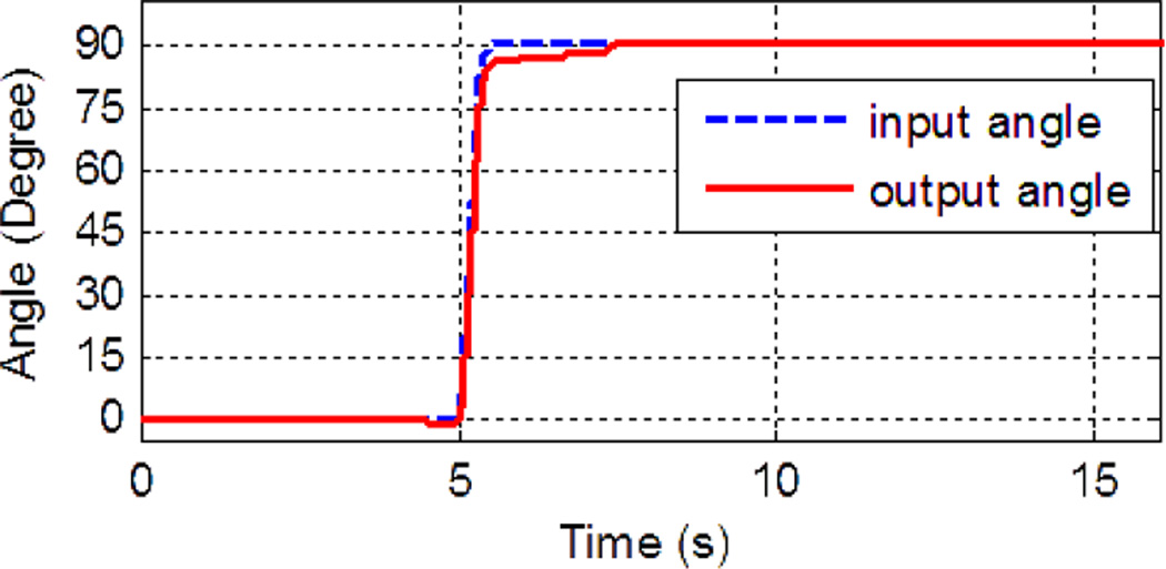
First, we analyzed the motion transmission performance by measuring joint angles at one end of the shaft and the other end of the shaft (Fig. 6). When external resistance was imposed, output rotation produced by the flexible shaft was less than the angular displacement put into the shaft in the open-loop tests. Some of the input produced twisting, or “helixing”, in the shaft rather than rotation at the other end. Thus, in closed-loop control, the angular position measurements have to be measured directly at the exoskeleton end rather than at the motor end. The tendency to helix can be mitigated by placing an outer casing around the shaft (Fig. 3). Rotation of the exoskeleton shaft is measured directly with the potentiometer to enable closed-loop control.
Fig. 6.
Motion transmission through flexible shaft: input and output rotation angles at two ends of flexible shaft are shown.
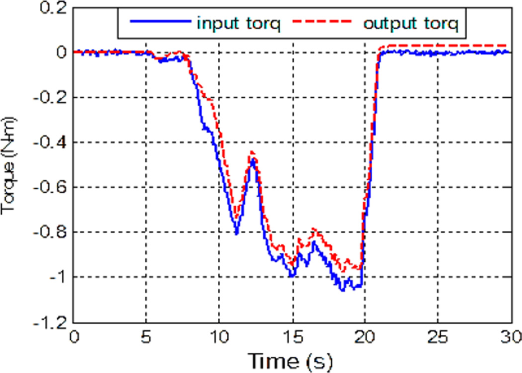
Torque transmission performance through the flexible shaft was examined as well. The output torque at the distal end of the shaft stayed within 10% error of the input torque imposed at the proximal end of the shaft for input torque up to 1 N-m (Fig. 7). At higher torque input, which may be required in thumb rehabilitation and motor control study, greater deviation was observed. Thus, joint torque is measured directly in the driving shaft of the ATX, rather than at the motor, to enable closed-loop control.
Fig. 7.
Motion transmission through flexible shaft: input and output torques at the two ends of flexible shaft are shown.
6 Performance Testing and Experimental Results
In this section, we present the results of the experiments conducted to measure the allowable thumb workspace after donning the ATX and to test the kinematic and kinetic performance of the ATX. For readability, we use the terms J1, J2, J3, J4 and J5 to represent the ATX joints corresponding to the following anatomical DOF: CMC F/E, CMC Ab/Ad, MCP F/E, MCP Ab/Ad and IP F/E.
6.1 Allowable Thumb Workspace Test
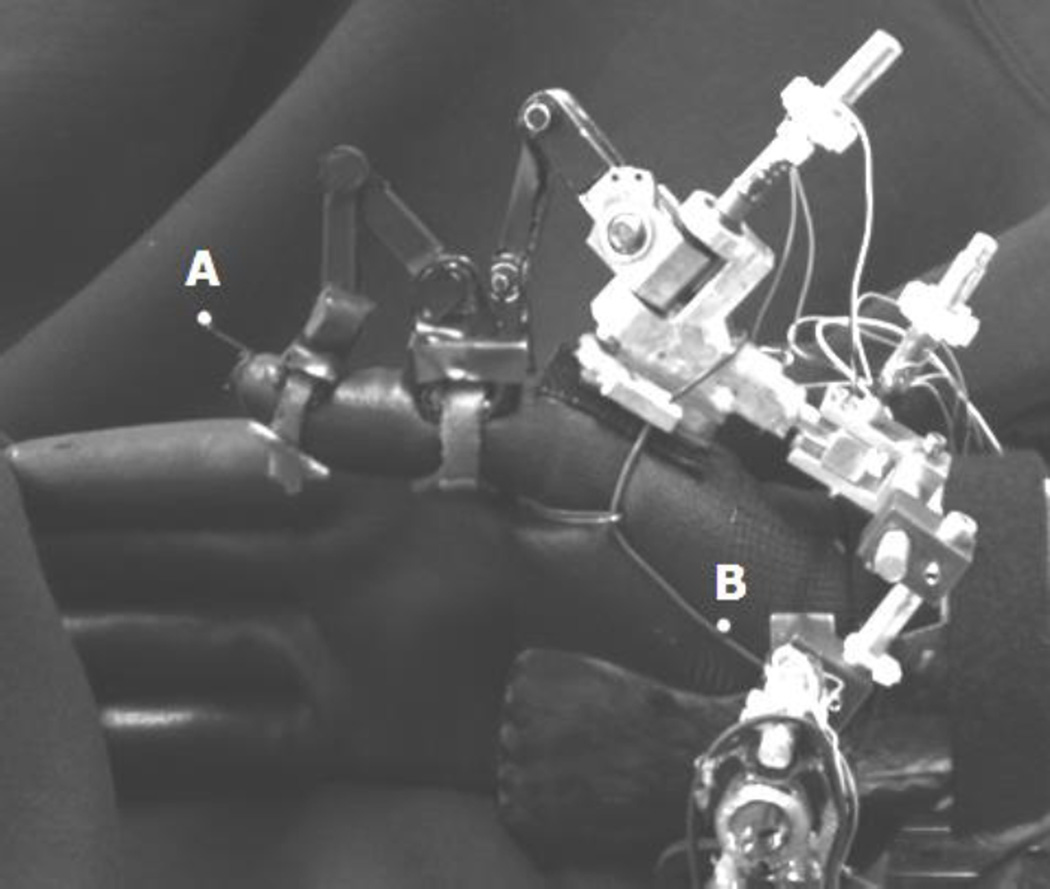
The ATX workspace was measured in 3 subjects. During the experiment, each subject was asked to perform 4 sets of movements: full thumb extension to full thumb flexion, full thumb adduction to full thumb abduction, and random motion of the thumb at upper available workspace (thumb up) and lower available space (thumb down). The experiment was executed by each subject with (ATX condition) and without (free movement condition) the ATX. For both conditions, the motions of the thumb tip and reference markers were recorded by Digital Motion Analysis and Motion Capture System (Spica Technologies Corporation, Maui, Hawaii) with average calibration error 0.68 mm.
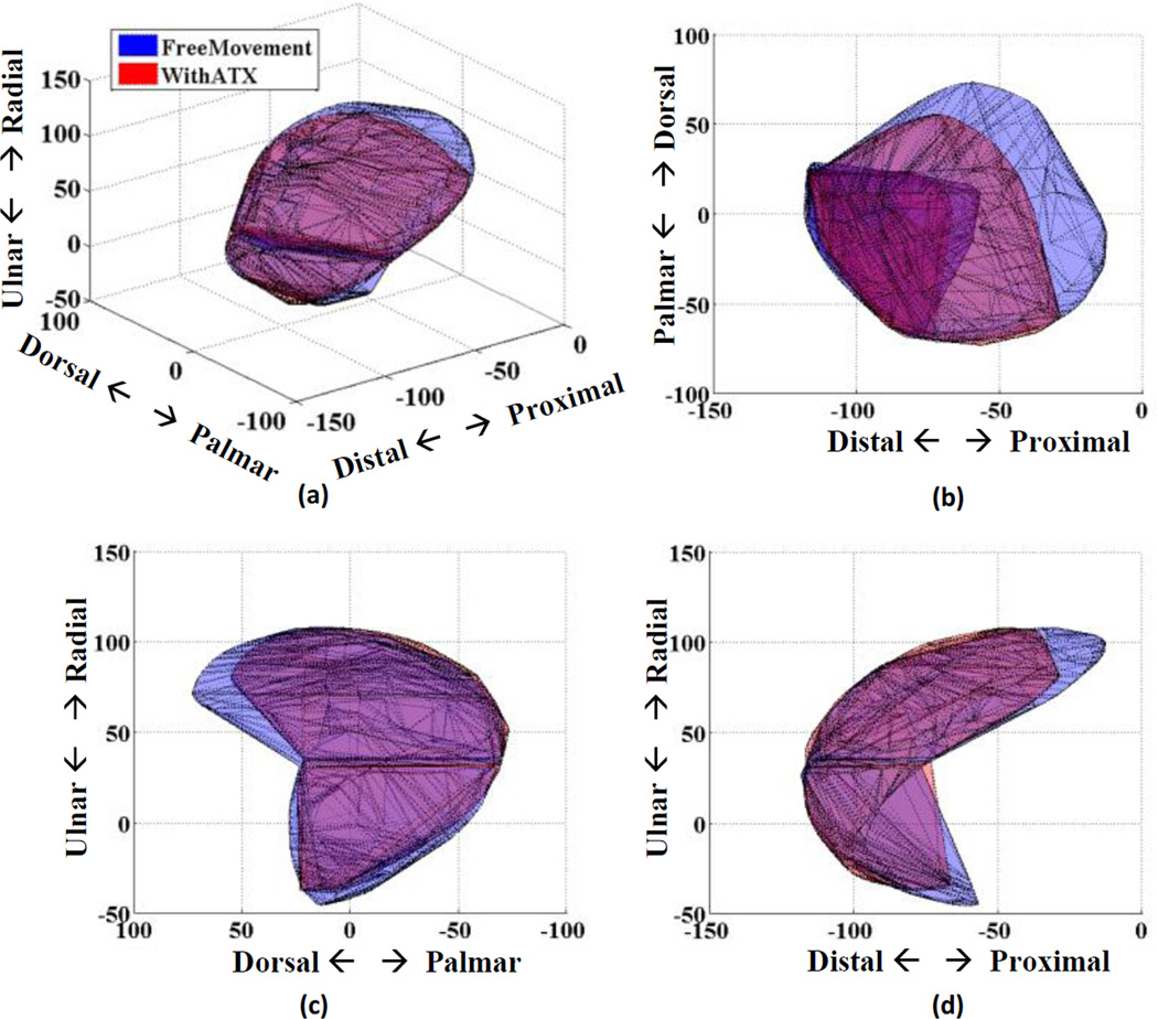
ATX and free movement workspaces were computed from optical marker measurements (Fig. 9). These workspaces were divided into upper (thumb extension) and lower regions (thumb flexion) by the ulnar/radial plane. Volumes of upper and lower spaces were computed to represent the workspace volume for both the ATX on and free movement trials.
Fig. 9.
ATX workspace representation from subject 3. Free movement workspace is the blue area, while workspace with ATX is in red. (a) 3D view; (b) top view; (c) frontal view; (d) lateral view.
From Fig. 9 it is clear that the thumb with and without the exoskeleton overlap on a majority of the workspace although the ATX does not reach a small region in the outmost proximal-radial hyperextension volume. The mean complete workspace volume ratio of ATX to free movement is 79% across three subjects, while for lower part workspace volume ratio is 94%, where most of volume overlaps with each other as shown in Fig. 9. Note that the lower portion of the thumb workspace is reported as the more functional workspace in the entire workspace of the thumb [36]. All subjects reported they felt comfortable in ATX movement experiments.
6.2 Kinematic Performance Test
Experiments were conducted to perform closed-loop joint position control with PI controllers on an artificial thumb (Fig. 2). This artificial thumb, fabricated using a 3D printer, has a comparable size to a medium-sized human thumb with 5 DOF, corresponding to the human thumb DOF. For testing purposes, the axes of rotation of the artificial thumb are orthogonal. The feedback signal to the PI controller was the joint angle of the thumb as computed from the joint angle of the ATX, as measured by potentiometers at the ATX joints.
6.2.1 Ramp Trajectory Tracking
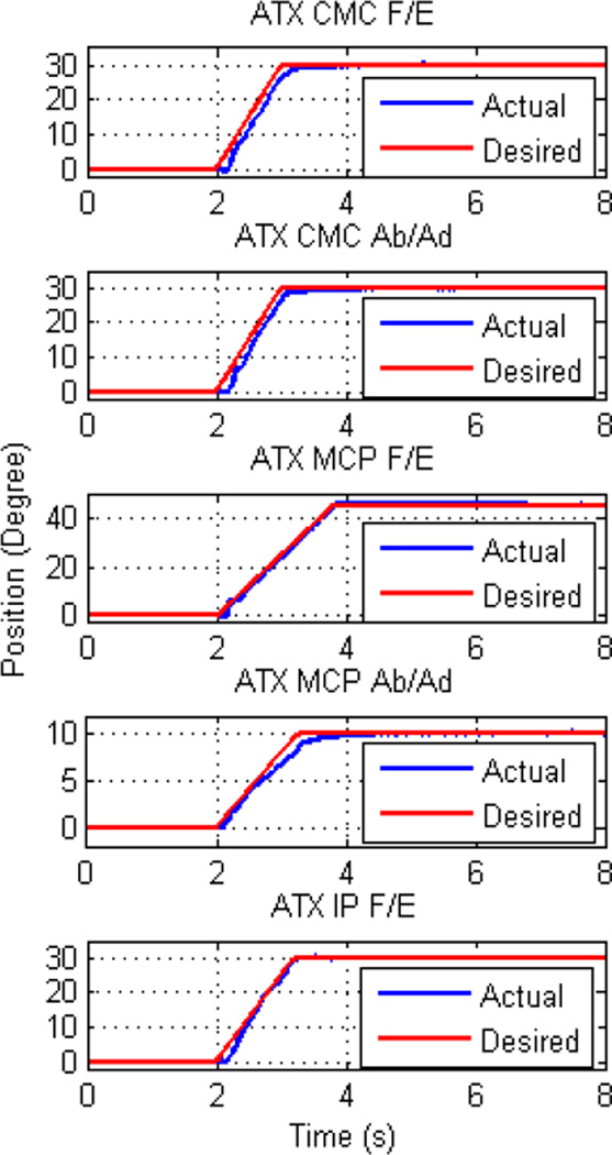
The first experiment was to examine the ability of the ATX to track a ramp trajectory at each joint. One joint was tested at a time. The experimental results of all 5 joints are shown in Fig. 10. The root mean square (RMS) errors at steady state were 0.098°, 0.105°, 0.124°, 0.118° and 0.140° from J1 to J5, respectively.
Fig. 10.
Tracking of ramp trajectory for individual joint. Each joint was tested separately in different trials.
6.2.2 Velocity Capacity Testing
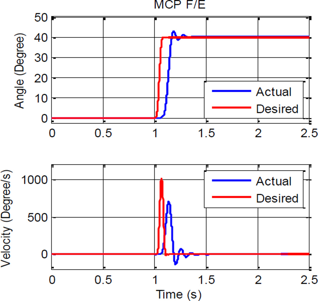
The second experiment was to examine the capability of the ATX to provide high instant velocity at each joint. A desired smooth trajectory was created for each joint in order to achieve an instant velocity of 1000°/s for the thumb tip. Motion of one joint was tested at a time. Fig. 11 shows an example of the position and velocity trajectories of the J3 joint. The maximum velocities observed in the experiment were 450°/s, 550°/s, 650°/s, 520°/s and 900°/s from J1 to J5, respectively. Note that the design specification was to achieve 1000°/s at the tip of the thumb (i.e., not in each joint) and as such the above individual joint velocities together allows achieving the target tip velocity.
Fig. 11.
Tracking of trajectory with high instant speed at MCP F/E joint
6.2.3 Multiple Joint Position Control
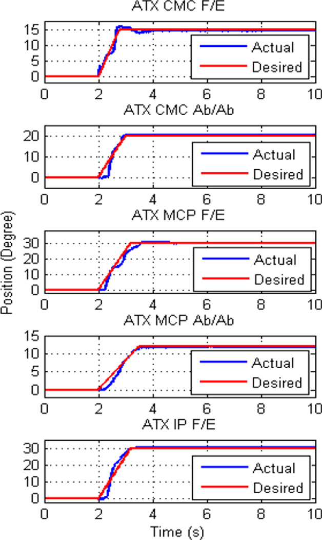
All 5 joints of the ATX were controlled to track different ramp trajectories simultaneously. The starting configuration of the ATX was at 0° for all 5 joints and the final configuration was at (15°, 20°, 30°, 12°, 30°) joint angles from J1 to J5. The experimental results are shown in Fig. 12. The RMS errors at steady state were 0.110°, 0.298° 0.303°, 0.114° and 0.148° from J1 to J5, respectively.
Fig. 12.
Control of all 5 joints from one configuration to another
6.3 Kinetic Performance Testing
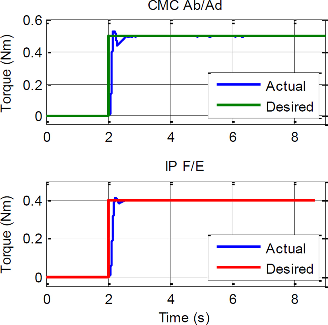
Joint torque control performances for all joints were also evaluated in experiments. Fig. 13 shows the experimental results for J2 and J5 joints as examples. The desired torque was 0.5 N-m for J2 and 0.4 N-m for J5. The errors at steady state for all 5 joints were minimal (under 0.008 Nm).
Fig. 13.
Experimental results for individual joint torque control
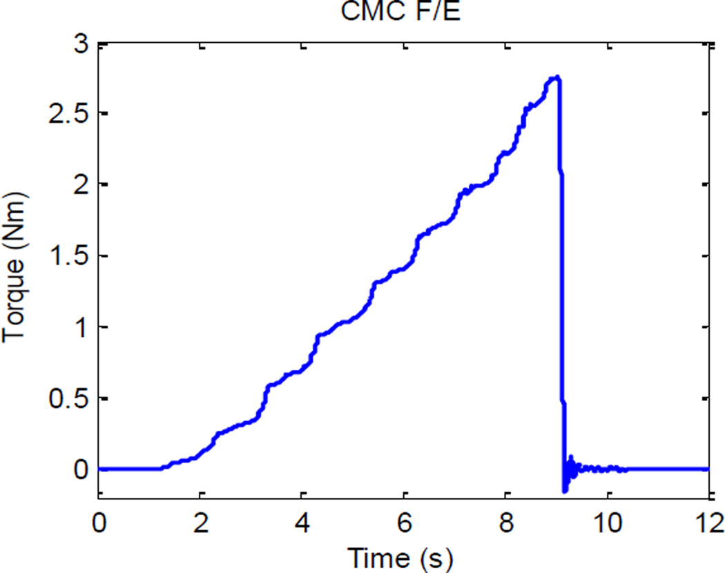
The torque capacity was tested in an open loop experiment. The output command to the motor was gradually increased and the torque applied on the CMC F/E joint of the ATX was recorded by the strain gages. The torque trajectory is shown in Fig. 14. It should be noted that to prevent excessive helixing of the flexible shaft, which would severely degrade the transmission performance and produce off-axis force/torque, the maximum torque allowed by the current flexible shaft is limited to 2.5 N-m in the closed loop control algorithm.
Fig. 14.
Torque capacity testing at CMC F/E joint
7 Discussion
In this work, we present the design and validation testing of an actuated thumb exoskeleton, the ATX, capable of examining motor control of the thumb and of implementing and evaluating rehabilitation paradigms for thumb movement. In order to achieve those goals, the exoskeleton is designed to be able to independently control each DOF of the thumb with sufficient power and speed. To our knowledge, no current exoskeleton possesses all of these capabilities.
The prototype ATX is able to produce natural motion for the thumb, with minimal restriction to thumb movement. The 5 joints of the ATX are designed to correspond with the non-orthogonal and non-intersecting rotational axes of the 5 DOF of the thumb [1, 13, 14, 27]. In our preliminary test, the joint range of motion allowed by the ATX translates into almost 80% of the natural thumb workspace. Importantly, the coverage in the more functionally relevant lower region reached 94% across the subjects [36]. Losses predominantly occurred for workspace regions requiring IP hyperextension. All subjects reported they felt comfortable while moving these thumb with the ATX on. The available workspace could be expanded even further by increasing the varieties of interchangeable exoskeleton linkages with different lengths.
DC motors were chosen to actuate the ATX due to their high torque and velocity performance in all four quadrants of the torque-velocity space. To reduce the load on the user’s thumb, the motors are located remotely from the thumb exoskeleton, and supported by an external platform. This is made possible by the use of flexible shafts to transmit motor torque to the ATX. The flexible shaft is sufficiently rigid to transmit rotary motion between the motors and the exoskeleton while still being sufficiently compliant to change shape to accommodate variations in distance between the motor and the exoskeleton as the digit moves. The flexible shaft can rotate the joint in either clockwise or counter-clockwise direction, thus, only one motor is needed for each DOF. In comparison, cable transmission generally requires two motors to actuate one DOF as the cable can only provide pulling force. Cable actuation is also challenging due to the high DOF and compact size of human thumb. In conjunction with these beneficial features, the flexible shafts do have other features which can make them challenging to use. Transmission of motion can be adversely affected when the resistance is high. While transmission loss in motion was not observed under low torque, it was noticeable when the torque load exceeded 0.5 N-m. The flexible shaft would start to helix when transmitted torque exceeds the torque limit. Thus, the joint position and joint torque must be measured directly at the output end of the flexible shaft, the ATX joint, to provide accurate feedback for control purpose. For the ATX, potentiometers and strain gages are used to measure the angle and torque, respectively, directly at ATX joints.
These issues are overcome, however, through the use of feedback control and torque/position measurement directly at the thumb. We examined the kinematic performance of the ATX under feedback control in a variety of experiments. These included the tracking of ramp trajectories, trajectory with high instantaneous velocity at an individual joint, and tracking of different ramp trajectories for multiple joints simultaneously.
The tracking of ramp trajectories for individual joints was accurate for all 5 joints. The RMS error at steady state was under 0.3° for each joint. As human perception of movement requires a minimum 1° displacement [37], this accuracy is satisfactory. Due to the nature of flexible shaft transmission, response delays in the experiments ranging from 0.08 to 0.2 second were observed. These delays were resulted from initial winding of coils in the flexible shafts, as well as from static friction. Feedforward compensation (preloading) can be implemented in the controller to reduce the response delay in future applications for which a faster response is required.
The speed capacity of each joint was tested by tracking trajectories with high instantaneous velocity. The maximum velocities observed were 450°/s, 550°/s, 650°/s, 520°/s and 900°/s from J1 to J5, respectively. These joint velocities together will be sufficient to produce the angular velocity at the thumb tip at the level of 1000°/s, which meets our design requirement.
In the next experiment, all 5 joints were controlled simultaneously to track different ramp trajectories. The results show that the ATX can provide accurate independent actuation concurrently at each joint.
The kinetic performance of the ATX was also examined in our experiments. All 5 joints were able to produce the desired torque accurately. The torque capacity tested at CMC F/E joint showed that the ATX was capable of producing 2.5 N-m of torque. Since the other joints need less torque than the CMC F/E joint, the torque capacity of the ATX meets our design target.
Although conducted on an artificial thumb, the kinematic and kinetic experimental results verify the novel capabilities of this exoskeleton under benchmark testing. The artificial thumb designed for the experiments has the size and DOFs of a medium-sized human thumb. From the experimental results and analysis, we believe that the ATX presented in this work is able to provide controlled independent actuation to each thumb joint with high speed and torque capacities. These capabilities, which exceed existing exoskeletons in power, speed and actuated DOF, will permit careful evaluation of the motor control of stroke survivors and of different rehabilitation strategies. For example, the high achievable speeds and power will permit assessment of spasticity [38] and isokinetic strength and power [32]. The large torque capabilities and individual actuation of each DOF will be able to overcome the coactivation in the affected thumb and permit evaluation of peak strength.
8 Conclusion and Future Work
This work presents the design and performance testing of an actuated thumb exoskeleton (ATX) that permits independent bi-directional actuation in each of the 5 DOF of the thumb using a mechanism that has 5 active DOF and 3 passive DOF. The transmission system using flexible shafts is able to transmit considerable joint torque and speed to the user while still allowing natural movement of the thumb. Independent control of each thumb joint with high speed and torque capacities are important criteria in designing a general platform to evaluate thumb rehabilitation therapies and motor learning paradigms and have yet to be implemented in existing thumb exoskeletons. Experiments of closed-loop position and torque control were conducted and the results showed that both the position and torque control performance was satisfying.
In future work, we will implement different rehabilitation strategies on the ATX, e.g., low-impedance, force perturbation, and assist-as-needed strategies. A high-level supervisory controller will be developed to coordinate these rehabilitation strategies. Further, the ATX will be coupled with an actuated finger exoskeleton (AFX) [39] that we have developed for the index finger to implement rehabilitation strategies in restoring control of pinch movements following stroke.
Fig. 8.
Subject wearing ATX with two optical markers to determine available thumb workspace. (A) Thumb tip marker; (B) Wrist reference marker.
References
- 1.Giurintano DJ, Hollister AM, Buford WL, Thompson DE, Myers LM. A virtual five-link model of the thumb. Med Eng Phys. 1995 Jun;17:297–303. doi: 10.1016/1350-4533(95)90855-6. [DOI] [PubMed] [Google Scholar]
- 2.Penfield W RT. The cerebral cortex of man: a clinical study of localization of function. New York: Macmillan; 1950. [Google Scholar]
- 3.Nakamura K, Sakai K, Hikosaka O. Neuronal activity in medial frontal cortex during learning of sequential procedures. J Neurophysiol. 1998 Nov;80:2671–2687. doi: 10.1152/jn.1998.80.5.2671. [DOI] [PubMed] [Google Scholar]
- 4.Gandevia SC, Refshauge KM, Collins DF. Proprioception: peripheral inputs and perceptual interactions. Adv Exp Med Biol. 2002;508:61–68. doi: 10.1007/978-1-4615-0713-0_8. [DOI] [PubMed] [Google Scholar]
- 5.Häger-Ross C, Schieber MH. Quantifying the independence of human finger movements: comparisons of digits, hands, and movement frequencies. J Neurosci. 2000 Nov;20:8542–8550. doi: 10.1523/JNEUROSCI.20-22-08542.2000. [DOI] [PMC free article] [PubMed] [Google Scholar]
- 6.Triandafilou KM, Fischer HC, Towles JD, Kamper DG, Rymer WZ. Diminished capacity to modulate motor activation patterns according to task contributes to thumb deficits following stroke. J Neurophysiol. 2011 Oct;106:1644–1651. doi: 10.1152/jn.00936.2010. [DOI] [PubMed] [Google Scholar]
- 7.Colditz JC. Anatomic considerations for splinting the thumb. In: M. E. J. Hunter JM, Callahan AD, editors. Rehabilitation of the hand: surgery and therapy. Philadelphia: C. V. Mosby Company; [Google Scholar]
- 8.AH Association. Heart and Stroke Statistical Update. 2010 Available: http://www.Americanheart.org/statistics/stroke.htm. [Google Scholar]
- 9.Bonita R, Stewart A, Beaglehole R. International trends in stroke mortality: 1970–1985. Stroke. 1990 Jul;21:989–992. doi: 10.1161/01.str.21.7.989. [DOI] [PubMed] [Google Scholar]
- 10.Broderick J, Phillips S, Whisnant J, O'Fallon W, Bergstralh E. Incidence rates of stroke in the eighties: the end of the decline in stroke? Stroke. 1989 May;20:577–582. doi: 10.1161/01.str.20.5.577. [DOI] [PubMed] [Google Scholar]
- 11.Trombly C. Occupational therapy for physical dysfunction. Baltimore, MD: Williams & Wilkins; 1989. Stroke. [Google Scholar]
- 12.Lang CE, DeJong SL, Beebe JA. Recovery of thumb and finger extension and its relation to grasp performance after stroke. J Neurophysiol. 2009 Jul;102:451–459. doi: 10.1152/jn.91310.2008. [DOI] [PMC free article] [PubMed] [Google Scholar]
- 13.Hollister A, Buford WL, Myers LM, Giurintano DJ, Novick A. The axes of rotation of the thumb carpometacarpal joint. J Orthop Res. 1992 May;10:454–460. doi: 10.1002/jor.1100100319. [DOI] [PubMed] [Google Scholar]
- 14.Hollister A, Giurintano DJ, Buford WL, Myers LM, Novick A. The axes of rotation of the thumb interphalangeal and metacarpophalangeal joints. Clin Orthop Relat Res. 1995 Nov;:188–193. [PubMed] [Google Scholar]
- 15.Towles JD, Kamper DG, Rymer WZ. Lack of hypertonia in thumb muscles after stroke. J Neurophysiol. 2010 Oct;104:2139–2146. doi: 10.1152/jn.00423.2009. [DOI] [PMC free article] [PubMed] [Google Scholar]
- 16.Krebs H, Ferraro M, Buerger S, Newbery M, Makiyama A, Sandmann M, et al. Rehabilitation robotics: pilot trial of a spatial extension for MIT-Manus. J Neuroeng Rehabil. 2004 Oct;1:5. doi: 10.1186/1743-0003-1-5. [DOI] [PMC free article] [PubMed] [Google Scholar]
- 17.Kahn L, Zygman M, Rymer W, Reinkensmeyer D. Robot-assisted reaching exercise promotes arm movement recovery in chronic hemiparetic stroke: a randomized controlled pilot study. J Neuroeng Rehabil. 2006;3:12. doi: 10.1186/1743-0003-3-12. [DOI] [PMC free article] [PubMed] [Google Scholar]
- 18.Gijbels D, Lamers I, Kerkhofs L, Alders G, Knippenberg E, Feys P. The Armeo Spring as training tool to improve upper limb functionality in multiple sclerosis: a pilot study. J Neuroeng Rehabil. 2011;8:5. doi: 10.1186/1743-0003-8-5. [DOI] [PMC free article] [PubMed] [Google Scholar]
- 19.Nef T, Mihelj M, Riener R. ARMin: a robot for patient-cooperative arm therapy. Med Biol Eng Comput. 2007 Sep;45:887–900. doi: 10.1007/s11517-007-0226-6. [DOI] [PubMed] [Google Scholar]
- 20.Frisoli A, Bergamasco M, Carboncini MC, Rossi B. Robotic assisted rehabilitation in Virtual Reality with the L-EXOS. Stud Health Technol Inform. 2009;145:40–54. [PubMed] [Google Scholar]
- 21.Dovat L, Lambercy O, Gassert R, Maeder T, Milner T, Leong TC, et al. HandCARE: a cable-actuated rehabilitation system to train hand function after stroke. IEEE Trans Neural Syst Rehabil Eng. 2008 Dec;16:582–591. doi: 10.1109/TNSRE.2008.2010347. [DOI] [PubMed] [Google Scholar]
- 22.Takahashi C, Der-Yeghiaian L, Le V, Motiwala R, Cramer S. Robot-based hand motor therapy after stroke. Brain. 2008 Feb;131:425–437. doi: 10.1093/brain/awm311. [DOI] [PubMed] [Google Scholar]
- 23.Schabowsky CN, Godfrey SB, Holley RJ, Lum PS. Development and pilot testing of HEXORR: hand EXOskeleton rehabilitation robot. J Neuroeng Rehabil. 2010;7:36. doi: 10.1186/1743-0003-7-36. [DOI] [PMC free article] [PubMed] [Google Scholar]
- 24.Kawasaki H, Ito S, Ishigure Y, Nishimoto Y, Aoki T, Mouri T, et al. Development of a Hand Motion Assist Robot for Rehabilitation Therapy by Patient Self-Motion Control; Rehabilitation Robotics, ICORR 2007, IEEE 10th International Conference on; 2007. Jun 13–15, pp. 234–240. [DOI] [PubMed] [Google Scholar]
- 25.Patton JL, Stoykov ME, Kovic M, Mussa-Ivaldi FA. Evaluation of robotic training forces that either enhance or reduce error in chronic hemiparetic stroke survivors. Exp Brain Res. 2006 Jan;168:368–383. doi: 10.1007/s00221-005-0097-8. [DOI] [PubMed] [Google Scholar]
- 26.Saunders DH, Greig CA, Young A, Mead GE. Association of activity limitations and lower-limb explosive extensor power in ambulatory people with stroke. Arch Phys Med Rehabil. 2008 Apr;89:677–683. doi: 10.1016/j.apmr.2007.09.034. [DOI] [PubMed] [Google Scholar]
- 27.Santos VJ, Valero-Cuevas FJ. Reported anatomical variability naturally leads to multimodal distributions of Denavit-Hartenberg parameters for the human thumb. IEEE Trans Biomed Eng. 2006 Feb;53:155–163. doi: 10.1109/TBME.2005.862537. [DOI] [PubMed] [Google Scholar]
- 28.Cooney WP, Lucca MJ, Chao EY, Linscheid RL. The kinesiology of the thumb trapeziometacarpal joint. J Bone Joint Surg Am. 1981 Dec;63:1371–1381. [PubMed] [Google Scholar]
- 29.Buchholz B, Armstrong TJ. A kinematic model of the human hand to evaluate its prehensile capabilities. J Biomech. 1992 Feb;25:149–162. doi: 10.1016/0021-9290(92)90272-3. [DOI] [PubMed] [Google Scholar]
- 30.Katarincic JA. Thumb kinematics and their relevance to function. Hand Clin. 2001 May;17:169–174. [PubMed] [Google Scholar]
- 31.Gutnik B, Nash D, Ricacho N, Hudson G, Skirius J. Power of performance of the thumb adductor muscles: effect of laterality and gender. Medicina (Kaunas) 2006;42:653–660. [PubMed] [Google Scholar]
- 32.Conrad MO, Kamper DG. Isokinetic strength and power deficits in the hand following stroke. Clin Neurophysiol. 2011 Nov; doi: 10.1016/j.clinph.2011.10.004. [DOI] [PubMed] [Google Scholar]
- 33.Zhang X, Lee SW, Braido P. Determining finger segmental centers of rotation in flexion-extension based on surface marker measurement. J Biomech. 2003 Aug;36:1097–1102. doi: 10.1016/s0021-9290(03)00112-x. [DOI] [PubMed] [Google Scholar]
- 34.xPC target, editor. Mathworks. http://www.mathworks.com/help/toolbox/xpc. [Google Scholar]
- 35.Wang F. Design and control of robotic systems for upper extremity rehabilitation following stroke. 2011 Available: http://etd.library.vanderbilt.edu/available/etd-12012011-210745/ [Google Scholar]
- 36.Kuo LC, Chiu HY, Chang CW, Hsu HY, Sun YN. Functional workspace for precision manipulation between thumb and fingers in normal hands. J Electromyogr Kinesiol. 2009 Oct;19:829–839. doi: 10.1016/j.jelekin.2008.07.008. [DOI] [PubMed] [Google Scholar]
- 37.Gandevia SC, Hall LA, McCloskey DI, Potter EK. Proprioceptive sensation at the terminal joint of the middle finger. J Physiol. 1983 Feb;335:507–517. doi: 10.1113/jphysiol.1983.sp014547. [DOI] [PMC free article] [PubMed] [Google Scholar]
- 38.Kamper DG, Rymer WZ. Quantitative features of the stretch response of extrinsic finger muscles in hemiparetic stroke. Muscle Nerve. 2000 Jun;23:954–961. doi: 10.1002/(sici)1097-4598(200006)23:6<954::aid-mus17>3.0.co;2-0. [DOI] [PubMed] [Google Scholar]
- 39.Jones CL, Wang F, Morrison R, Sarkar N, Kamper DG. Design and Development of the Cable Actuated Finger Exoskeleton for Hand Rehabilitation Following Stroke. Mechatronics, IEEE/ASME Transactions on. 2012;PP:1–10. doi: 10.1109/TMECH.2012.2224359. [DOI] [PMC free article] [PubMed] [Google Scholar]


