Abstract
A model of muscle contraction is proposed, assuming loose coupling between power strokes and ATP hydrolysis of a myosin head. The energy borrowing mechanism is introduced in a cross-bridge cycle that borrows energy from the environment to cover the necessary energy for enthalpy production during sliding movement. Important premises for modeling are as follows: 1) the interaction area where a myosin head slides is supposed to be on an actin molecule; 2) the actomyosin complex is assumed to generate force F(θ), which slides the myosin head M* in the interaction area; 3) the direction of the force F(θ) varies in proportion to the load P; 4) the energy supplied by ATP hydrolysis is used to retain the myosin head in the high-energy state M*, and is not used for enthalpy production; 5) the myosin head enters a hydration state and dehydration state repeatedly during the cross-bridge cycle. The dehydrated myosin head recovers its hydrated state by hydration in the surrounding medium; 6) the energy source for work and heat production liberated by the AM* complex is of external origin. On the basis of these premises, the model adequately explains the experimental results observed at various levels in muscular samples: 1) twist in actin filaments observed in shortening muscle fibers; 2) the load-velocity relationship in single muscle fiber; 3) energy balance among enthalpy production, the borrowed energy and the energy supplied by ATP hydrolysis during muscle contraction. Force F(θ) acting on the myosin head is depicted.
Keywords: myosin ATPase, enthalpy production, molecular machinery, loose coupling, Hill’s Formulation
In muscle contraction, the interaction between a myosin head and an actin molecule composing an actin filament generates force1–3. Experiments in the 1990s that used in vitro motility assay systems revealed a long myosin step, i.e., many power strokes per hydrolysis of a single adenosine triphosphate (ATP) molecule4–6. Around the same time, twists in actin filaments sliding on myosin molecules or myosin tracks fixed on a glass surface7,8 were reported in in vitro motility assay systems. These results suggest that the myosin head slides on several actin molecules per ATP hydrolysis and the force acting at a cross-bridge contains torque components around the axis of the actin filament, while the direction of the force acting on a myosin head during muscle contraction was long assumed to be parallel to the axis of the actin filament1–3. On the basis of many power strokes per ATP hydrolysis, the biased Brownian movement model was proposed by Yanagida and his colleagues9. In their model, a myosin head slides on a potential slope along the actin filament given by the relative positional relationship between the binding site of the actin molecule and a myosin head. Cooperative actions of multiple myosin heads generate vector movement of the actin filament.
In this paper, a model of molecular behavior during a cross-bridge cycle is proposed on the basis of many power strokes per ATP hydrolysis. For modeling, we paid attention to twists in actin filaments observed in in vitro motility assay systems7,8. In addition, we gave much thought to the molecular mechanism that realizes energy balance in enthalpy production (work + heat) from a cross-bridge, the energy source that is converted into enthalpy production, and the energy supplied by ATP hydrolysis. The physical process with the potentiality of the other energy source for enthalpy production is also described. The characteristic property of the force generated at a cross-bridge is depicted. The symbols in the text are explained in the Appendix.
Outline of the model: Molecular mechanism suggested by energy borrowing model
A myosin head (M*) energized by ATP hydrolysis and an actin molecule (A) form an actomyosin complex (AM*). In the AM* complex, a potential valley is formed. Load P+ ρ acting on the myosin head in the AM* complex causes molecular distortions both of the myosin head and the actin molecule. Consequently, the potential valley changes its direction on the actin molecule, and AM* generates force F, which acts on the myosin head, which then slides in the interaction area of the actin molecule forced by force F.
The energy supplied by ATP hydrolysis is used to maintain the high-energy state of the myosin head M*. The high-energy state of the myosin head M* is composed of two states reversibly transformed by interaction with the actin filament and the environment, and the myosin head in the high energy state M* works as a carrier of energy from the environment to the actin filament. The AM* complex converts the borrowed energy into enthalpy production (gross work production) during the cross-bridge cycle. The amount of energy used for gross work production is limited by the useable energy, defined by the difference between the energy supplied by ATP hydrolysis and the energy used to maintain the high-energy state of the myosin head M*. When the lifespan of myosin ATPase ends, the energy supplied by ATP hydrolysis is released as heat into the environment. Part of the released heat compensates for the shortfall of environmental energy borrowed by the myosin head to generate the gross work, and the remaining released heat is the energy used to maintain the myosin head in the high-energy state M*. As a result, a balance among enthalpy production from the myosin head, the energy used to maintain the myosin head in the high-energy state, and the energy supplied by ATP hydrolysis is achieved. An alternative energy-borrowing mechanism for force generation is also proposed from a physical point of view.
Analysis and modeling
In this article, a model of molecular behavior at a cross-bridge during muscle contraction is proposed on the basis of many power strokes of a myosin head per ATP hydrolysis. The items necessary for modeling to explain molecular events during a cross-bridge cycle are categorized into 11 groups, some of which are commonly accepted, while others are newly derived from analyses of reported experimental results, and the rest are assumed from results derived from abduction.
Basic properties of myosin molecule
It is accepted that a myosin molecule has ATPase activity and ATP hydrolysis is essential for a myosin head to slide on an actin filament10.
Premise 1
A myosin head M hydrolyses ATP and induces the high-energy state M*, in which the myosin head is able to associate with actin molecule A to form an actomyosin complex (AM*) for force generation. When the lifespan of myosin ATPase ends, the high-energy state of myosin head M* is abolished, and the myosin head requires hydrolysis of new ATP to rearrange the high-energy state M*.
Surface areas of actin molecules where a myosin head is accessible
According to Squire et al., a myosin head projecting from a myosin filament in a particular direction is able to bind to actin molecules in actin-targeting areas located within 100° azimuths under rigor conditions11. In other words, a myosin head is able to bind to at least one of four actin molecules along a right-handed long-pitch strand of the actin filament under rigor. Based on the structural information above, we assume an interaction area on the actin molecule in active states as follows.
Premise 2
The interaction area on which the myosin head M* slides is assumed to be on the actin molecule instead of a restricted myosin binding site of the actin molecule.
Epexegesis on Premise 2
The purpose of this assumption is to define the sliding length of the myosin head on the actin molecule to precisely describe the molecular movement and the energetic profile during a cross-bridge cycle.
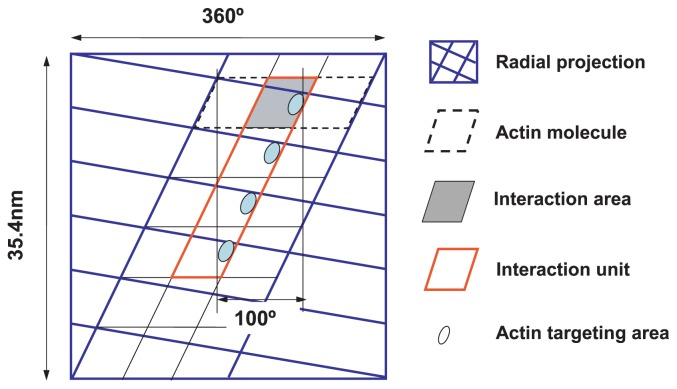
It is convenient to use radial projection of the actin filament12 to describe the movement of the myosin head on actin molecules, as shown in Figure 1. The interaction area on the actin molecule is shown by a shadowed rhomboid on the radial projection. Each of the interaction areas is assumed to contain the actin-targeting area and is also assumed to include part of the adjacent actin molecule. In addition, an interaction unit is defined as a region on the actin filament composed of four adjacent interaction areas along the right-handed long-pitch actin strand.
Figure 1.
Definition of interaction area and interaction unit. A radial projection of the actin filament of a half helical pitch is shown by solid blue lines. The area corresponding to an actin molecule is shown by dotted black lines, including the space between neighboring actin molecules. The interaction area on the surface of the actin molecule is represented by a shaded rhomboid. The interaction unit, consisting of four adjacent interaction areas, is framed by red lines. The actin target areas are tentatively represented by ellipsoids in the interaction area.
The width (d) of the interaction area is determined to satisfy the following three conditions: 1) four target areas on the interaction unit are located within 100° azimuths, 2) the sliding direction of a myosin head at half Vmax (1/2 Vmax) is parallel to the axis of the actin filament, and 3) the length of the trace of myosin movement on the interaction unit at 1/2 Vmax is equal to the sliding length of the myosin head along the actin filament. The calculated width d of the interaction area is 4.62 nm. This means that the interaction area occupies about 1/4 of the surface area of the actin molecule. In Figure 1, the lower side of the interaction area denotes the direction of the z-band of a sarcomere; muscle contraction occurs when the myosin head slides downward on the interaction area.
Twists in actin filaments: Analysis of molecular behavior in in vitro motility-assay systems
Twists in actin filaments sliding on a myosin-coated glass surface7 or on a myosin track8 have been reported. When the pointed end of an actin filament was stuck on the surface, Tanaka et al. observed a right-handed super-coil of the actin filament (Fig. 2A), buckling of the actin filament (Fig. 2B) or a left-handed super-coil of the actin filament (Fig. 2C), while Nishizaka et al. most frequently observed a left-handed super-coil of the actin filament on the myosin track (Fig. 2C). In the case of the myosin track, the pointed end of the actin filament was attached to the glass surface. These results suggest that the force acting at a cross-bridge contains a torque component around the axis of the actin filament and that the direction of the force acting on the myosin head varies depending on conditions.
Figure 2.
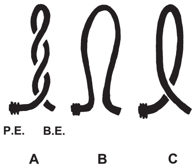
Twists and buckling of actin filaments observed in vitro. (A) Right-handed super-coiled actin filament. (B) Buckled actin filament. (C) Left-handed super-coiled actin filament. PE and BE represent the pointed and barbed ends of the actin filament, respectively. The pointed end of the actin filament is sticks by chance to a glass surface or is attached to the glass surface as illustrated.
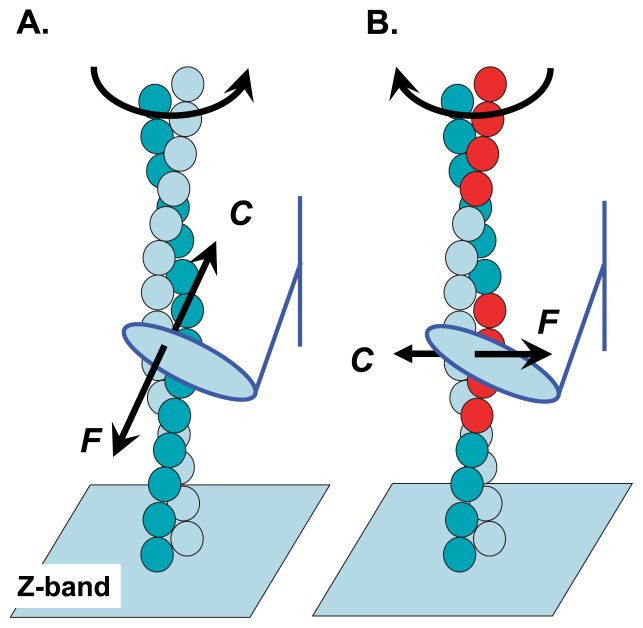
In this section we analyze the observations cited above and clarify the relationship between the direction of the force and the load acting at the cross-bridge. It is likely that myosin heads are randomly oriented on the myosin-coated glass surface, while myosin heads in the myosin track seem to be highly oriented. Thus, the number of myosin heads effectively binding to the actin filament to promote the sliding movement is larger on the myosin track than on the myosin-coated glass surface. As a result, the load shared by each myosin head during the sliding movement of the actin filament will be smaller on the myosin track than on the myosin-coated glass surface. It is supposed that the experiment on the myosin track that caused the left-handed super-coil of an actin filament (Fig. 2C) simulated the sliding movement of the myosin head on the actin filament under no-load or light-load conditions (Fig. 3A). In contrast, the force that caused the right-handed super-coil of an actin filament (Fig. 2A) on the myosin-coated glass surface corresponded to the force acting under heavy-load conditions (Fig. 3B). An actin filament (Fig. 2B) buckles when the myosin head slides parallel to the axis of the actin filament, because the torque component is not generated under this condition.
Figure 3.
Direction of force acting at a cross-bridge in muscle. (A) Direction of force F and counteraction C acting on an actin molecule under rapid-sliding conditions. This counteraction causes a right-handed super-coil of the actin filament in in vitro motility assay systems in which the pointed end of the actin filament is fixed to a glass surface. (B) Direction of force F and counteraction C acting under isometric conditions. This counteraction causes left-handed super-coil of the actin filament in in vitro motility assay systems. Note that the direction of the torque component changes with shortening conditions. Red balls represent the actin molecules included in a particular interaction unit.
In muscle, the barbed end of an actin filament is fixed at the z-band of the sarcomere. This situation is different from that of the tethered actin filament; therefore, in muscle, the same rotational movement of the myosin head around the axis of the actin filament twists a thin filament in the opposite direction to that observed in in vitro motility assay systems. Figure 3 illustrates the direction of force F acting on the myosin head and that of counteraction C acting on the actin molecule of thin filament in muscle. Several x-ray diffraction studies on shortening muscle fibers and/or those during isometric contraction have reported lattice-spacing changes13 or twists in actin filaments14,15. The reported directions of the twists in the actin filaments are consistent with those suggested above.
Based on these points, we conclude that the force generated at a cross-bridge contains torque components around the axis of the actin filament and that the direction of the force, i.e., the sliding direction of the myosin head on the actin molecule, varies with the imposed load. We defined force F, which is generated at a cross-bridge, and developed the following premise.
Premise 3
It is assumed that the AM* complex generates force F for muscle contraction. The direction and magnitude of force F varies with the external load P and the internal load ρ, which are imposed on myosin M* of the AM* complex. The sliding movement of the myosin head is assumed to be constrained motion on the interaction area subjected to the constraint force F. Loads P and ρ move on the interaction area with the myosin head.
Epexegesis on Premise 3
Enormous numbers of myosin heads are included in muscle. For example, a muscle fiber 60 μm across by 1cm length contains about 1012 myosin heads. We assume that load P shared by each myosin head is very small and the sliding movement of the myosin head is determined only by force F, while load P causes molecular distortions of the myosin head and/or the actin of the AM* complex to vary the direction of the generated force F.
In the AM* complex we suppose a potential valley, which determines the direction and magnitude of force F. The potential valley changes its profile due to molecular distortions of the myosin head and the actin molecule caused by loads P and ρ. As a result, the direction and magnitude of force F vary with the load.
Modeling of myosin movement in a single interaction area
In this section we describe the sliding movement of a myosin head in a single interaction area of the actin molecule. Premise 4 and 5 are introduced to explain the molecular behavior of the myosin head in the interaction area that is coupled to the twists in the actin filament.
Premise 4
The direction of force F, i.e., the sliding direction of myosin head M* in the interaction area is assumed to vary with load P. In other words, the angular component θ, which represents the effect of the load on the sliding direction of myosin head M*, is assumed to be proportional to load P and is given as:
| (1) |
as a result force F acting on the myosin head, is expressed as a function of θ, i.e., F(θ).
Epexegesis on Premise 4
Above, we introduced the interaction area on each actin molecule. Figure 4A shows the interaction area and its coordinates. The L- and H-axes are parallel and perpendicular to the axis of the actin filament, respectively. Angle α denotes the direction of the groove between the right-handed long-pitch strands of the actin filament on the radial projection; thus, α is constant. Force F(θ), the direction of which is the sliding direction of the myosin head, and load P+ρ are shown. The myosin head is assumed to start sliding in the interaction area at point O. In Equation (1) we assumed a linear relation between angle θ and the imposed load to simplify the model. The sliding direction of the myosin head in the interaction area is defined by angle α+β+θ, which is given counter-clockwise from the H-axis, where angle β denotes the effect of the internal load ρ on the sliding direction of the myosin head without the external load P, i.e., P=0, and is given as β=kρ. In the following discussion, the direction given by the angle α+β+θ is called direction θ owing to parameter θ. The direction θ of the myosin head sliding at maximum velocity Vmax is assumed to be given by α+β, because under this condition P=0 and θ=0. At half the maximum velocity 1/2Vmax, the sliding direction of the myosin head is assumed to be parallel to the axis of the actin filament; thus, direction θ is defined by α+β+θ=π/2. In the same way, direction θ under isometric contraction is defined by α+β+θ=π.
Figure 4.
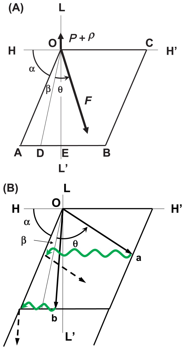
Illustrations of the sliding direction of a myosin head in the interaction area. (A) Definitions of parameters describing the sliding movement of a myosin head in the interaction area. The L-axis is parallel to the axis of the actin filament and the H-axis is perpendicular to the L-axis. The rhomboid OABC represents the interaction area. The myosin head is assumed to start its sliding movement at the original point O, and it slides in various directions depending on load P. Directions OD, OE and OC denote the sliding direction of the myosin head at Vmax (P=0), 1/2 Vmax and V=0 (P=P max), respectively. (B) Examples of sliding movements of a myosin head under heavy-load conditions (arrow Oa) and under light-load conditions below 1/2 Vmax (arrow Ob). Black arrow denotes the sliding trace of the myosin head in the interaction area. The green wavy arrow denotes Brownian movement of the myosin head around the long axis of the actin filament after dissociation of the myosin head from the actin molecule. The myosin head continues to slide in the interaction area under the given conditions, as shown by broken arrows.
Premise 5
Two types of sliding movements of the myosin head are possible in the interaction area. Under heavyload conditions, angle θ is large, and the myosin head that has slid in the interaction area in direction θ reaches the right-side edge of the interaction area, as shown by arrow Oa in Figure 4B. At this moment, if the myosin head is in the high-energy state M*, it dissociates from the actin molecule and is subject to Brownian movement around the actin filament; then, it associates with the left-side edge of the interaction area of the same actin molecule and continues to slide in direction θ. In such cases, the myosin head M* slides in the same interaction area several times depending on the load conditions.
In contrast, under light-load conditions, angle θ is small, and the myosin head that has slid in the interaction area reaches the lower edge of the interaction area, as shown by arrow Ob in Figure 4B. At this moment, if the myosin head is still in the high-energy state M*, it dissociates from the actin molecule on which it has just slid and is subject to Brownian movement around the actin filament; then, it associates with the next actin molecule and continues to slide in the interaction area of this new partner actin molecule.
Epexegesis on Premise 5
It is informative to refer to the molecular behavior of a myosin head in the resting state of muscle contraction in order to consider the process in which a myosin head that has just slid in the interaction area changes its partner actin molecule. In the resting state, a myosin head energized by ATP hydrolysis fluctuates around an actin filament16,17 and does not form an AM* complex. The time constant of Brownian movement of the myosin head around the actin filament is about 0.2–2 μs, much shorter than the time constant of sliding movement of the myosin head on the actin filament. It is likely that the myosin head that has dissociated from the actin molecule after sliding in the interaction area will find its next partner actin molecule during Brownian movement around the actin filament. The direction of the movement of the myosin head caused by Brownian movement is assumed to be perpendicular to the axis of the actin filament (Fig. 4B); thus, it makes no contribution to the shortening distance of the myosin head along the axis of the actin filament.
In this model, traverse sliding of the myosin head in the interaction area is assumed (Fig. 4A, B). As a result, the direction of the torque component around the axis of the actin filament changes depending on the sliding velocity.
Modeling of myosin movement in several interaction areas
As a result of the sliding movement of a myosin head in several interaction areas under the given load P, a set of sliding traces of the myosin head is obtained in interaction areas. An example is shown in Figure 5. Black arrows represent the movement of the myosin head in each interaction area, and green arrows represent Brownian movement of the myosin head during the exchange process of a partner actin molecule. For simple presentation, we use the interaction unit, which is defined as four adjacent interaction areas. A trace of movement of the myosin head on the interaction unit driven by force F(θ) is represented by a long broken line given by the summation of vector components representing the sliding movements (Fig. 5). In order to derive shortening length Ls, we suppose the trace of the myosin head that is assumed to start at the original point O and finishes at point X. We define point S, which gives the intersection point of segment OX or that of an extension of segment OX with the right-side edge of the interaction unit. Then, the length of segment OS gives the sliding distance Lu of the myosin head on the interaction unit and the projection length of segment OS onto the L-axis gives the shortening length Ls of the myosin head along the axis of the actin filament during sliding movement on the inter-action unit (Fig. 5). The shortening length Ls is given as follows:
Figure 5.
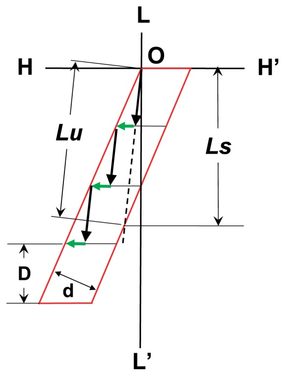
Sliding traces of a myosin head in interaction areas and expressions of sliding length on the interaction unit. Black arrows represent the sliding movement of the myosin head in each interaction area, and green arrows denote Brownian movement to change the interaction area. The broken line which starts from point O shows the sliding trace of the myosin head on the interaction unit defined by the summation of each vector component representing the sliding movement of the myosin head in each interaction area. Definitions of the shortening distance Ls and the sliding distance on interaction unit Lu are shown (See text).
| (2) |
where d denotes the width of the interaction unit.
We introduce the duration of time t(P), which is required for the sliding movement of the myosin head to cut across the interaction unit with load P. Then, shortening velocity V(θ) of the myosin head along the axis of the actin filament is defined by Ls (θ)/t(P) and is given as follows:
| (3) |
As defined above, angle θ is proportional to load P, and Equation 3 represents the relationship between the load and sliding velocity of the myosin head.
Load-velocity relationship: Comparison of theoretical expectation with experimental data
Equation 3 is not practical because it contains t(P) explicitly, and we have no information about the profile of t(P) as a function of load P. For simplification, we have developed the following premise:
Premise 6
The duration of time t(P) that is required for the myosin head to cut across width d of the interaction unit is assumed to be independent of load P and the constant, i.e., t(P)=τ.
Then, Equation 3 takes a simple form:
| (4) |
or as a function of load P
| (5) |
The normalized load-velocity relationship V(θ)/Vmax is given by
| (6) |
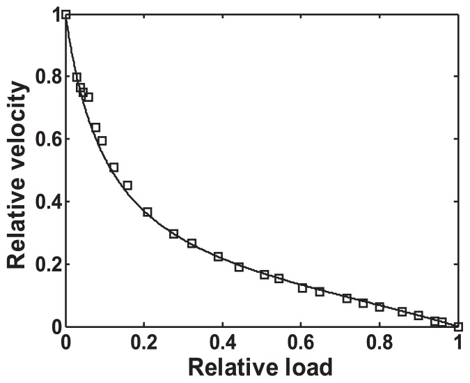
As shown in Figure 6, the theoretically derived, normalized load-velocity relationship V(θ)/Vmax is consistent with the experimental data from single muscle fibers18 (Fig. 2 of Edman & Hwang, 1977). This result indicates that Premise 6 is appropriate, even under heavy-load conditions, including the isometric condition, where θ becomes larger and the myosin head slides in the interaction area of a single actin molecule throughout the duration of time t(P) (as shown in Fig. 4A). While under these conditions, the ATPase rate of the myosin head becomes slower than that of the maximum rate.
Figure 6.
Load-velocity relationship: Comparison of the theoretical indication and experimental data. Normalized load P/Pmax = θ/θmax vs. normalized velocity V/Vmax is plotted. It is assumed that (1) angle α+β+θ = π/2 at 1/2 Vmax; the myosin head slides along L-axis at V= 1/2 Vmax, and (2) α+β+θmax =π at isometric contraction, and (3) the numerical value of α is obtained by the inclination angle of the right-handed long-pitch strand on the radial projection; that of β is determined by the sliding direction at Vmax on the interaction unit of the radial projection. The results are in good agreement between the theoretical indication (solid line) and the experimental data (square) reported by Edman and Hwang (Fig. 2 of Edman & Hwang, 1977). Here, α and β are (67/180) π and (11/180) π radian, respectively.
It should be noted that the velocity range V(θ)<0.25 Vmax corresponds to the load range of 0.3 Pmax to Pmax. The AM* complex supports the sliding movement of a myosin head in a wide range of P on a single actin molecule.
As shown in Figure 7, velocity vector Vu(θ) of the myosin head on the interaction unit is decomposed into two orthogonal vectors, Vp(θ) and Vn(θ), which are parallel and perpendicular to the direction of the groove between the right-handed long-pitch strands of the actin filament, respectively. It should be noted that the velocity component Vp(θ) vanishes when Vu(θ) becomes equal to Vn(θ) with an increase of load P, while the velocity component Vn(θ) is constant and independent of the load. This model indicates that the myosin head has two components of sliding velocity, Vp(θ) and Vn(θ), on the surface of the actin molecule, and that component Vp(θ) varies its magnitude and direction with the increase of the load while component Vn(θ) is independent of the load.
Figure 7.
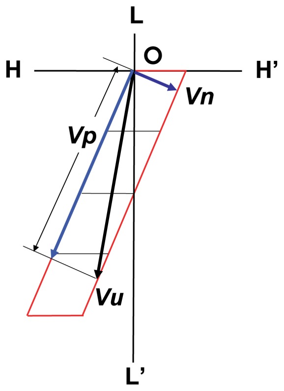
Two components of sliding velocity Vu(θ) on the interaction unit. Vp(θ) decreases with the increase of the load, while Vn(θ) is independent of the load change. Vp(θ) vanishes around the shortening velocity V(θ)=0.076 Vmax when the sliding direction of the myosin head becomes perpendicular to the direction of the groove of actin strands, i.e., the direction of Vn(θ). Note that Vp(θ) takes the opposite direction with further load increase.
ATPase rate of a myosin head during sliding movement: Analysis of experimental data
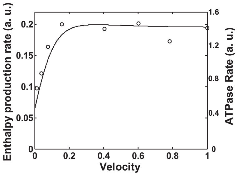
Harada et al. measured the sliding velocities of actin filaments on a myosin-coated glass surface and the ATPase rate of myosin heads coating the glass surface during the sliding of actin filaments by varying the ATP concentration in the medium4,5. From their results (Fig. 4 of Harada et al., 1987), the relationship between the ATPase rate of the myosin head and the sliding velocity of the actin filament can be derived, as shown by the circles in Figure 8. The ATPase rate exhibits a saturation-like profile with the increase of sliding velocity of the actin filament. This result indicates the molecular nature of actomyosin ATPase; i.e., the ATPase rate of a myosin head is virtually independent of sliding velocity above 0.3 Vmax, and it decreases with the decrease in sliding velocity below 0.3 Vmax. In shortening muscle, the maximum rate of enthalpy production is observed in the region of 0.4 Vmax, and the rate observed at Vmax is only slightly decreased19. The ATPase rate derived above shows a similar tendency.
Figure 8.
Actin-activated myosin ATPase rate and the enthalpy production rate of myosin head calculated by the revised Hill’s formulae. Both are plotted against the normalized sliding velocity. The circles show the actin-activated myosin ATPase rate derived by analyzing Harada et al.’s experimental data in the case of double-headed myosin (Fig. 4 of Harada et al. 1987) using ATPase concentration as a parameter. The solid line represents the enthalpy production rate of the myosin head calculated by the revised Hill’s formulae based on the normalized load-velocity relationship shown in Figure 6.
In muscle, the relationships between the rate of enthalpy production ( + ) and the shortening velocity are known as Hill’s formulae20. The rate of work production and that of heat production are defined by:
| (7) |
| (8) |
where m denotes the maintenance heat rate and is given by m= 0.74 P′V′. P′ is 1/2 P0, and V′ is the shortening velocity under load P′. The rate of enthalpy production given by Hill’s formulae is calculated based on the normalized load-velocity relationship shown in Figure 6; however, the enthalpy production rate given by Equations 7 and 8 is slightly increased at Vmax. In order to simulate the general form of the enthalpy production rate reported for shortening muscle, coefficient 0.133 was used instead of 0.16 in Equation 8. The solid line in Figure 8 represents the enthalpy production rate given by the revised Hill’s formulae, which is calculated on the basis of the theoretically derived load-velocity relationship for a single myosin head. The calculated enthalpy production rate and the myosin ATPase rate observed in the in vitro motility assay system showed a similar dependency on relative sliding velocities. Thus, we can represent the functional form of the ATPase rate ATPR(θ) of a single myosin head by that of the enthalpy production rate given by the revised Hill’s formulae. Originally, Hill’s formulae represented the enthalpy production rate of shortening muscle. The result shown in Figure 8 indicates that the energy property of shortening muscle is explained by that of a single myosin head. It is likely that the active fraction of myosin heads during muscle contraction is constant, because if the number of the active fraction of myosin heads during muscle contraction varies with sliding velocity, the functional form of the enthalpy production rate of shortening muscle should be different from that of the single myosin head.
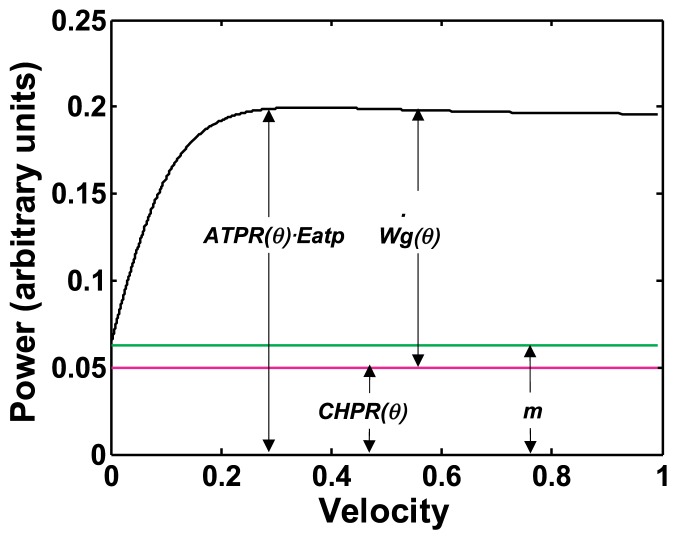
The enthalpy production rate of shortening muscle corresponds to the power, i.e., time rate of energy released by the shortening muscle; thus, product ATPR(θ) · Eatp denotes the power of a single myosin ATPase, where Eatp is the energy supplied by ATP hydrolysis. Strictly speaking, the abscissa axis of Figure 8 is the relative sliding velocity and is not angle θ. In this model, however, one-to-one correspondence is assumed between the sliding velocity and angle θ. Then, the functional form of ATPR(θ) is expressed by angle θ instead of the sliding velocity.
Gross work performed by a myosin head and power of molecular machinery
Here we define the gross work Wg(θ) performed by the myosin head during the sliding movement on the interaction unit as follows:
| (9) |
where Lu(θ) denotes the sliding distance of the myosin head on the interaction unit shown in Figure 5.
The work necessary to slide load P in the direction of force F in the interaction area is given by a product of the load component P·sin(α+β+θ) and the sliding distance in the interaction area Lu(θ) as P·sin(α+β+θ)·Lu(θ) (See Fig. 5). This is equal to work W(θ) to move load P in the distance of Lu(θ)·sin(α+β+θ), i.e., P·Lu(θ)· sin(α+β+θ), along the L-axis, i.e., W(θ)=P·Lu(θ)·sin(α+β+θ). Work that is done by force F, except work for load P, which corresponds to the work unable to be performed using the AM* complex and dissipates as heat H(θ), is given by H(θ)= (F(θ)−P·sin(α+β+θ))·Lu(θ)=F(θ) ·Lu(θ)−P·sin(α+β+θ)·Lu(θ). As a result, the gross work is given by Wg(θ)= W(θ)+H(θ); therefore, it is reasonable to use the gross work in the discussion of energy characteristics of the cross-bridge cycle.
Suppose a time derivative of the gross work (θ); this represents the power of the myosin head. In addition, we define the power of the constant heat production rate CHPR(θ), which resembles the maintenance heat rate of Hill’s formulae (m), as a function of the sliding direction θ. On the basis of the energy conservation law, the enthalpy production rate of the myosin head during sliding movement on the interaction unit is given by the product of Eatp and the difference between the ATPase rate ATPR(θ) of the myosin head and the constant heat production rate. We can then make the following premise that defines the energy balance at the cross-bridge as follows:
Premise 7
The power of the gross work released by the myosin head is given by:
| (10) |
Epexegesis on Premise 7
This premise indicates that the energy balance observed in shortening muscle is also realized in a single myosin head during the sliding movement in the interaction area. Relationships among the power of the gross work (θ), the power of energy supplied by ATP hydrolysis ATPR(θ)·Eatp, and that of CHPR(θ) are explained in Figure 9. The constant heat-production rate CHPR(θ), which resembles the maintenance heat rate in Hill’s formulae, is assumed to be independent of the sliding velocity of the myosin head, and it is not transformed into gross work. The value of CHPR(θ) is tentatively assumed to be 0.05. This value is less than 0.0629 of the maintenance heat rate (m) in Hill’s formulae that is calculated assuming the normalized load-velocity relationship shown in Figure 6, because the gross work Wg(θ) has a positive value under isometric contraction. The myosin head is still sliding on the interaction unit along the H-axis under the isometric condition with sliding velocity Vu(θmax), while the shortening velocity V(θ) along the L-axis is equal to zero.
Figure 9.
Relationship among the power of energy supplied by single ATP hydrolysis ATPR(θ)·Eatp, the power of the constant heat component CHPR(θ), and the power of the gross work (θ) of a myosin head. The functional form of the power of energy supplied by ATP hydrolysis is assumed to be the same as the enthalpy production rate (shown in Fig. 8) given by the revised Hill’s formulae. The maintenance heat rate m, which is the power of maintenance heat given by Hill’ formulae is also shown.
Derivation of a functional form of force F
We can derive the expression of the functional form of force F(θ) from Equation 9. Force F(θ) is given as:
| (11) |
| (12) |
| (13) |
| (14) |
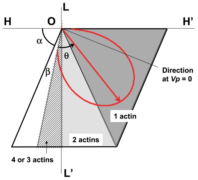
Force F(θ) given by Equation 13 is depicted in the interaction area by polar representation as functions of magnitude and sliding direction θ of force F(θ) (Fig. 10). The number of actin molecules on which a myosin head slides during τ is appended to the corresponding zone of the interaction area. The result indicates that a single actin molecule covers a wide range of sliding directions, especially under heavy load conditions. The sliding direction at Vp=0 is also shown.
Figure 10.
Polar display of relative magnitude and direction of force F(θ) in the interaction area. A red arrow from the original point O represents force F(θ) in direction θ, and the red curve corresponds to the trace of the pointed end of force F(θ) with the change of load P. The direction of F(θ) at P=0 and P=Pmax is given by the directional angle of α+β (left end-point of the curve) and that of α+β+θmax =π (right end-point of the curve) from the H axis, respectively. Numerical values of F(θ) are calculated by Equation 13, in which the functional form of the ATPase rate is represented by the revised Hill’s formulae. The value of the constant heat production rate CHPR(θ) is assumed to be 0.05. It should be noted that the value of F(θ) is relative, and it depends on the expressive form of the ATPase rate. The sliding direction at Vp=0 is also shown.
Role of energy supplied by ATP hydrolysis
As shown in Figure 9, the power of gross work, i.e., ATPR(θ) · Eatp – CHPR(θ), is virtually constant and is roughly independent of the sliding velocity of the myosin head under a wide range of sliding velocities. This indicates that the amount of energy released by the myosin head onto an actin molecule during sliding movement varies with the sliding velocity, because the time that the myosin head stays on the actin molecule varies with the sliding velocity. If the myosin head continuously discharges the energy supplied by ATP hydrolysis over time, the energy level of the myosin head at the moment of association with an actin molecule is distinct from each actin molecule. In such cases, it is difficult to presume the same molecular state of the AM* complex at the change of a partner actin molecule that is assumed inexplicitly. This insight suggests that the energy supplied by ATP hydrolysis is used not for individual interactions between the myosin head and the actin molecule, but instead for a common mechanism necessary for the sliding movement. The following mechanism is assumed to explain molecular events during the cross-bridge cycle.
Premise 8
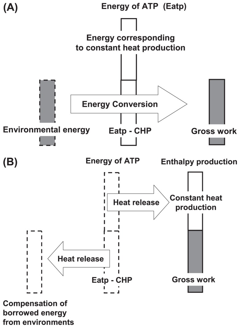
The constant heat production (CHP), which corresponds to part of the energy supplied by ATP hydrolysis, is used to maintain the myosin head in the high-energy state M*. The rest of the supplied energy is equivalent to the amount of energy which the actomyosin system can borrow from the environment, and AM* complex converts the borrowed energy into gross work production, i.e., work and heat production. When the lifespan of the myosin ATPase ends, the myosin head releases the energy supplied by ATP hydrolysis into the environment as heat. An energy balance among constant heat production, gross work, and the energy supplied by ATP hydrolysis is then achieved, as shown in Figure 11A and 11B.
Figure 11.
Schematic presentation of energy flow at the AM* complex. (A) Energy flow during sliding movement. The molecular mechanism borrows energy from the environment and converts it into gross work. (B) Energy flow after the end of the ATPase lifetime. The energy supplied by ATP hydrolysis is released into the environment as heat. The borrowed energy is covered by part of the released energy. The energy used to maintain the high-energy state of the myosin head is released as heat into the environment.
Modeling of energy-borrowing mechanism in AM* complex during sliding movement
In this section we discuss the possible mechanism of the cross-bridge cycle that realizes Premise 8. Suzuki et al. reported that a myosin head energized by ATP hydrolysis is in a dehydrated state21. In addition, the binding of actin to myosin induces an equilibrium shift in the macrostate of myosin toward a dehydrated state22. These results suggest that the AM* complex provides hydrophobic conditions for actomyosin interaction and that the molecular state of the myosin head M* differs before and after the sliding movement. We can distinguish the state of myosin head M* between M*before and M*after. M*before is the state before association with the actin molecule and M*after is the state after sliding on the actin molecule and dissociation from the actin molecule, respectively. M*after is assumed to be more dehydrated than M*before. It is likely that M*after released from the actin molecule is hydrated during Brownian movement around the actin filament and becomes M*before again. The myosin head then associates with a new actin molecule. These descriptions are summarized in two premises.
Premise 9
It is assumed that the state of myosin M* is distinguished between M*before and M*after; the state before association with the actin molecule is denoted as M*before, and the state just after dissociation from the actin molecule is denoted as M*after. M*before is dehydrated in the force generation process and M*after, a product of the dehydration process, is released. During Brownian movement around the actin filament, the myosin head in the state of M*after recovers its state of M*before by hydration of M*after through interactions with the surrounding water molecules, and then the re-formed myosin head M*before associates with a new partner actin molecule to continue the sliding movement.
Premise 10
An energy-borrowing mechanism is assumed which converts the potential difference between M*before and M*after into enthalpy production. In other words, the energy used for force generation coupled with the sliding movement is assumed to be supplied by the hydration of M*after through the reformation process of M*before. The energy used for force generation has an external origin.
Modeling of energy-accumulating mechanism in AM* complex during sliding movement
In this section we analyze the energy flow included in a cross-bridge cycle. The reaction steps included in the cross-bridge cycle are classified into two groups, as shown in Figure 12. One reaction group passes inside the AM* complex and includes the following steps: (a) AM* complex formation, i.e., A+M*↔AM*, (b) generation of M*after coupled with sliding movement of the myosin head on the actin molecule, i.e., AM*before→AM*after, and (c) dissociation of AM*after, i.e. AM*after→A+M*after. The other reaction group passes outside the AM* complex and includes the following steps: (d) hydration of M*after for reformation of M*before, i.e. M*after→M*before in the surrounding medium.
Figure 12.
Molecular events and energetic processes included in the cross-bridge cycle. Arrows (a), (b), (c) and (d) denote energetic processes.
It is likely that step (c) is an energy-requiring step necessary for the dissociation of AM*. We consider that step (b) includes several types of energetic processes: (1) generation process of M*after from M*before, (2) external work production process against the external load P, (3) internal work production process against the internal load ρ, and (4) energy accumulation process for dissociation of AM*. Except for the energy used in process (2) for external work production, the energy used in processes (1), (3), and (4) finally becomes heat production, which corresponds to part of the heat production released from shortening muscle. It should be noted that the constant heat production in the model is not included in the heat production from gross work. The constant heat production is released as heat after the end of the lifespan of myosin ATPase. Thus, we can state the following premise.
Premise 11
The sliding movement of the myosin head in the interaction area, i.e., the gross work-generating process on the actin molecule, has two energetic aspects. One is the work-generating process against the external and internal load, and the other is the energy-accumulating process in the AM* complex to refresh the molecular state of the myosin head itself to continue the sliding movement, i.e., generation and release of M*after.
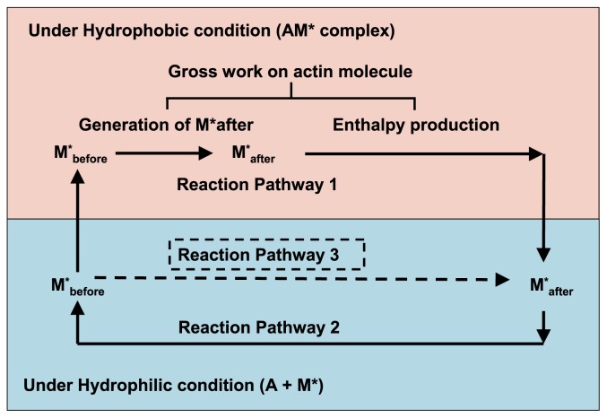
The energy processes included in the cross-bridge cycle are summarized in Figure 13. These are categorized into two reaction pathways; reaction pathway 1 and reaction pathway 2. Reaction pathway 1 starts at M*before under hydrophilic conditions and it continues under hydrophobic conditions in the AM* complex, including dissociation of the AM* complex, as shown in Figure 12, and reaches M*after under hydrophilic conditions; therefore, reaction pathway 1 includes two energy events, i.e., generation of M*after and generation of enthalpy production. Both of these energy events are generated by the gross work performed on the actin molecule. It should be noted that the gross work is defined from the interaction unit by Equation 9; therefore, the ‘gross work on actin molecule’ shown in Figure 13 should be regarded as a product of the force and the sliding distance of the myosin head on the action molecule. Reaction pathway 2 starts at M*after in hydrophilic conditions and it reaches M*before under hydrophilic conditions. It corresponds to hydration step (d) of M*after for the reformation of M*before, as shown in Figure 12.
Figure 13.
Schematic presentations of reaction pathways and energetic events included in the cross-bridge cycle. The cross-bridge cycle includes two reaction pathways. Reaction pathway 1 occurs under hydrophobic conditions and reaction pathway 2 occurs under hydrophilic conditions. ‘Gross work on actin molecule’ includes the energy necessary for the generation of M*after and enthalpy production. Pathways 1 and 3 show a schematic illustration of energy balance in the cross-bridge cycle. Pathway 1 includes the generation process of M*after from M*before and the process of enthalpy production. The potential of the reaction product of two pathways at the goal is the same; therefore, the potential difference generated by pathway 2 covers gross work production on the actin molecule in addition to the energy required for the generation of M*after (see text for details).
Energy balance during a cross-bridge cycle
As mentioned above, the AM* complex induces hydrophobic conditions; thus, the energy required to generate M*after from M*before in AM* will be smaller than that required under hydrophilic conditions, i.e., in solution outside of AM*. Suppose the following two reaction pathways, reaction pathway 1 and reaction pathway 3, shown in Figure 13. Pathway 1 is defined by the following reactions: M*before in hydrophilic conditions→M*before in hydrophobic conditions (AM*before)→M*after in hydrophobic conditions (AM*after)→ M*after in hydrophilic conditions. Reaction pathway 3 is defined by the reverse reaction of reaction pathway 2, i.e., M*before in hydrophilic conditions→M*after in hydrophilic conditions. As a potential difference between M*before and M*after, under hydrophilic conditions, both should be independent of the reaction pathways and the amount of energy required in these two reaction pathways should be equal. These propositions indicate that pathway 1 affords enough energy to cover the necessary energy for the generation of M*after and for enthalpy production.
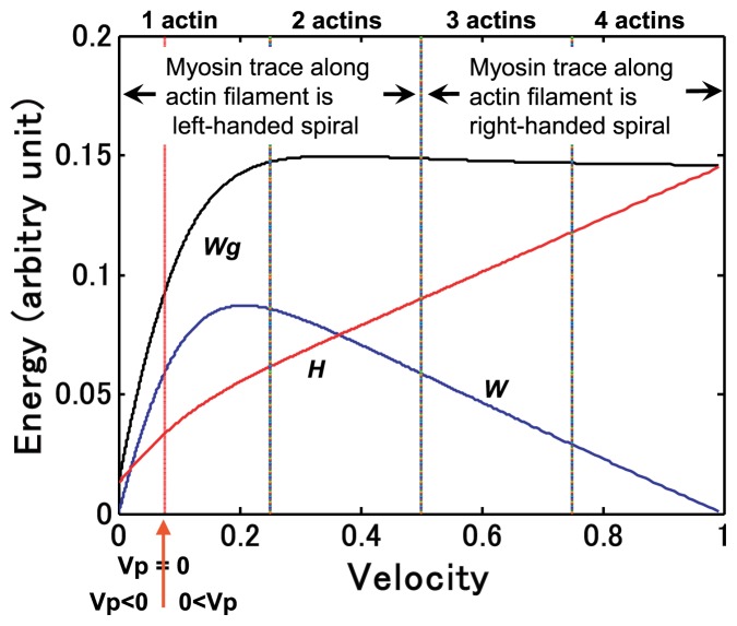
Relationships among sliding velocities, energetic quantities and the molecular behaviors of a myosin head are summarized in Figure 14. The number of actin molecules on which the myosin head slides during duration τ and characteristic movements of the myosin head around the actin filament are indicated.
Figure 14.
Relationships among gross work production, sliding velocities, and molecular behavior of myosin head on actin molecules. Note that constant heat production is omitted. The black solid line represents gross work Wg(θ). The blue line denotes work production W(θ). The red line shows heat production H(θ), defined by Wg(θ)−W(θ). The relationship between the number of actin molecules on which a myosin head slides during τ and the sliding velocity is shown at the top. Velocity 0.076 Vmax at which Vp(θ)=0 is shown by the red arrow.
Discussion
Width of the interaction unit
For modeling, an interaction unit with four interaction areas is assumed. The sliding direction of the myosin head at 1/2 Vmax is assumed to be parallel to the axis of the actin filament. This condition indicates that the angle that gives the sliding direction satisfies α+β+θ=π/2. The calculated width of the interaction unit d is 4.62 nm, which is given by d=2D sin(β+θ)=2D cos α, where D denotes the diameter of the actin molecule along the actin filament, and D=5.9 nm is assumed. Kitamura et al. reported that myosin slides on six actin molecules with the hydrolysis of a single ATP molecule in an in vitro system9. It is likely that if the internal load of an in vitro system is less than that of an in vivo system, angle β, which gives the sliding direction under a no-load condition, will become smaller. In such a case, if stereoscopic hindrance were avoided, it would be possible for the myosin head to slide on six actin molecules.
Internal load and its effect on myosin movement
In this model, internal load ρ is defined as representing internal factors which affect the sliding movement of the myosin head on the actin molecule. The contribution of the internal load to the sliding direction of the myosin head in the interaction area is given as β=kρ and the same coefficient k is assumed in the case of θ=kP. Strictly speaking, coefficient k appearing in β and θ would not be the same; however, a practical factor which affects the movement of the myosin head in the model is angle β, and as we discussed above, it is assumed to be constant. The shape of the load-velocity relationship changes with the value of β; therefore, β seems to represent the characteristics of a particular actomyosin system.
Two components of sliding velocity: Vp and Vn
The sliding velocity Vu(θ) of the myosin head defined on the interaction unit is decomposed into two orthogonal vectors, Vp(θ) and Vn(θ). Here, Vp(θ) and Vn(θ) are parallel and perpendicular to the direction of the groove between the right-handed long-pitch actin strands, given by angle α on the radial projection. To derive the load-velocity relationship, the duration of time t(P), during which the myosin head cuts across the interaction unit, is assumed to be constant (Premise 6); i.e., Vn(θ) is constant and independent of load P. In contrast, Vp(θ) decreases with the increase of load P. The shortening velocity V(θ) at which Vp(θ) becomes zero is given by condition β+θ=π/2. Then, Vp(θ) changes direction below V(θ)<0.0762 Vmax (Fig. 7). The sliding movement with negative Vp(θ) corresponds to very slow contractions, including isometric contractions. These results suggest that the myosin head M* has two different modes of sliding movement; one for sliding on multiple actin molecules and another one for sliding on a single actin molecule with a heavy load. It is likely that the decrease in the myosin ATPase rate under slow sliding conditions is affected by a modal change of the internal state of the myosin head and/or that of the actin molecule in the AM* complex because it is reasonable to assume that the internal state of the myosin head changes at the border of Vp(θ)=0. In this model, the number of actin molecules on which the myosin head slides during t(P) varies with the sliding velocity.
Key function of ATP
In this model, it is assumed that the energy supplied by ATP hydrolysis is used to retain a myosin head in the high-energy state M*, in which the myosin head is able to interact with actin molecules and to generate gross work Wg(θ) during the lifetime of myosin ATPase. As discussed above, the energy used for the sliding movement of the myosin head on the actin molecule is of external origin and is supplied by the environment through the hydration of M*after (Fig. 11). When the lifespan of myosin ATPase ends, the myosin head releases the energy given by ATP hydrolysis into the surroundings, which is why enthalpy production during muscle contraction basically coincides with the energy supplied by ATP hydrolysis of myosin ATPase. It is likely that the ATP molecule plays a double role, as a regulatory factor of the high-energy state of myosin head and an energy compensator of the energy borrowed from the environment for muscle contraction. In the tight coupling model of a molecular motor, the indirect connection between the energy supplied by ATP hydrolysis and the thermal energy used to perform work by the molecular motor is discussed by Thomas et al.23.
Another origin of external energy
It is assumed above that the hydration of M*after provides the energy necessary to generate the gross work. This idea gives greater importance to the chemical process, i.e., hydration of M*after. An alternative idea that stresses the validity of the physical process is also possible. If the internal and external loads decrease the entropy of the AM* complex due to structural change of the AM* complex, thermal fluctuation of the AM* complex possibly increases to compensate for the decrease of entropy of the system owing to entropic elasticity. In muscle contraction, large changes in entropy and enthalpy are known as entropyenthalpy compensation22. It is likely that the increased fluctuation in the AM* complex mediates gross work generation coupled with the sliding movement of the myosin head in the interaction area. In this case, the energy borrowed from the surroundings is thermal energy and the AM* complex converts it into gross work. When the lifetime of the myosin ATPase is over, the myosin head releases the energy supplied by ATP hydrolysis into the surroundings. Energy balance is therefore achieved as discussed above.
Enzyme fluctuation is important for functional development 24,25. It is noteworthy that AM* complex fluctuation is essential for the force-generation mechanism; however, it is outside the scope of this article to discuss the fluctuation of the molecular system, because it requires precise information on the structural and energetic properties of the AM* complex at the sub-molecular level.
Role of a double-headed myosin
The myosin head is assumed to be able to slide on four adjacent interaction areas of actin molecules under no-load conditions during t(P). The myosin head that had slid in the fourth interaction area reaches the lower edge of the interaction area of the fourth actin molecule. It then becomes difficult for the myosin head to find a new partner actin molecule to associate with because of the stereoscopic configuration of thin and thick filaments in muscle. A new candidate actin molecule that can associate with the myosin head without stereoscopic hindrance is an actin molecule included in another interaction unit located on another actin strand in the same spatial phase in the direction of the shortening movement (see Fig. 3B). Thus, the myosin head has to skip several actin molecules along the actin filament to reach a new partner actin molecule. In the sliding movement, if one of the heads of a double-headed myosin is able to interact with a new partner actin molecule while the other head is still in the interaction area of the fourth actin molecule, the sliding movement of the double-headed myosin along the actin filament will be smooth. This mechanism of smoothly changing the interaction unit on the actin filament is necessary for stable muscle contraction, especially for rapid shortening. The lifetime of myosin ATPase in frog skeletal muscle is about 3−1 sec at low temperature22, and this lifetime is too long for the myosin head to slide on a single interaction unit. It is likely that the myosin head slides on several interaction units with single cleavage of an ATP molecule during the lifetime of myosin ATPase.
Comparison of the proposed model with another loose coupling model of muscle contraction
Yanagida and his colleagues9 proposed the biased Brownian movement model of muscle contraction on the basis of a loose coupling mechanism between the sliding movement of the myosin head on actin molecules and ATP cleavage. We proposed an energy borrowing model of molecular behavior during muscle contraction in this article, also assuming a loose coupling mechanism. We draw comparisons between the biased Brownian movement model and the energy borrowing model.
In the biased Brownian model, the myosin head is driven by thermal fluctuation in the potential field around the actin filament. This results in the sliding movement of the myosin head on several actin molecules along the left-handed actin strand of the actin filament.
In contrast, in the energy borrowing mode, the molecular mechanism of the force generation is the interaction between the myosin head and the actin molecule. Traverse sliding of the myosin head in the interaction area depending on the load condition causes shortening, and results in directional change of the torque that causes two types of twists in actin filament during muscle contraction. The details of the interaction, however, remain to be elucidated.
The AM* complex is a mechanochmical system to generate mechanical displacement of the myosin head on the actin molecule and to convert chemical energy supplied by ATP hydrolysis into work and heat. Thus, the model of the molecular mechanism of muscle contraction should explain the coupling mechanism between the sliding movement and the energy conversion included in the cross-bridge cycle. In the biased Brownian movement model, it is assumed that multiple myosin heads move along the potential field given by the steric compatibility of the helical pitches of the actin filament. The role of energy supplied by ATP hydrolysis in the cross-bridge cycle is, however, not explicitly mentioned in the model.
In the energy borrowing model, the relationship among the energy supplied by ATP cleavage, gross work production (work + heat), and the energy source that is converted into gross work production in the AM* complex is clarified. The model provides the energy basis of the cross-bridge cycle from the aspect of a loose coupling scheme.
Concluding remarks
We have proposed a model of molecular behavior at a cross-bridge during force generation. The main premises for modeling are as follows: 1) the force generated at the cross-bridge includes a torque component around the axis of the actin filament and the direction of the force varies with load; 2) the key function of ATP is not as an energy source for sliding movement and enthalpy production, but to maintain the high-energy state of the myosin head, in which the myosin head is able to associate with the actin molecule to generate force; and 3) the energy used for enthalpy production is of external origin and is not the energy supplied by ATP hydrolysis.
The model successfully explains the experimental results at different levels of muscular samples; the twists in actin filaments observed in shortening muscle, the physiological properties of shortening muscle fibers, and energy balance between the energy supplied by ATP hydrolysis and enthalpy production during muscle contraction. The model indicates that the physiological properties of shortening muscle are determined directly by the property of a single molecular mechanism.
The energy aspects of the cross-bridge cycle are characterized by our model. The model strongly suggests the importance of the external energy borrowed from the environment, including thermal fluctuation of the AM* complex. To further understand the molecular mechanism of muscle contraction, a time-dependent study of the actomyosin complex, including regulatory proteins, is required.
Acknowledgements
The author thanks Professors S. Ishiwata, T. Kodama and F. Oosawa for their valuable discussions and encouragement.
Appendix
Glossary defining the terms in the text
- A
actin molecule
- AM*
actomyosin complex
- ATP
adenosine tri-phosphate
- ATPR(θ)
ATPase rate of myosin head
- C(θ)
counterforce acting on actin filament
- CHPR(θ)
constant heat-production rate of myosin head
- d
width of interaction area
- Eatp
energy supplied by ATP hydrolysis
- F(θ)
force acting on myosin head
- H
horizontal axis of interaction area
- H(θ)
heat production from myosin head
- k
proportional constant between parameter θ and load P
- L
long axis of actin filament, vertical axis of interaction area
- Ls(θ)
shortening distance of myosin head along L-axis of actin filament
- Lu(θ)
sliding distance of myosin head on interaction unit during t(P)
- m
maintenance heat rate in Hill’s formulae
- M
myosin head
- M*
myosin head in high-energy state energized by hydrolysis of ATP
- M*after
myosin head in high-energy state after sliding on actin molecule
- M*before
myosin head in high-energy state before sliding on actin molecule
- P
external load
- Pmax
maximum load at which V(θ)=0
- t(P)
time required for myosin head to cut across interaction unit
- V(θ)
shortening velocity of myosin head along L-axis of actin filament
- Vmax
maximum shortening velocity
- Vn(θ)
sliding velocity of myosin head perpendicular to direction of groove between right-handed long-pitch strands of actin filament
- Vp(θ)
sliding velocity of myosin head parallel to direction of groove between right-handed long-pitch strands of actin filament
- Vu(θ)
sliding velocity of myosin head on interaction unit in direction of θ
- W(θ)
work along the L-axis defined by P·Ls(θ)
- Wg(θ)
gross work defined by F(θ)·Lu(θ), which represents enthalpy production of myosin head during t(P)
- α
direction of the groove between the right-handed long-pitch strands of actin filament
- β
sliding direction of myosin head at P=0
- θ
sliding direction of myosin head on interaction area, the value of which is proportional to load P
- ρ
internal load
- τ
constant value which corresponds to the time required for myosin head to cut across interaction unit
References
- 1.Huxley AF. Muscle structure and theories of contraction. Prog in Biophys Biophys Chem. 1957;7:255–318. [PubMed] [Google Scholar]
- 2.Huxley HE. The mechanism of muscle contraction. Science. 1969;164:1356–1366. [PubMed] [Google Scholar]
- 3.Huxley AF, Simmons RM. Proposed mechanism of force generation in striated muscle. Nature. 1971;233:533–538. doi: 10.1038/233533a0. [DOI] [PubMed] [Google Scholar]
- 4.Harada Y, Noguchi A, Kishino A, Yanagida T. Sliding movement of single actin filaments on one-headed myosin filament. Nature. 1987;326:805–808. doi: 10.1038/326805a0. [DOI] [PubMed] [Google Scholar]
- 5.Harada Y, Sakurada K, Aoki T, Thomas DD, Yanagida T. Mechanochemical coupling in actomyosin energy transduction studies by in vitro movement assay. J Mol Biol. 1990;216:49–68. doi: 10.1016/S0022-2836(05)80060-9. [DOI] [PubMed] [Google Scholar]
- 6.Ishijima A, Doi T, Sakurada K, Yanagida T. Sub-piconewton force fluctuations of actomyosin in vitro. Nature. 1991;352:301–306. doi: 10.1038/352301a0. [DOI] [PubMed] [Google Scholar]
- 7.Tanaka Y, Ishijima A, Ishiwata S. Super helix formation of actin filaments in an in vitro motile system. Biochim Biophys Acta. 1992;1159:94–98. doi: 10.1016/0167-4838(92)90079-s. [DOI] [PubMed] [Google Scholar]
- 8.Nishizaka T, Yagi T, Tanaka Y, Ishiwata S. Right-handed rotation of an actin filament in an in vitro motile system. Nature. 1993;361:269–271. doi: 10.1038/361269a0. [DOI] [PubMed] [Google Scholar]
- 9.Kitamura K, Tokunaga M, Esaki S, Iwane AH, Yanagida T. Mechanism of muscle contraction based on stochastic properties of single actomyosin motors observed in vitro. Biophysics. 2005;1:1–19. doi: 10.2142/biophysics.1.1. [DOI] [PMC free article] [PubMed] [Google Scholar]
- 10.Lymn EW, Taylor EW. Mechanism of adenosine triphosphate hydrolysis by actomyosin. Biochemistry. 1971;10:4617–4624. doi: 10.1021/bi00801a004. [DOI] [PubMed] [Google Scholar]
- 11.Squire JM, Harford JJ. Actin filament organization and myosin head labeling patterns in vertebrate skeletal muscle in the rigor and weak binding states. J Muscle Res Cell Motil. 1988;9:344–358. doi: 10.1007/BF01773878. [DOI] [PubMed] [Google Scholar]
- 12.Squire JM. The Structural Basis of Muscular Contraction. Plenum Press; New York: 1981. pp. 202–203. [Google Scholar]
- 13.Cecchi G, Bagni MA, Griffiths PJ, Ashley CC, Maeda Y. Detection of radial cross-bridge gorce by lattice spacing changes in intact single muscle fibers. Science. 1990;250:1409–1411. doi: 10.1126/science.2255911. [DOI] [PubMed] [Google Scholar]
- 14.Wakabayashi K, Sugimoto Y, Tanaka H, Ueno Y, Takezawa Y, Amemiya Y. X-ray diffraction evidence for the extensibility of actin and myosin filaments during muscle contraction. Biophys J. 1994;67:2422–2435. doi: 10.1016/S0006-3495(94)80729-5. [DOI] [PMC free article] [PubMed] [Google Scholar]
- 15.Bordas J, Sversson A, Rothery M, Lowy J, Diakun GP, Boesecke P. Extensibility and symmetry of actin filaments in contracting muscles. Biopys J. 1999;77:3197–3207. doi: 10.1016/S0006-3495(99)77150-X. [DOI] [PMC free article] [PubMed] [Google Scholar]
- 16.Thomas DD, Seidel JC, Gergely J. Rotational dynamics of spin-labeled F-actin in the sub-millisecond time range. J Mol Biol. 1979;132:257–273. doi: 10.1016/0022-2836(79)90259-6. [DOI] [PubMed] [Google Scholar]
- 17.Ishiwata S, Kinosita K, Jr., Yoshimura H, Ikegami A. Rotational motions of myosin heads in myofibril studied by phosphorescence anisotropy decay measurements. J Biol Chem. 1987;262:8314–8317. [PubMed] [Google Scholar]
- 18.Edman KAP, Hwang JC. The force-velocity relationship in vertebrate muscle fibers at varied tonicity of the extracellular medium. J Physiol. 1977;269:255–272. doi: 10.1113/jphysiol.1977.sp011901. [DOI] [PMC free article] [PubMed] [Google Scholar]
- 19.Woledge RC, Curtin NA, Homsher E. Energetic Aspects of Muscle Contraction. Academic Press; London: 1985. [PubMed] [Google Scholar]
- 20.Hill AV. The efficiency of mechanical power development during muscular shortening and its relation to load. Proc R Soc London Ser B. 1964;159:319–324. doi: 10.1098/rspb.1964.0005. [DOI] [PubMed] [Google Scholar]
- 21.Suzuki M, Shigematsu J, Fukunishi Y, Harada Y, Yanagida T, Kodama T. Coupling of proteoin surface hydrophobicity to ATP hydrolysis by myosin motor domain. Biophysical J. 1997;72:18–23. doi: 10.1016/S0006-3495(97)78643-0. [DOI] [PMC free article] [PubMed] [Google Scholar]
- 22.Kodama T. Thermodynamic analysis of muscle ATPase mechanism. Physiological Rev. 1985;65:467–551. doi: 10.1152/physrev.1985.65.2.467. [DOI] [PubMed] [Google Scholar]
- 23.Thomas N, Imahuku Y, Tawada K. Molecular motors: thermodynamics and the random walk. Proc R Soc Lond B. 2001;268:2113–2122. doi: 10.1098/rspb.2001.1764. [DOI] [PMC free article] [PubMed] [Google Scholar]
- 24.Welch GR, Kell DB. Not just catalysis — Molecular machines in bioenergetics. In: Welch GR, editor. The Fluctuating Enzyme. John Wiley & Sons; New York: 1986. pp. 451–492. [Google Scholar]
- 25.Sekimoto K. Stochastic Energetics. Iwanami Shoten; Tokyo: 2004. (in Japanese) [Google Scholar]


