Abstract
Polyether ether ketone (PEEK) rods were coated via ion beam asssited deposition (IBAD) at room temperature. The coating consists of a two-layer design of yttria-stabilized zirconia (YSZ) as a heat-protection layer, and hydroxyapatite (HA) as a top layer to increase bioactivity. A rotating substrate holder was designed to deposit an even coating on the cylindrical surface of PEEK rods; the uniformity is verified by cross-sectional measurements using scanning electron microscopy (SEM). Deposition is followed by heat treatment of the coating using microwave annealing and autoclaving. Transmission electron microscopy (TEM) showed a dense, uniform columnar grain structure in the YSZ layer that is well bonded to the PEEK substrate, while the calcium phosphate layer was amorphous and pore-free in its as-deposited state. Subsequent heat treatment via microwave energy introduced HA crystallization in the calcium phosphate layer and additional autoclaving further expanded the crystallization of the HA layer. Chemical composition evaluation of the coating indicated the Ca/P ratios of the HA layer to be near that of stoichiometric HA, with minor variations through the HA layer thickness. The adhesion strength of as-deposited HA/YSZ coatings on smooth, polished PEEK surfaces was mostly unaffected by microwave heat treatment, but decreased with additional autoclave treatment. Increasing surface roughness showed improvement of bond strength.
Keywords: Hydroxyapatite, polyetheretherketone, adhesion, ion beam assisted deposition
1. Introduction
Polyether ether ketone (PEEK) is an attractive polymeric implant material for orthopedic applications [1,2]. Compared to traditional metal implants, there is less risk of stress shielding caused by material stiffness mismatching between the implant and biological tissue. PEEK has an elastic modulus similar to that of human bone and it is inherently radio-opaque, allowing greater post-operative visibility of the surrounding tissue. Inherent heat resistance and chemical compatibility with various sterilization techniques coupled with low-cost molding techniques make PEEK a practical and economical material for medical device manufacturing [3]. In particular, PEEK has become a popular material for spinal applications. Surgical procedures for the treatment of lower back pain such as interbody spinal fusion are often accompanied by PEEK-based implants, where they are used as a spacer between adjacent vertebrae with the intent to fuse them together [4,5]. Despite advantages gained by PEEK’s mechanical stiffness matching that of bone, pseudoarthrosis–failure of the device to fuse after the procedure, still occurs in 20–40% of fusion procedures [6]. The inert surface chemistry of PEEK can have a negative impact once implanted in the body; reduced bone apposition and potential for fibrous encapsulation offer challenges to use these polymers in situations where bone-implant fusion is critical.
Researchers have investigated various ways to increase the bioactivity of PEEK [7]. Surface modification through physical or chemical techniques can increase surface energies and encourage binding of biological molecules [8–10]. The development of PEEK composite materials has also shown potential for increasing bioactivity [11,12]. Another solution is to modify the surface chemistry of PEEK through the application of a bioactive coating. In particular, calcium phosphate coatings such as hydroxyapatite, Ca10(PO4)6(OH)2 or HA, are already used on metallic implants such as titanium. These coatings have the potential to improve surgical outcomes by increasing bone apposition and enhancing implant osseointegration [13]. Traditional plasma-spray deposition techniques used for coating metallic implants [14] are associated with exposure to high temperatures that cause damage to PEEK substrates. Coating adhesion also plays an important role in the success of deposition techniques and the lifetime of coated implants. Alternative methods for producing well-adhered bioactive coatings on PEEK have been investigated [15–18], though a standard technique has not yet emerged.
The novel idea of utilizing a two-layer coating deposited at room temperature consisting of yttria stabilized zirconia (YSZ) as a heat protection layer over PEEK covered by an HA top layer showed improved adhesion and a promising biological response [19]. The coatings were applied by physical vapor deposition (PVD) on flat discs using a radio-frequency magnetron (RF) sputtering system followed by post deposition heat treatment to further enhance their bioactivity by crystallizing the amorphous calcium phosphate layer. Crystalline HA is known to exhibit slower dissolution rates compared to amorphous calcium phosphate in vivo [13,20], creating a more robust bioactive material that is not rapidly dissolved after implantation. The results showed that a two-layer coating with post-deposition heat treatment produced a crystallized HA layer, resulting in improved surface chemistry for bone apposition and growth. Briefly, microwave heat treatment allowed for selective energy absorption and volumetric heating in dielectric materials like HA while microwave-transparent materials like PEEK experienced small absorption. Autoclave treatment of the two-layer coating also showed enhanced crystallization in the HA layer. The saturated steam environment further crystallizes HA at moderate to low temperatures with elevated pressure, consistent with previous studies [21].
Ion beam assisted deposition (IBAD) is another PVD technique for coating deposition offering higher deposition rates as well as increased coating density and adhesion; these benefits are a result of secondary ion bombardment of the coating during deposition that causes atomic intermixing at the coating-substrate surface. In previous studies, we have demonstrated the ability to deposit a dense, functionally graded HA coating via IBAD exhibiting strong bioactivity [22–24]. Recently, we used IBAD to deposit two-layer HA/YSZ coatings on PEEK substrates with and without post-deposition heat treatment and observed the in vivo response compared to uncoated PEEK; the results showed increased bioactivity by higher cell attachment, rapid differentiation and a ten-fold increase in biomineralization on heat-treated coatings [25]. The following study combines and expands upon previous work to develop an effective method for depositing hydroxyapatite coatings on cylindrical PEEK surfaces via IBAD.
This study demonstrates the ability to coat non-planar surfaces, an important aspect of commercial implants. IBAD, like other PVD coating methods, is a line-of-sight vacuum deposition technique, making it difficult to apply a uniform coating to cylindrical surfaces. Therefore, a custom substrate holder was designed and manufactured to accommodate cylindrical PEEK rods and ensure even coating distribution throughout the deposition zone. Circular cross-sections were analyzed to determine the coating uniformity on the curved PEEK surface. Post-deposition heat treatment of the as-deposited coatings (AD) was implemented by microwave (MW) and microwave plus autoclave (MW+AC) processes to crystallize the HA layer. The resulting coatings were observed using electron microscopy to investigate the microstructure and crystallinity of the HA and YSZ layers. Flat PEEK samples were also coated in parallel to determine the adhesion strength of the coating using a standard pull-off test method.
2. Materials and methods
2.1 Coating deposition
2.1.1 Substrate preparation
PEEK (PEEK-OPTIMA®, Invibio) rods measuring 5 mm in diameter and 9 mm long were used as the substrate for deposition. Bulk extruded rods were machined down using a lathe to achieve the final diameter and length. A 1-mm diameter axial through-hole was then machined with a lathe-mounted drill to aid in fixation onto the IBAD substrate holder. Substrates were ground sequentially against 600, 800-grit silicon carbide paper (Buehler) using an automated grinding technique that allows for equal material removal in the radial and length directions of the substrate via rotational symmetry. Flat PEEK samples (6 mm tall) for adhesion testing were machined from an extruded bulk rod (12.7 mm diameter). Two sets of flat samples were used for deposition; one set with a smooth ground surface similar to cylindrical samples, and the other one with a rough machined surface without any grinding or polishing. All samples were rinsed with deionized water between steps to avoid particle contamination across machining and grinding stages. Substrates were then ultrasonically cleaned for 10 minutes with acetone, isopropanol, and deionized water, respectively. The samples were dried with compressed air and stored in sterile tissue culture plates prior to deposition.
2.1.2 Surface activation
PEEK substrate surfaces underwent a brief surface treatment via O2 plasma preceding deposition using a radio-frequency plasma barrel reactor (model PM-600, March Instruments) for 10 minutes. Substrate rods were then transferred to 1-mm diameter titanium rods and into the IBAD system chamber for deposition.
2.1.3 Coating deposition
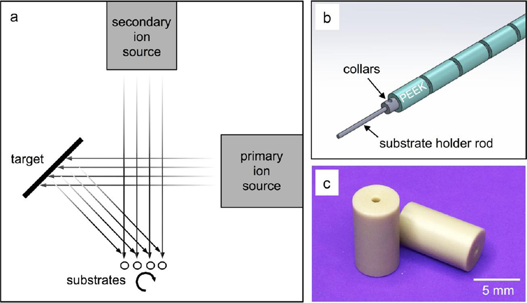
Deposition of the HA/YSZ coatings was achieved by way of a custom rotational substrate fixture and an IBAD system (Univex 600, Oerlikon Leybold Vacuum). The deposition system is composed of 8-in diameter HA and YSZ targets (Plasmaterials, Inc) with 16-cm primary and 12-cm secondary ion sources outfitted with argon process gas. The deposition process within the IBAD system is shown in Figure 1a. Figure 1b shows the custom substrate fixture that was developed to mount cylindrical PEEK substrates (Figure 1c) on rotating titanium rods with retaining collars to ensure even coating during deposition. Adjustable-speed simultaneous rotation was achieved by way of a water-cooled gearbox and an external feed-through stepper motor. The deposition parameters were optimized for film thickness and density. Secondary ion energies were initially elevated and gradually reduced throughout the deposition period; substrate ion bombardment promotes atomic mixing at the interfacial zones but causes resputtering, detrimental to overall deposition rates. The base vacuum pressure achieved before deposition was approximately 6.7 × 10⁻⁵ Pa and the deposition pressure varied from 4 × 10⁻² to 6.6 × 10⁻² Pa depending on the primary and secondary ion source flow rates. The temperature near the deposition area was monitored during deposition and maintained well below the glass transition temperature of PEEK to avoid any damage to the polymer substrate. The deposition chamber was vented between YSZ and HA layer deposition to exchange sputtering targets. A similar process using a planar IBAD substrate holder was used to deposit coatings on flat PEEK substrates for adhesion strength testing. Deposition times for flat samples with single-layer YSZ or HA coatings were adjusted to achieve the same final coating thickness (1µm) as HA/YSZ coatings.
Figure 1.
Schematic of ion beam assisted deposition (IBAD) process (a). Detail of substrate retention mechanism including Ti mounting rod and retaining collars (b) for cylindrical PEEK substrates (c).
2.2 Post-deposition Heat Treatment
Selective heating of the coating was achieved using a variable frequency microwave oven (Microcure, Lambda Technologies) in order to aid in crystallization of the HA layer without damaging the underlying PEEK substrate. The microwave unit delivers power up to 400 W at a frequency range of 5.8 to 7 GHz to perform the heat treatment in accordance with the methods described in patent US8323722 [26]. Autoclave processing was also applied to some samples using a commercial sterilization unit (Prevac Steam Sterilizer, Steris). The temperature-programmable autoclave was adjusted to apply a saturated steam cycle of 136°C for 8 h.
2.3 Analysis of coatings
2.3.1 Uniformity
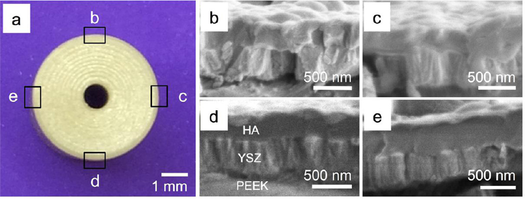
The microstructure of the as-deposited and heat-treated films was observed by scanning electron microscopy (SEM) using a high-resolution field emission unit (Verios 460L, FEI). Sectioning of the PEEK rod using a precision saw blade (Buehler) allowed analyzing the cross-section and radial measurement of the coating thickness to determine uniformity around the circumference of the cylindrical PEEK surface (Figure 2).
Figure 2.
a) Optical image of the cross-section of cylindrical PEEK sample; b-e) zoomed in SEM images of the cross section of the YSZ/HA coating at various locations around the PEEK implant circumference.
2.3.2 Adhesion strength
The adhesion strength between the coating and the flat PEEK substrate discs was analyzed by the pull-off test method performed with a breaking point testing machine and epoxy-coated studs (Romulus IV workstation, Quad Group). Determination of the adhesion strength on a curved surface is troublesome and can be inaccurate. Therefore, flat PEEK substrates were coated in parallel using similar surface preparation, deposition, and heat treatment parameters to cylindrical samples and the adhesion of the coating was measured. The studs were mounted normal to the coated sample surfaces with spring clips and the epoxy cured for 1 h at 150°C in a programmable furnace at atmosphere. Test specimens were allowed to air-cool at room temperature before testing to reach the cured epoxy strength rating (~70MPa). The mounting clips were removed and samples were mounted in the tester by the stud with instrument grips. A loading rate of 10 N/s was then used to apply axial force to the stud until it was separated from the sample surface. An optical microscope was used for observation of the coating surface to determine where the failure occurred. The interfacial strength between the coating and the substrate was calculated as the maximum force divided by the cross-sectional area of the stud. Triplicates were performed for each coating sample type: A single-layer HA coating on a rough machined PEEK surface, a single-layer YSZ coating on a smooth ground PEEK surface, and the two-layer HA/YSZ coatings as deposited (AD), HA/YSZ with microwave treatment (MW), and HA/YSZ with microwave followed by autoclave (MW+AC) all on smooth-ground PEEK surfaces.
2.3.3 Microstructure and chemical analysis
HA/YSZ samples were prepared for transmission electron microscopy (TEM) by focused ion beam (FIB) lift-out and thinning (Quanta 3D FEG, FEI) on coated cylindrical substrates. The crystallinity of the coating was observed by TEM (2010F, Jeol) and selected area diffraction (SAD). SAD patterns were indexed and analyzed with respect to powder diffraction standards (JCPDS). Energy dispersive spectroscopy (EDS) was used in conjunction with scanning tunneling microscope (STM) (Titan, FEI) on the cross section of the HA coatings to determine their chemical composition at various locations.
3. Results
3.1 Coating uniformity
The HA/YSZ coating thickness was measured at various locations around the circumferential PEEK surface to determine the deposition uniformity using the rotating substrate holder. Figure 2a shows a digital image of the cross section of a coated cylindrical PEEK substrate, while figures 2b–e show the zoomed in SEM images of the HA/YSZ coating on various locations around the substrate. A layer of crystalline YSZ and amorphous calcium phosphate can be seen in these figures on the cylindrical PEEK substrates in the as-deposited condition. The coating cross-section was measured three times at the indicated radial locations to obtain an average thickness. Local averages were compared between radial locations to determine coating uniformity and for calculating the grand average thickness. The results indicated a total average thickness of 780 ± 13nm with ± 2% radial uniformity. These results were then used to adjust deposition parameters to achieve a total coating thickness of 1 µm (500 nm YSZ, 500 nm HA) for the remaining analyses.
3.2 Coating Adhesion
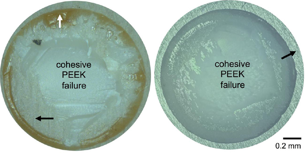
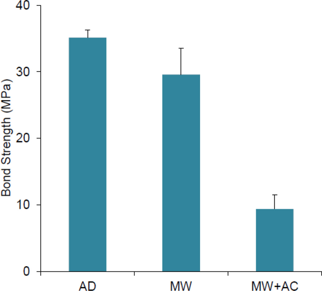
Table I shows the results of the bond strength testing for each coating type. The adhesion strength of a 1-µm HA layer deposited on a rough, machined PEEK surface was 73 MPa. A similar 1-µm YSZ layer on a smooth, polished PEEK surface recorded lower bond strength of 59 MPa, indicating the effect of surface roughness on coating’s bond strength. Optical microscopy images of the adhesion test site on both types of smooth and rough PEEK samples coated with single layer of HA or YSZ are shown in Figure 3. As can be seen in these figures, the failure mostly occurred within the PEEK itself (PEEK cohesive failure), with some additional epoxy failure present on the rough, machined PEEK sample. The adhesion strength of the two-layer HA/YSZ coatings was lower than either of the single-layer coatings. A comparison of the HA/YSZ coatings’ adhesion strength is shown in Figure 4. The average adhesion strength was found to be 35 MPa for AD HA/YSZ coatings, and 30 MPa for MW treated samples. A decrease in the adhesion strength to ~10 MPa was observed after subsequent autoclave treatment (MW+AC). Observation of the adhesion test area on HA/YSZ coated samples indicated some degree of failure at the HA-YSZ interface due to the mismatch of the coefficient of thermal expansion between the two coating layers. Table II shows the stud pull bond strength of HA coatings on PEEK substrates from this study compared with what is reported in the literature. The results show that the HA/YSZ coatings deposited by IBAD exhibit higher adhesive strength than that reported for other deposition methods on PEEK. Single layer coatings of HA on PEEK approach those reported for IBAD on titanium substrates [27,28].
Table I.
Adhesion strength of coatings on PEEK.
| HA only | YSZ only | HA/YSZ AD |
HA/YSZ MW |
HA/YSZ MW+AC |
|
|---|---|---|---|---|---|
| Adhesion Strength (MPa) |
*73 ± 3 | *59 ± 8 | 35 ± 1 | 30 ± 4 | 9 ± 2 |
(*) indicates cohesive PEEK failure. Machined PEEK surfaces are labeled rough.
Figure 3.
Adhesion strength test site showing failure modes of single layer coated PEEK substrates. Optical microscope images of rough machined surfaces (left) and smooth prepared surfaces (right). Black arrows indicate machining marks (right) and polishing marks (right); white arrow shows cohesive epoxy failure.
Figure 4.
Adhesion strength of AD as-deposited, MW microwave annealed, MW+AC microwave treatment plus autoclaving HA/YSZ coatings prepared by IBAD on smooth PEEK surfaces.
Table II.
Adhesion strength of hydroxyapatite coatings on PEEK substrates by various deposition techniques as measured by pull-off testing.
3.3 Microstructural analysis and crystallinity
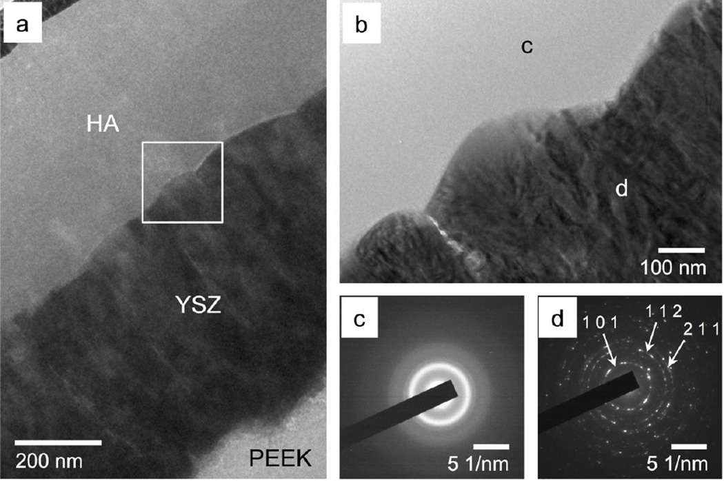
Figure 5 shows the 1-µm AD coating as observed by TEM. The YSZ-PEEK interface shows no voids or delamination, indicating good coating adhesion. The YSZ layer appears dense and fully crystalline with a visible columnar grain structure oriented perpendicular to the substrate surface (Figure 5a). The calcium phosphate layer does not exhibit any voids and appears amorphous with no crystalline contrast across its thickness and the HA-YSZ interface shows no delamination between coating layers (Figure 5b). The SAD pattern of the YSZ layer (Figure 5d) indicates that the layer is polycrystalline along (1 0 1), (1 1 2), (2 1 1) planes, which is in good agreement with YSZ lattice spacing provided by JCPDS standards. The SAD pattern of the HA layer shown in Figure 5c confirms that the calcium phosphate is amorphous in its as-deposited state.
Figure 5.
TEM observation of the as-deposited HA/YSZ coating (a), zoomed in interface area marked by a white square in 5-a (b), SAD patterns of HA layer (c) and SAD patterns of YSZ layer (d)
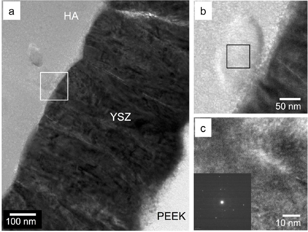
TEM observation of the MW treated sample is shown in Figure 6. High magnification of the HA-YSZ interface shows no delamination with a crystalline structure observed in various locations throughout the HA layer (Figure 6a–b). The orientation of the crystal grain is observed in the high-resolution TEM (HRTEM) image, and fast Fourier transform (FFT) analysis confirmed the crystallinity of the observed region (Figure 6c).
Figure 6.
TEM observation of the microwave-annealed HA/YSZ coating (a), zoomed in interface area marked by a white square in 6-a showing crystalline structures (b). HRTEM image of HA marked by black square in 6-b (c) and FFT pattern (inset) of crystalline HA region.
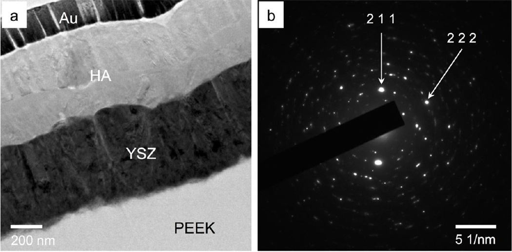
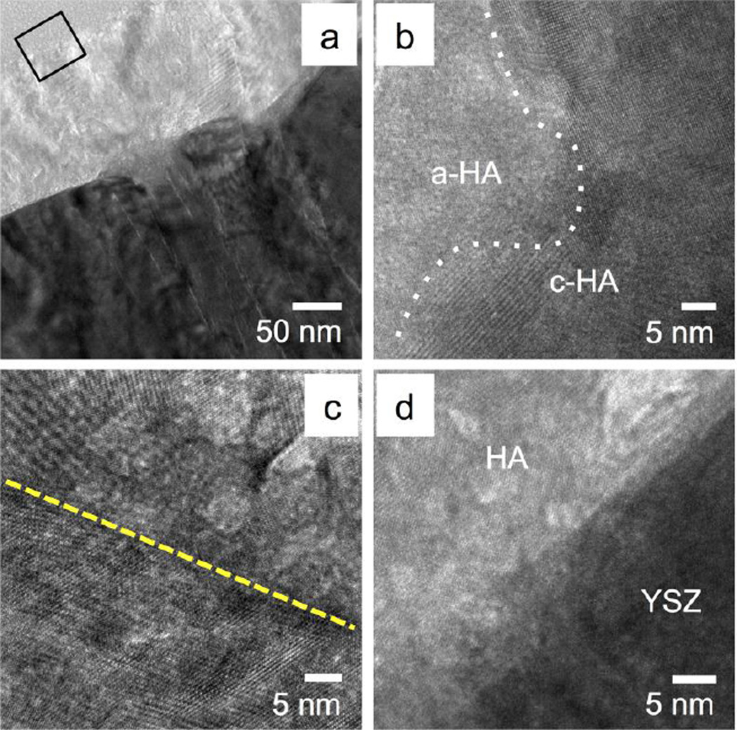
Figure 7a shows the TEM image of the MW+AC sample. No delamination or voids were observed in the sample cross-section. The YSZ exhibited the same columnar crystal grain structure as both the AD and MW samples, while the HA layer exhibited further crystallization after subsequent autoclave treatment. Crystalline morphology is observed at the top of the HA layer and at the HA-YSZ interface in the TEM images. A small zone of amorphous calcium phosphate is also visible near the middle of the layer. The SAD pattern of the HA layer in Figure 7b confirms the presence of crystalline HA (2 1 1) and (2 2 2) in good agreement with JCPDS standard lattice spacing. Figure 8a shows the MW+AC coating in greater detail, revealing a clear region of amorphous calcium phosphate atop the crystalline HA structure near the HA-YSZ interface. HRTEM Observation of the HA layer shows the crystalline-amorphous boundary and crystal grains in the MW+AC sample (Figure 8b). HRTEM of a grain boundary within the crystalline region of the sample is shown in Figure 8c, indicating random crystal orientation. The HA-YSZ interface is also observed under HRTEM in Figure 8d, showing good atomic mixing in the interfacial zone.
Figure 7.
TEM observation of the microwave plus autoclave treated HA/YSZ coating on PEEK (a), with and SAD pattern of the HA layer (b).
Figure 8.
HRTEM observation of the microwave plus autoclave treated HA/YSZ coating on PEEK (a), zoomed in area marked by a black square in 8-a showing distinct amorphous calcium phosphate (a-HA) and crystalline (c-HA) hydroxyapatite regions (b). HA grain boundaries (dashed line) within the polycrystalline HA region (c), and atomic mixing due to secondary ion bombardment at the HA/YSZ interface (e).
3.4 Chemical composition
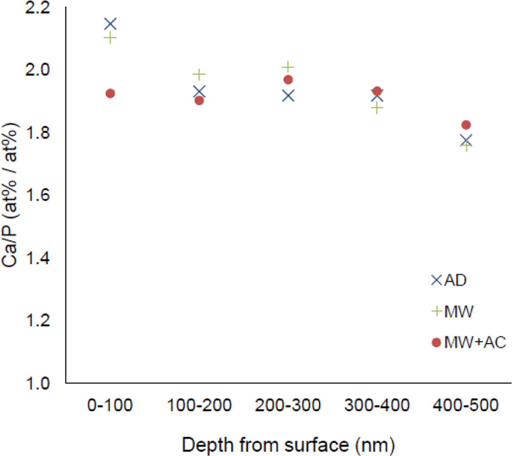
EDS mapping of the HA layer was performed for each of the HA/YSZ coated sample groups (AD, MW, MW+AC) to determine the chemical composition of the coatings. The EDS maps of the HA layer were then split into five regions across the thickness to observe any compositional changes through the coating cross-section. The results are shown in Figure 9 in terms of the Ca/P ratio from the top of the HA layer (0 nm) to the HA-YSZ interface (500 nm). In AD and MW samples the highest Ca/P ratio occurred at the coating surface, and the lowest Ca/P ratio occurred near the HA-YSZ interface for all samples. In the case of the MW+AC sample, the surface Ca/P ratio was lower than AD or MW samples. The overall average Ca/P ratios for AD, MW and MW+AC samples were 1.94, 1.95 and 1.91, respectively.
Figure 9.
Calcium to phosphate ratio of as-deposited (AD), microwave annealed (MW), and microwave plus autoclave (MW+AC) coating samples.
4. Discussion
Coating uniformity is an important aspect of any deposition technique, and is essential for commercial production. In this study, the SEM results indicate that cylindrical PEEK substrates were evenly coated with HA/YSZ (± 2% radial uniformity), as determined by thickness measurements of the cross-section at various radial locations. This demonstrates the successful design and operation of a novel substrate holder for applying uniform coatings via IBAD to non-planar surfaces. The thickness, crystallinity and microstructure of the calcium phosphate layer are important factors controlling the lifetime and performance of bioactive coatings in the body. The dissolution properties of thin layers of calcium phosphate have been reported in the literature [29], showing that crystalline HA exhibits much slower dissolution; 90% of a crystalline HA coating thickness remained after 35 days in simulated body fluid (SBF) compared to 15% for amorphous calcium phosphate [29]. This demonstrates the capability of crystalline HA coatings to produce prolonged osteoconductive properties during the healing process. The dense, pore-free nature of the coatings deposited by IBAD is expected to further extend the lifetime of the crystalline HA layer in the body; in vitro results support prolonged bioactivity with the implementation of HA/YSZ coatings [25]. An ongoing in vivo study in a rabbit model will provide additional information about the long-term biological response to coated implants, which will be reported in our upcoming publications.
The YSZ coating exhibited a columnar crystalline structure after deposition while the calcium phosphate layer was completely amorphous. Both layers showed dense coating layers without voids or porosity and good interfacial bonding. Subsequent heat treatment of the calcium phosphate layer resulted in nucleation and growth of crystalline HA structures as evident by TEM observation of the microwave treated and the microwave plus autoclave treated samples. In particular, microwave heat treatment caused crystalline nucleation and growth at various locations in the calcium phosphate layer. Additional autoclaving expanded crystallization throughout the calcium phosphate layer. It is noteworthy that the underlying YSZ surface creates nucleation sites for crystal formation at the HA-YSZ interface as soon as enough energy is provided via microwave or autoclave processing. Samples that undergo crystallization via microwave treatment appear to experience additional crystal growth during subsequent autoclave treatment. High resolution TEM and SAD pattern analysis indicated random crystal orientation and polycrystalline structure within the HA regions of heat-treated coatings (Figures 6 & 7). Comparison of the YSZ-PEEK and HA-YSZ interfaces of all samples by TEM showed that heat treatment did not cause delamination of the coating from the substrate, a pre-requisite for all successful implants.
The single-layer HA and YSZ coatings on PEEK revealed the strongest adhesion of the coatings tested. Cohesive failure within the polymer and the pull stud epoxy demonstrates the ability to achieve very strong adhesion to PEEK using IBAD, and that the true adhesion strength of the coating approaches that of the cohesive bonding within PEEK itself. The results agree well with those reported for HA coatings deposited by IBAD on titanium [27,28]. Coatings deposited on rough surfaces exhibited the highest adhesion strength, consistent with other reports in the literature [30]. The HA/YSZ coatings were prepared on smooth surfaces to study the individual effects of IBAD deposition and various heat treatments on the adhesion strength. Results showed that the adhesion of HA/YSZ coatings was below that of single-layer coatings, with failure often occurring at the HA-YSZ interface. The uniform deposition achieved using IBAD allows surface roughness to translate through coating layers, and is expected to improve the adhesion strength of HA/YSZ coatings by enhancing mechanical interlocking between layers. Preliminary findings demonstrated an increase in the adhesion strength of as-deposited HA/YSZ coatings from 35 MPa on smooth PEEK to 42 MPa on surfaces ground against 320-grit paper before deposition. The adhesion strength results on various samples indicate that heat treatment of the HA layer by microwave had little effect on coating adhesion due to the microwave transparency of PEEK and the presence of the YSZ thermal barrier coating layer. Subsequent autoclave treatment resulted in decreased adhesion strength; hydrothermal treatment heats the entire sample, increasing residual stresses at the interface of various layers due to the mismatch of coefficient of thermal expansion between the PEEK, YSZ and HA. These additional residual stresses lower the adhesion strength of the coating, making autoclaving an undesirable heat treatment for HA on PEEK.
Investigation of the coating’s chemical composition shows that the Ca/P ratio of the deposited coatings is slightly higher than that of stoichiometric HA (1.67), consistent with other reports of sputtered HA coatings [31,32]. Microwave heat treatment did not have a major affect on the Ca/P ratio of the HA layer, however, it was noted that samples that underwent microwave heat treatment and additional autoclaving exhibited a lower Ca/P ratio near the top surface than other samples. The reduced Ca/P ratio is likely due to the dissolution of CaO from the coating surface as observed previously with hydrothermal processing of hydroxyapatite films [21]. Nevertheless, the heat-treated coating samples prepared by IBAD showed the formation of crystalline HA with desirable chemical composition for use as biomedical implant coatings.
5. Conclusions
In this study, cylindrical PEEK substrates were coated with HA/YSZ using ion beam assisted deposition (IBAD) at room temperature. IBAD proved to be an effective deposition method for evenly applying calcium phosphate coatings to non-planar substrates with high uniformity. The calcium phosphate coating layer was then successfully crystallized by heat treatment. High-resolution microstructural analysis showed that microwave heat treatment crystallized HA without lowering the bond strength of the coating, while the subsequent autoclave treatment further expanded crystal growth but lowered the bond strength of the coating to PEEK substrates. Microwave heat treatment followed by autoclaving reduced the Ca/P ratio slightly at the surface–closer to stoichiometric HA. The pull-off test results indicated the potential for increasing coating strength with additional surface roughness of the substrate and can be used in combination with IBAD to further optimize bioactive HA/YSZ coatings to enhance bone growth and osseointegration for implantable PEEK biomaterials.
Highlights.
Uniform multilayer coatings are deposited on cylindrical polyetheretherketone
Coatings prepared by ion beam assisted deposition have high adhesion strength
Microwave and hydrothermal heat treatments crystallized the hydroxyapatite layer
Yttria-stabilized zirconia layer provides a thermal barrier for PEEK
Acknowledgments
The research reported in this publication was supported by the National Institute of Dental and Craniofacial Research of the National Institutes of Health under award number R21DE022925. The content is solely the responsibility of the authors and does not necessarily represent the official views of the National Institutes of Health.
Footnotes
Publisher's Disclaimer: This is a PDF file of an unedited manuscript that has been accepted for publication. As a service to our customers we are providing this early version of the manuscript. The manuscript will undergo copyediting, typesetting, and review of the resulting proof before it is published in its final citable form. Please note that during the production process errors may be discovered which could affect the content, and all legal disclaimers that apply to the journal pertain.
References
- 1.Ramakrishna S, Mayer J, Wintermantel E, Leong KW. Biomedical applications of polymer-composite materials: a review. Compos. Sci. Technol. 2001;61:1189–1224. [Google Scholar]
- 2.Kurtz SM, Devine JN. PEEK Biomaterials in Trauma, Orthopedic, and Spinal Implants. Biomaterials. 2007;28:4845–4869. doi: 10.1016/j.biomaterials.2007.07.013. [DOI] [PMC free article] [PubMed] [Google Scholar]
- 3.Godara A, Raabe D, Green S. The influence of sterilization processes on the micromechanical properties of carbon fiber-reinforced PEEK composites for bone implant applications. Acta Biomater. 2007;3:209–220. doi: 10.1016/j.actbio.2006.11.005. [DOI] [PubMed] [Google Scholar]
- 4.Toth JM, Wang M, Estes BT, Scifert JL, Seim HB, III, Turner AS. Polyetheretherketone as a biomaterial for spinal applications. Biomaterials. 2006;27:324–334. doi: 10.1016/j.biomaterials.2005.07.011. [DOI] [PubMed] [Google Scholar]
- 5.Ferguson SJ, Visser JMA, Polikeit A. The long-term mechanical integrity of non-reinforced PEEK-OPTIMA polymer for demanding spinal applications: experimental and finite-element analysis. Eur. Spine J. 2005;15:149–156. doi: 10.1007/s00586-005-0915-5. [DOI] [PMC free article] [PubMed] [Google Scholar]
- 6.Martin BI, Mirza SK, Comstock BA, Gray DT, Kreuter W, Deyo RA. Reoperation Rates Following Lumbar Spine Surgery and the Influence of Spinal Fusion Procedures: Spine. 2007;32:382–387. doi: 10.1097/01.brs.0000254104.55716.46. [DOI] [PubMed] [Google Scholar]
- 7.Ma R, Tang T. Current Strategies to Improve the Bioactivity of PEEK. Int. J. Mol. Sci. 2014;15:5426–5445. doi: 10.3390/ijms15045426. [DOI] [PMC free article] [PubMed] [Google Scholar]
- 8.Briem D, Strametz S, Schröoder K, Meenen NM, Lehmann W, Linhart W, et al. Response of primary fibroblasts and osteoblasts to plasma treated polyetheretherketone (PEEK) surfaces. J. Mater. Sci. Mater. Med. 2005;16:671–677. doi: 10.1007/s10856-005-2539-z. [DOI] [PubMed] [Google Scholar]
- 9.Zhao Y, Wong HM, Wang W, Li P, Xu Z, Chong EYW, et al. Cytocompatibility, osseointegration, and bioactivity of three-dimensional porous and nanostructured network on polyetheretherketone. Biomaterials. 2013;34:9264–9277. doi: 10.1016/j.biomaterials.2013.08.071. [DOI] [PubMed] [Google Scholar]
- 10.Khoury J, Kirkpatrick SR, Maxwell M, Cherian RE, Kirkpatrick A, Svrluga RC. Neutral atom beam technique enhances bioactivity of PEEK. Nucl. Instrum. Methods Phys. Res. Sect. B Beam Interact. Mater. At. 2013;307:630–634. [Google Scholar]
- 11.Wang L, Weng L, Song S, Zhang Z, Tian S, Ma R. Characterization of polyetheretherketone–hydroxyapatite nanocomposite materials. Mater. Sci. Eng. A. 2011;528:3689–3696. [Google Scholar]
- 12.Wang L, He S, Wu X, Liang S, Mu Z, Wei J, et al. Polyetheretherketone/nano-fluorohydroxyapatite composite with antimicrobial activity and osseointegration properties. Biomaterials. 2014;35:6758–6775. doi: 10.1016/j.biomaterials.2014.04.085. [DOI] [PubMed] [Google Scholar]
- 13.LeGeros RZ. Biodegradation and bioresorption of calcium phosphate ceramics. Clin. Mater. 1993;14:65–88. doi: 10.1016/0267-6605(93)90049-d. [DOI] [PubMed] [Google Scholar]
- 14.de Groot K, Geesink R, Klein CP, Serekian P. Plasma sprayed coatings of hydroxylapatite. J. Biomed. Mater. Res. 1987;21:1375–1381. doi: 10.1002/jbm.820211203. [DOI] [PubMed] [Google Scholar]
- 15.Hahn B-D, Park D-S, Choi J-J, Ryu J, Yoon W-H, Choi J-H, et al. Osteoconductive hydroxyapatite coated PEEK for spinal fusion surgery. Appl. Surf. Sci. 2013;283:6–11. [Google Scholar]
- 16.Almasi D, Izman S, Assadian M, Ghanbari M, Abdul Kadir MR. Crystalline ha coating on peek via chemical deposition. Appl. Surf. Sci. 2014;314:1034–1040. [Google Scholar]
- 17.Barkarmo S, Wennerberg A, Hoffman M, Kjellin P, Breding K, Handa P, et al. Nano-hydroxyapatite-coated PEEK implants: A pilot study in rabbit bone. J. Biomed. Mater. Res. A. 2013;101A:465–471. doi: 10.1002/jbm.a.34358. [DOI] [PubMed] [Google Scholar]
- 18.Lee JH, Jang HL, Lee KM, Baek H-R, Jin K, Hong KS, et al. In vitro and in vivo evaluation of the bioactivity of hydroxyapatite-coated polyetheretherketone biocomposites created by cold spray technology. Acta Biomater. 2013;9:6177–6187. doi: 10.1016/j.actbio.2012.11.030. [DOI] [PubMed] [Google Scholar]
- 19.Rabiei A, Sandukas S. Processing and evaluation of bioactive coatings on polymeric implants. J. Biomed. Mater. Res. A. 2013;101A:2621–2629. doi: 10.1002/jbm.a.34557. [DOI] [PubMed] [Google Scholar]
- 20.Wang L, Nancollas GH. Calcium Orthophosphates: Crystallization and Dissolution. Chem. Rev. 2008;108:4628–4669. doi: 10.1021/cr0782574. [DOI] [PMC free article] [PubMed] [Google Scholar]
- 21.Ozeki K, Aoki H, Masuzawa T. Influence of the hydrothermal temperature and pH on the crystallinity of a sputtered hydroxyapatite film. Appl. Surf. Sci. 2010;256:7027–7031. [Google Scholar]
- 22.Blalock T, Bai X, Rabiei A. A study on microstructure and properties of calcium phosphate coatings processed using ion beam assisted deposition on heated substrates. Surf. Coat. Technol. 2007;201:5850–5858. [Google Scholar]
- 23.Bai X, Sandukas S, Appleford MR, Ong JL, Rabiei A. Deposition and investigation of functionally graded calcium phosphate coatings on titanium. Acta Biomater. 2009;5:3563–3572. doi: 10.1016/j.actbio.2009.05.013. [DOI] [PubMed] [Google Scholar]
- 24.Rabiei A, Thomas B, Neville B, Lee JW, Cuomo J. A novel technique for processing functionally graded HA coatings. Mater. Sci. Eng. C. 2007;27:523–528. [Google Scholar]
- 25.Durham JW, III, Allen MJ, Rabiei A. Preparation, characterization and in vitro response of bioactive coatings on polyether ether ketone. JBMR-B. 2015 doi: 10.1002/jbm.b.33578. in press. [DOI] [PMC free article] [PubMed] [Google Scholar]
- 26.Rabiei A. Processing of biocompatible coating on polymeric implants. [accessed April 28, 2015];US8323722 B2. 2012 http://www.google.com/patents/US8323722.
- 27.Surmenev RA. A review of plasma-assisted methods for calcium phosphate-based coatings fabrication. Surf. Coat. Technol. 2012;206:2035–2056. [Google Scholar]
- 28.Mohseni E, Zalnezhad E, Bushroa AR. Comparative investigation on the adhesion of hydroxyapatite coating on Ti-6Al-4V implant: A review paper. Int. J. Adhes. Adhes. 2014;48:238–257. [Google Scholar]
- 29.Jansen JA, León B. Thin calcium phosphate coatings for medical implants. New York: Springer; c2009. http://catalog.lib.ncsu.edu/record/NCSU2385256. [DOI] [PubMed] [Google Scholar]
- 30.Wang Y-Y, Li C-J, Ohmori A. Influence of substrate roughness on the bonding mechanisms of high velocity oxy-fuel sprayed coatings. Thin Solid Films. 2005;485:141–147. [Google Scholar]
- 31.Wolke JGC, van Dijk K, Schaeken HG, de Groot K, Jansen JA. Study of the surface characteristics of magnetron-sputter calcium phosphate coatings. J. Biomed. Mater. Res. 1994;28:1477–1484. doi: 10.1002/jbm.820281213. [DOI] [PubMed] [Google Scholar]
- 32.Ong JL, Lucas LC, Raikar GN, Weimer JJ, Gregory JC. Surface characterization of ion-beam sputter-deposited Ca-P coatings after in vitro immersion. Colloids Surf. Physicochem. Eng. Asp. 1994;87:151–162. [Google Scholar]


