Abstract
Employing 3D-printed templates for macro-to-micro interfacing, a passively operated polydimethysiloxane (PDMS) microfluidic device was designed for time-resolved secretion sampling from primary murine islets and epidiymal white adipose tissue explants. Interfacing in similar devices is typically accomplished through manually punched or drilled fluidic reservoirs. We previously introduced the concept of using hand fabricated polymer inserts to template cell culture and sampling reservoirs into PDMS devices, allowing rapid stimulation and sampling of endocrine tissue. However, fabrication of the fluidic reservoirs was time consuming, tedious, and was prone to errors during device curing. Here, we have implemented computer-aided design and 3D printing to circumvent these fabrication obstacles. In addition to rapid prototyping and design iteration advantages, the ability to match these 3D-printed interface templates with channel patterns is highly beneficial. By digitizing the template fabrication process, more robust components can be produced with reduced fabrication variability. Herein, 3D-printed templates were used for sculpting millimetre-scale reservoirs into the above-channel, bulk PDMS in passively-operated, eight-channel devices designed for time-resolved secretion sampling of murine tissue. Devices were proven functional by temporally assaying glucose-stimulated insulin secretion from <10 pancreatic islets and glycerol secretion from 2-mm adipose tissue explants, suggesting that 3D-printed interface templates could be applicable to a variety of cells and tissue types. More generally, this work validates desktop 3D printers as versatile interfacing tools in microfluidic laboratories.
Graphical Abstract Text Description
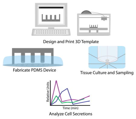
3D-printed templates were used for sculpting design-specific fluidic reservoirs into the above-channel bulk substrate of microfluidic devices, and these reservoirs were used for customized culture and time-resolved secretion sampling of murine islets and adipose tissue explants.
Introduction
Microfluidic devices offer many advantages over traditional fluidic devices such as reduced sample volume, ease of use, lower costs, and portability.1,2 Recent breakthroughs in cellular co-culture and organ-on-a-chip platforms have substantiated claims that the scale of microfluidic systems is well-matched with that of organized biological tissues.3,4 As shown by our group and others, microfluidic devices permit unique and valuable approaches for hormone secretion sampling, particularly from small amounts of endocrine tissue.5–9 These devices provide significant advantages over standard techniques by not only enhancing temporal resolution, but also by permitting assays on very small amounts of endocrine tissue.10 With primary tissue, this translates to more studies on fewer animals.
In standard microfluidic practice using PDMS devices, issues even as fundamental as interfacing tubing for flow control require manual punching of the substrate, with hand insertion of individual tubes.11 We have previously shown that rigid polymer templates are functional as moulds for fluidic reservoirs in passive, monolithic PDMS microdevices designed for endocrine tissue sampling.5,12 This work has highlighted the potential gains in device function that are available by extending patterning into the PDMS substrate above the channels, beyond the typical manual punching or drilling of reservoirs. Particularly for on-chip tissue culture, this bulk PDMS sculpting approach permits unique macro-to-micro interfacing that can be customized to the application or cell type. We demonstrated that a sequential decrease in reservoir size permitted rapid (<15 s) stimulation of pancreatic islets in a continuous flow setting with simple pipetting, yet without disturbing the cells.12 In another study, the challenge of culturing buoyant primary adipocytes on-chip was addressed using custom fluidic moats for 3D culture in collagen.5 However, these polymer templates were hand-constructed, increasing fabrication time as well as batch-to-batch variability. The templates required manual alignment with the photo-patterned wafer prior to PDMS curing, and failures were often encountered during transfer to an oven for curing, when templates would shift out of alignment with channels or even topple over into the uncured PDMS. These drawbacks point to a clear need for more robust and automated procedures for interface template fabrication.
Although 3D printers are widely used, high costs, resolution limitations, and printing medium properties have limited their adoption as commonplace microfluidic instruments.13,14 While printing of complete microfluidic devices is possible with high resolution printers, the cost of printers with resolution in the tens of micrometers still exceeds the price range for a typical research laboratory or small company.14–20 Additionally, many of the printers capable of printing moderately well resolved microfluidic devices utilize printing materials that are not as optimal or biocompatible as PDMS (i.e. loss of gas permeability, loss of transparency, non-biocompatible).20–22 Micro stereo lithography (MS) printers are becoming more affordable (below $2500) and also maintain reasonable printing resolutions (~50 μm laterally and 50 μm vertically). It has been previously established that microfluidic device templates can be printed on MS printers; however, it was shown that PDMS does not effectively cure around this printing resin. Additional steps must be taken using specialized airbrushing equipment to properly prepare the template for soft lithography.19,20 More affordable printers (below $2500) can now be purchased with layer resolution (z-direction) less than 50 μm and spatial resolution in the hundreds of micrometers.19,21 While 3D prints on this scale are inadequate for fabrication of more traditional microfluidic devices (channels with 10 – 50 μm widths), they should be ideal for well resolved millimetre-scale fluidic interfaces.
Herein, we employ computer-aided design and 3D printing (i.e. additive manufacturing) to address the need for more robust macro-to-micro interface fabrication in PDMS devices designed for endocrine tissue culture and sampling. 3D-printed interface templates are precisely matched in silico with channel patterns made by photolithography, and design iterations could be quickly tested with the advantage of rapid prototyping. Issues such as alignment and chip operation are further improved through the incorporation of novel 3D-printed support components. PDMS microfluidic devices made with these 3D-printed interfacing techniques were proven functional for temporal stimulation and secretion sampling from small amounts of primary murine tissue, specifically pancreatic islets and adipose explants. With flexibility in design, these 3D templated tissue culture interfaces should be applicable to a variety of cells and tissue types. More generally, this report validates a role for desktop 3D printers as primary tools in microfluidics laboratories for the purpose of precision interfacing from the laboratory scale to micrometre-scale channels in PDMS substrates.
Experimental Design
Materials
Insulin, D-glucose, 4-2-hydroxyethyl-1-piperazineethane-sulfonicacid (HEPES), nystatin, fluorescein, tetrahydrofuran (THF), KH2PO4, and NaH2PO4 were purchased from Sigma-Aldrich (St. Louis, Missouri). Bovine serum albumin (BSA), fetal bovine serum (FBS), NaCl, CaCl2·2H2O, and blunt ended needles were purchased from VWR (West Chester, Pennsylvania). Penicillin-streptomycin, Minimal Essential Media (MEM) non-essential amino acids solution 100X, sodium pyruvate, L-glutamine, and Dulbecco’s Modified Eagle Medium (DMEM), MgSO4·7H2O, was purchased from ThermoFisher Scientific (Grand Island, New York).
Interface template design, fabrication, and characterization
3D parts were modelled in Sketchup© (Trimble Navigation Limited) and all 3D printing was performed with the Makerbot Replicator 2 (100 μm layer resolution in z-direction) using Makerbot’s polylactic acid filament (PLA, 1.75mm diameter). When appropriate, surface smoothing of the printed objects was accomplished via exposure to THF vapour. 30 mL of THF was poured into a glass dish and heated to 80 °C while covered. Printed objects were attached to a secondary lid via copper wire. Once the THF condensation level reached the top 25% of the dish, the lids were exchanged allowing the 3D-printed objects to be suspended just above the liquid THF, where they were kept under THF vapour for 60 s. After treatment, pieces were rinsed with ddH2O and allowed to degas for approximately 60 min at room temperature before use.
For surface characterization of the 3D-printed objects, 10 × 10 × 5 mm3 test pieces were printed. Control pieces were left untreated, while test pieces were treated with THF as previously described. After rinsing and degassing of the pieces, both were cured into a batch of PDMS. Once cured, the test pieces were removed from the PDMS, and the impressions of the templates were analysed. Cross-sections of the impressions were sliced with a razor blade and mounted onto a glass microscope slide. Images were captured on a Nikon Ti-E inverted fluorescence microscope at 10X magnification, operating in wide-field transmittance mode.
Microfluidic design and fabrication
Microchip channel design was conducted on Adobe Illustrator, and these files were sent to Fineline Imaging (Colorado Springs, Colorado) for printing of negative photomasks (65,024 DPI). Using SU-8 photoresist (Microchem, Newton, Massachusetts), standard photolithographic methods were applied to silicon wafers in order to fabricate a master wafer for the microfluidic channels. Silicon wafers (Silicon, Inc., Boise, Idaho) were silanized with trimethylchlorosilane (TMCS) (Alpha Aesar) before moulding each batch of microchips through standard soft lithography using PDMS (Sylgard® 184; 10:1, base:curing agent). 3D-printed PLA templates were carefully aligned in the uncured PDMS before placement in an oven at 50 °C (below the PLA glass transition temperature of ~60–65 °C) for a minimum of 2 hours. After the PDMS fully cured, it was detached from the silicon wafer, and 3D-printed templates were removed.
In the eight-channel sampling device (Figure 1A), the distance from the central channel intersection to each channel outlet was 7.5 mm, with 50 μm channel widths and ~ 16 μm typical channel depths designed to passively control flow rates. Six 1.0-in2 designs (6.45 cm2) were fit into one 4.0-in diameter silicon wafer, generating a 2.0 inch by 3.0 inch (38.7 cm2) rectangular photo-patterned region. For parallel curing of six devices, silicon wafers were cut to leave only the 2.0 × 3.0 in2 rectangular channel designs. Small amounts of epoxy (5-minute set, Gorilla Glue) were applied to the bottom side of the wafer which was then gently placed into the wafer alignment container (see Figure 2A). Once the epoxy had set, wafers were silanized, and PDMS was added to the alignment container. 3D-printed interface templates (made of PLA) were simply snapped into place on the container and allowed to cure at 50 °C for a minimum of 2 h. Interface templates were then removed from the box, followed by the PDMS moulds. The PDMS substrate, patterned with both micrometre-scale channels and millimetre-scale fluidic interfaces, was then diced into individual devices, and each device was bonded irreversibly to glass floor substrates (glass microscope slides) using a plasma cleaner (Harrick Plasma). After incubation for at least 1 h in BSA-containing buffer for surface passivation, devices, such as the one shown in Figure 1B, were then ready for cell culture, stimulation, and sampling applications.12
Figure 1.
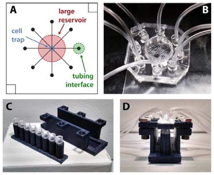
Microfluidic device design and interfacing for endocrine tissue stimulation and sampling. A) 8 channel microfluidic design. For clarity, only one channel output (green) is labelled. B) PDMS microfluidic chip with 3D-templated fluidic reservoir, cell trap, and PDMS plug-to-tubing interfaces. C) Disassembled and D) assembled 8-strip sample collection device. Each tube was interfaced with both a vacuum line and a sample line from the microchip to facilitate sequential temporal sampling.
Figure 2.
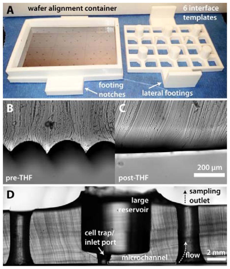
Fabrication of tissue and fluidic interfaces using 3D-printed templates. A) Image of a 3D-printed alignment container and a 6-well template for sculpting PDMS central reservoirs above SU-8 patterned microchannels. B) Cross-section of PDMS cured around an untreated 3D template and C) a template treated with THF vapours for 1 min. D) Cross-section of a typical PDMS microdevice. For clarity, only one microchannel sampling path is labelled.
Passive microfluidic flow control
For islet secretion sampling, samples were collected into reservoirs while simultaneously applying vacuum, resulting in a typical flow rate of ~40 μL h−1. First, 1.5 mm holes were punched through the centre of 3 mm PDMS plugs, and Tygon microbore tubing (0.508 ID × 1.524 mm OD; Cole-Parmer, Vernon Hills, Illinois) was inserted into the 1.5 mm holes. The plugs (with tubing) were then inserted into 3-mm diameter holes that were punched at the outlet of each channel. As depicted in Figure 1B, these plugs fit snugly into the outlets and were positioned a few centimetres from the bottom of the device to allow accumulation of secreted components into the reservoirs. Each time a new chip was used, the plugs were reinserted into the new microdevice.
For the larger sample volumes collected from adipose tissue explants (50 to 75 μL), secreted components were collected directly into the tubing and stored in PCR sample tubes. Eight separate pieces of tubing were directly interfaced to smaller (1.5-mm diameter) punched outlets at the end of each channel. Each of the 8 pieces of tubing was connected either directly to a syringe or to a custom 3D-printed vacuum manifold and collection device (Figure 1C; see ESI for more details). Manifolds were printed with a single opening for applying vacuum which was pneumatically linked to eight openings to connect tubing from the device. 1.5 mm tubing fit snugly into the manifold openings, but an airtight seal required addition of silicon caulk. 8-strip PCR sample tubes and a customized 3D-printed holder were used to collect the adipose tissue secretion samples. Strip lids were replaced by 3D-printed lids with vacuum and sample ports. 8-strip tubes were placed in a printed holder which was mechanically clamped to maintain an airtight seal between the 8 strip tubes and the printed lids. Sample tubings were interfaced directly to the ends of the microfluidic channels while the single vacuum tube was connected to the syringe. Vacuum was applied to the entire system, driving solution from the cell culture region, through the tubing, and into the PCR tubes for collection at a typical flow rate of ~110 μL h−1.
Channel crosstalk testing
During crosstalk tests, 50 nM and 100 μM fluorescein (in BMHH with 0.1% BSA) were used as low and high fluorescent tracers in the chip. Vacuum was applied to each channel in series, collecting solution for 5 min per channel. The first three samples were collected with 50 nM fluorescein in the cell culture reservoir. During the fourth sampling interval (20 min time point), 0.5 μL of 100 μM fluorescein solution was spiked near the channel input well. The remaining four samples were collected to test crosstalk between channel switching. Collected samples were analysed in 96-well plate format using a Beckman Coulter DTX 880 multimode microplate reader.
Pancreatic islet isolation and secretion sampling
Pancreatic islets were isolated from C57BL/6 male mice as described previously.23,24 After isolation, islets were placed in RPMI media (10% FBS, 11 mM glucose) at 37 °C and 5% CO2 to incubate overnight. Islets were then transferred from RPMI media to low glucose imaging media (3 mM) at 37 °C and allowed to acclimate for 1 h. Following the low glucose starve, islets were transferred to a microchip containing either low glucose imaging media (3 mM) or high glucose imaging media (11 mM). Vacuum was applied manually to each microchip channel for 5 minutes via a 100 mL glass syringe to achieve flow rates of ~40 μL h−1. After collecting sample for 40 min, tubing and plugs were removed from the outlet wells, and the sample volume was extracted using a pipette. Islet secretion samples were transferred from channel output wells to PCR tubes, diluted to 40 μL in BMHH, and stored at −20°C until quantification using a murine insulin ELISA kit (EZRMI-13K, Millipore).
Adipose explant isolation and secretion sampling
Epididymal white adipose tissue (eWAT) fat pads were removed from C57BL/6 male mice and placed in 37 °C phosphate-HEPES buffer, pH 7.3. Excess vasculature was excised from the tissue followed by cutting the fat pads into ~2 mm sections for explant culture. Explants were transferred into a centrifuge tube with fresh buffer and spun at 1000 rpm for 3 min. Infranatant was removed via 3 mL syringe fitted with an 18 gauge needle. This process was repeated twice more in phosphate-HEPES buffer. After the third buffer wash, explants were washed three additional times in Dulbecco’s Modified Eagle Medium (DMEM, 1.2% nystatin, penicillin/streptomycin, fetal bovine serum, and MEM nonessential amino acids). Individual explants were transferred into sterile wells in a 96-well plate containing 250 μL of fresh DMEM. Customized 3D-printed adipose tissue traps were placed in each well to counteract cell buoyancy and hold explants under the surface of the media. Explants were maintained in the plate at 37 °C and 5% CO2 until use.
Prior to microfluidic sampling, explants were washed in high glucose/high insulin buffer (HGHI; serum free DMEM, 19 mM glucose, 2 nM insulin) and then transferred into the inlet well on the microfluidic chip, which also contained HGHI. A 3D-printed adipose tissue trap was added to the reservoir to hold the explant in place on the chip while also allowing fluid flow. Vacuum was applied to each channel via a 60 mL syringe, resulting in flow rates of ~2 μL min−1. Explants were exposed to HGHI for 30 min, and secretions were collected in a single channel over this time period. Explants were then quickly washed, and bulk solution was replaced with low glucose/low insulin buffer (LGLI; serum free DMEM, 3.5 mM glucose, 50 pM insulin). LGLI-treated cell samples were collected every 10 min after the buffer change for 30 additional min. At the end of the sampling experiment, vacuum was removed, and samples were transferred to 1.7 mL collection tubes. Samples were stored in a freezer at −20 °C until quantification through glycerol assay kits (MAK117, Sigma). Samples were processed as per the manufacturer’s instructions for the fluorescent glycerol assay.
Results & Discussion
3D-printed interface templates
3D-printed interface template designs consisted of 6 reservoir-templating columns (for islets: 7.5 mm diameter; for adipose explants: 11.0 mm diameter), spaced to align over the centre of the 8-channel crossing points in each separate device on the wafer master (Figure 2A). Connected via a 2 × 3 in2 PLA rectangle with lateral footings, the columns were maintained 1.0 mm from the wafer surface. This 1.0 mm gap disconnected the fluidic reservoir region from the channels. Inlet ports could then be conveniently punched through the reservoir to the central channel crossings (islets: 1.5 mm, adipocyte explants: 3 mm). The inlet port served as a confinement chamber for the cells on the chip, as in our previous work.5,12 By sequestering the cells in a smaller chamber, bulk solution in the large reservoir could easily be changed without significant disturbance of the cells. Limiting the dead volume surrounding the cells allows for rapid exposure to stimuli as well as comprehensive sampling.12
In later iterations of the design, viewing ports were incorporated in the backing, and an interlocking system was designed to eliminate the need for hand alignment (Figure 2A). A base was included, with a 2 × 3 in2 region to insert and permanently bond the SU-8 patterned wafer. Wafers were cut to fit within the base dimensions. A removable wall with 9 mm height was printed to fit into the base and serve as the walls of a container for PDMS curing. Notched regions of the base allowed the PDMS templating piece to lock into place, which prevented movement of the templates as well as eliminating the need for hand alignment. All 3D designs are depicted in Electronic Supplementary Information (ESI), and the design files have been uploaded in STL and SKP format. A link to an online 3D repository is also included in ESI.
Template surface treatment
As shown by the cross-section of templated PDMS in Figure 2B, native 3D-printed parts retain grooved surfaces due to the layering process involved in fused deposition modelling, the most common mode of operation in desktop 3D printers. When necessary, THF treatments can be used to smooth the surface of the PLA material. Under controlled conditions, THF vapour partially dissolves the PLA surface, resulting in a smoothed surface that can serve as a template for PDMS (Figure 2C). While it is possible to cast PDMS with untreated PLA templates, THF-based surface smoothing improves the release process and eliminates the presence of excessive PDMS microstructures. All 3D-printed parts used herein were treated with THF vapours before use.
Fluidic interfacing for passive flow control
A cross-section of a typical device is shown in Figure 2D. For temporally-resolved sampling, devices were operated passively by serially applying vacuum to each of the 8 outlet channels. As discussed above, the method accommodates for sample collection for volumes less than 10 μL in the case of islet sampling on-chip; for the adipose tissue sampling, volumes averaged 20 μL, which was more easily collected and removed from directly connected tubing.
Akin to our previous work, this approach greatly simplifies the operation of the analytical system, using a hand-held syringe and exploiting inherent fluidic resistances of the microchannels for flow control.5,12 In this work, we used similar passive control and added the capability of temporally-resolved secretion sampling. Again, ease-of-use and device disposability are major advantages compared to other approaches that use syringe pumps or electroosmotic flow control. Devices were consequently inexpensive and disposable after a single use. Indeed, throughout this work, >30 devices were used for temporally-resolved secretion sampling, highlighting this advantage of operation simplicity that should be valuable to non-experts.
Evaluating channel crosstalk
It is well established that native PDMS is highly susceptible to non-specific adsorption of proteins and dyes such as fluorescein.25 In order to minimize this effect, all devices were pre-treated with BSA containing buffer to not only better mimic cell sampling conditions but also to function as a blocking mechanism for nonspecific binding of fluorescein during crosstalk tests. We have also previously shown this pre-treatment to effectively eliminate non-specific adsorption of proteins to PDMS channels and reservoirs, and this treatment is used in all biological experiments to follow.12
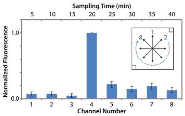
Since this 8-channel device was designed for simple, passive flow control, no valves were used to open or close the channels. It was thus necessary to evaluate the possibility of crosstalk between sampling channels during temporal sampling. Fluorescein solutions were used to track flow during operation of five separate devices. Operation of each device was matched with that of temporal sampling experiments, and solution was diverted from the central reservoir to a different outlet channel and reservoir every 5 min. Samples collected in outlet reservoirs were not removed for analysis until all 8 channels were tested, allowing evaluation of diffusive crosstalk during the runs. Figure 3 shows that fluorescence levels in the reservoirs sampled during the first 15 minutes (3 channels) were statistically equal to the 50 nM fluorescein standard (p > 0.1). Once vacuum was applied to the fourth sampling channel (20 min time point), 0.5 μL of 100 μM fluorescein was spiked into the cell chamber to mimic cellular release. As shown in Figure 3, this spike was observed in the expected outlet collection reservoir as a 16-fold increase in fluorescence signal. Samples collected at time points following the spike showed a 6-fold decrease from the maximum fluorescence, indicating residual amounts of concentrated fluorescein in the bulk solution. Fluorescence signals from these 4 final samples were statistically equal and did not show a decay curve response that would indicate carry-over.
Figure 3.
Channel crosstalk during time resolved sampling was determined as insignificant using fluorescein as a flow tracer (n = 5 devices). 50 nM fluorescein was added to the large central reservoir. 0.5 μL of 100 μM fluorescein was spiked into the smaller, cell-trap reservoir at the start of the 20 min sampling time to mimic cellular release. Inset channel design is labelled with channel numbers.
These results indicate minimal crosstalk during operation of the device and suggest that leakage through channels to outlets was insignificant. With all five devices, the 16-fold increase after the spike suggested that a large portion of the spiked fluorescein was swept into the appropriate collection channel (20-min collection). Any crosstalk after this spike would have exhibited a decay curve in subsequent samplings, which was not observed. Furthermore, passive leakage through the channels would have increased the fluorescence of the first three samples (5–15 min collections) above the 50 nM standard during the 40 min experiment, yet no such increase was observed. Overall, this experiment validated the passive, 8-channel device design as adequate for temporal sampling of cellular secretions without significant crosstalk. This validation experiment is further supported by cellular release profiles discussed in the sections that follow.
3D-printed adipose tissue traps
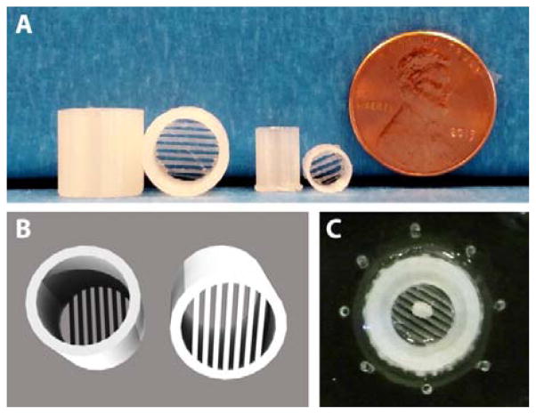
While tissues such as islets are denser than water and can be simply added to millimetre scale reservoirs as in Figure 2D, adipose tissue buoyancy poses a significant challenge for interfacing to microfluidic channels.5,6 We previously addressed this problem using hand-fabricated templates to create a moat where dispersed primary adipocytes could be anchored down in collagen, adjacent to sampling channels.5 In this work, adipose tissue explants were used, rather than dispersed adipocytes. This permitted the use of similar, albeit larger, interface designs compared to islet sampling devices. To counteract adipose tissue buoyancy, novel 3D-printed traps were designed and fabricated. Figure 4 shows the design and use of these customized adipose tissue trapping accessories. Due to the rapid prototyping capabilities, it was possible to quickly design custom traps for varying reservoir designs (Figure 4A) that were ideal for trapping 2-mm adipose tissue explants. As shown in the image (Figure 4A) and 3D renderings (Figure 4B), the traps included parallel beams of PLA (0.50 mm width, 0.50 mm spacing) that were suspended between the sides of the cylindrical support, which was custom fit to the reservoir size. These traps were used in the secretion sampling experiments to follow—a trapped explant is shown in Figure 4C—and they highlight the inherent flexibility of using customized 3D-printed templates and accessories for application to multiple classes of tissues.
Figure 4.
Adipose tissue buoyancy was counteracted using 3D-printed trapping accessories. A) Explant traps sized for microfluidic devices (leftmost two) and 96-well plates (middle two). B) 3D rendering of explant traps, with parallel beams of PLA (0.50 mm widths) designed to hold adipose explants. C) A 2 mm explant was sequestered well below solution level and into the smaller inlet port near microchannel inlets.
Time-resolved sampling of endocrine tissue
It is well known that increases in serum glucose levels in vivo trigger the release of insulin from pancreatic islets. Additionally, the levels of glucose and insulin have a profound effect on fat storage and release in adipose tissue. Interfacing of these two tissue types, islets and adipose, to microfluidic channels presents challenges that are fundamentally unique for each tissue. Accordingly, these tissues were considered ideal for validation of the flexibility of our method using 3D-printed interface templates.
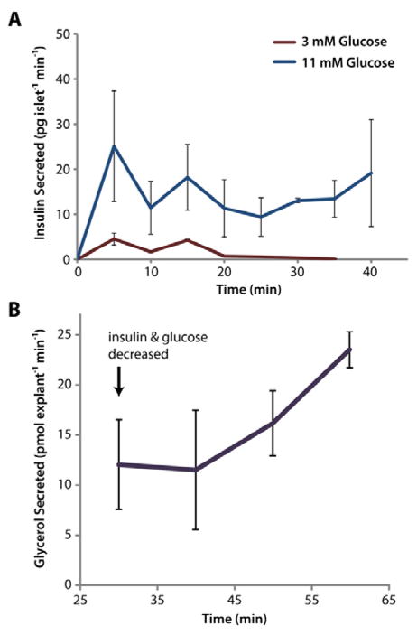
To monitor glucose-stimulated insulin secretion with our devices, groups of <10 islets were exposed to either 3 mM or 11 mM glucose, and secretions were sampled every 5 min by alternating vacuum between channels 1–8. As shown in Figure 5A, quantification of secreted insulin via immunoassay (ELISA) demonstrated that islets exposed to 11 mM glucose secreted insulin at significantly higher rates than those at basal glucose (p < 0.05), as expected. It is also noteworthy that this data provides further evidence for the lack of crosstalk between individual channels.
Figure 5.
3D-printed templates were used for microfluidic interfacing of two types of endocrine tissue for stimulation and temporal sampling. A) The insulin secretion rate from primary murine islets was clearly increased (p<0.05 for all points) in the presence of higher glucose levels, and the expected initial spike of insulin was observed. Five groups of <10 islets were assayed at high glucose, and two groups were assayed at low glucose (total of 7 microdevices used). B) Buoyant eWAT explants (2 mm) were trapped with 3D-printed accessories and interfaced to a 3D-templated device. After 30 min of treatment in HGHI solution, the explants were switched to LHLI solution, and the glycerol secretion rate was observed to increase, as expected. Three eWAT explants were evaluated on three separate microdevices.
To highlight the flexibility of the method, devices and accessories were also customized for adipose tissue interfacing to address cell buoyancy issues (see Figure 4 and discussion above). An 8-strip tube holder was likewise designed and 3D-printed for convenience in sample collection from the larger explants (see Figure 1C). To assay endocrine function, varying glucose and insulin levels were applied to these cells. Epididymal white adipose tissue (eWAT) explants were initially treated with HGHI to maximize triglyceride storage within lipid droplets in the cells. A single sample from this treatment was collected in one channel over 30 min to provide a baseline glycerol secretion rate. Once the explants were exposed to LGLI, samples were collected in 10-min intervals. As shown in Figure 5B, this treatment induced an increase in the glycerol release rate from the adipocytes after 20 min, signifying internal triglyceride breakdown. Glycerol release rates continued to increase after exposure to low insulin and glucose levels (LGLI), as expected. To our knowledge, this represents the first example of temporally-resolved microfluidic sampling of murine eWAT explants in the literature.
Conclusions
We have presented a robust method for macro-to-micro interfacing of endocrine tissue to microfluidic systems utilizing 3D-printed interface templates. Cylindrical templates were used to create millimetre scale fluidic reservoirs within the bulk PDMS substrate above microchannels. Fluidic interfaces and any necessary accessories could be customized to the tissue of interest. Resulting devices were validated for primary endocrine tissue sampling; glucose-stimulated insulin secretion was assayed from pancreatic islets, and glycerol secretion from adipocytes was sampled and quantified. The application to varying tissue types demonstrates the inherent flexibility of using 3D printing and rapid prototyping.
While the results herein are focused on passively-operated microfluidic devices, it is certainly feasible that similar 3D-printed interface templates could be used for interfacing fluidics and/or pneumatics to actively valved devices. By emphasizing the potential to sculpt bulk PDMS above microchannels using 3D-printed templates, this work also alludes to the possibility of interfacing other preparative or analytical techniques to microfluidic systems. For example, optical or electrical components could feasibly be integrated into the bulk PDMS to match with channel designs in a highly reproducible manner. Ultimately, these interfacing methods will be limited by the resolution of desktop 3D printers, but it is expected that a number of other applications could be devised.
Supplementary Material
Acknowledgments
Support for the work was provided by the National Institutes of Health (R01 DK093810) as well as by the Department of Chemistry and Biochemistry and the College of Science and Mathematics at Auburn University. The authors would like to thank Stephen Gass for his contributions to early design iterations of 3D-printed templates.
Footnotes
Electronic Supplementary Information (ESI) available: [details of any supplementary information available should be included here]. See DOI: 10.1039/x0xx00000x
Notes and references
- 1.McDonald JC, Duffy DC, Anderson JR, Chiu DT, Wu H, Schueller OJ, Whitesides GM. Electrophoresis. 2000;21:27–40. doi: 10.1002/(SICI)1522-2683(20000101)21:1<27::AID-ELPS27>3.0.CO;2-C. [DOI] [PubMed] [Google Scholar]
- 2.Sia SK, Whitesides GM. Electrophoresis. 2003;24:3563–76. doi: 10.1002/elps.200305584. [DOI] [PubMed] [Google Scholar]
- 3.Bhatia SN, Ingber DE. Nat Biotechnol. 2014;32:760–772. doi: 10.1038/nbt.2989. [DOI] [PubMed] [Google Scholar]
- 4.Byun CK, Abi-Samra K, Choi MY, Takayama S. Electrophoresis. 2013;35:245–257. doi: 10.1002/elps.201300205. [DOI] [PubMed] [Google Scholar]
- 5.Godwin LA, Brooks JC, Hoepfner LD, Wanders D, Judd RL, Easley CJ. Analyst. 2015;140:1019–25. doi: 10.1039/c4an01725k. [DOI] [PMC free article] [PubMed] [Google Scholar]
- 6.Dishinger JF, Reid KR, Kennedy RT. Anal Chem. 2009;81:3119–27. doi: 10.1021/ac900109t. [DOI] [PMC free article] [PubMed] [Google Scholar]
- 7.Adewola AF, Wang Y, Harvat T, Eddington DT, Lee D, Oberholzer J. J Vis Exp. 2010 doi: 10.3791/1649. [DOI] [PMC free article] [PubMed] [Google Scholar]
- 8.Yi L, Wang X, Dhumpa R, Schrell AM, Mukhitov N, Roper MG. Lab Chip. 2015;15:823–32. doi: 10.1039/c4lc01360c. [DOI] [PMC free article] [PubMed] [Google Scholar]
- 9.Mehling M, Tay S. Curr Opin Biotechnol. 2014;25:95–102. doi: 10.1016/j.copbio.2013.10.005. [DOI] [PubMed] [Google Scholar]
- 10.Easley CJ, Rocheleau JV, Head WS, Piston DW. Anal Chem. 2009;81:9086–95. doi: 10.1021/ac9017692. [DOI] [PMC free article] [PubMed] [Google Scholar]
- 11.Park J, Li J, Han A. Biomed Microdevices. 2010;12:345–51. doi: 10.1007/s10544-009-9390-9. [DOI] [PMC free article] [PubMed] [Google Scholar]
- 12.Godwin LA, Pilkerton ME, Deal KS, Wanders D, Judd RL, Easley CJ. Anal Chem. 2011;83:7166–72. doi: 10.1021/ac201598b. [DOI] [PMC free article] [PubMed] [Google Scholar]
- 13.Lee KG, Park KJ, Seok S, Shin S, Kim DH, Park JY, Heo YS, Lee SJ, Lee TJ. RSC Adv. 2014;4:32876. [Google Scholar]
- 14.Shallan AI, Smejkal P, Corban M, Guijt RM, Breadmore MC. Anal Chem. 2014;86:3124–30. doi: 10.1021/ac4041857. [DOI] [PubMed] [Google Scholar]
- 15.Gross BC, Erkal JL, Lockwood SY, Chen C, Spence DM. Anal Chem. 2014;86:3240–53. doi: 10.1021/ac403397r. [DOI] [PubMed] [Google Scholar]
- 16.Bhargava KC, Thompson B, Malmstadt N. Proc Natl Acad Sci U S A. 2014;111:15013–8. doi: 10.1073/pnas.1414764111. [DOI] [PMC free article] [PubMed] [Google Scholar]
- 17.Erkal JL, Selimovic A, Gross BC, Lockwood SY, Walton EL, McNamara S, Martin RS, Spence DM. Lab Chip. 2014;14:2023–32. doi: 10.1039/c4lc00171k. [DOI] [PMC free article] [PubMed] [Google Scholar]
- 18.Begolo S, Zhukov DV, Selck DA, Li L, Ismagilov RF. Lab Chip. 2014;14:4616–28. doi: 10.1039/c4lc00910j. [DOI] [PMC free article] [PubMed] [Google Scholar]
- 19.Comina G, Suska A, Filippini D. Lab Chip. 2014;14:424–30. doi: 10.1039/c3lc50956g. [DOI] [PubMed] [Google Scholar]
- 20.Yazdi AA, Popma A, Wong W, Nguyen T, Pan Y, Xu J. Microfluid Nanofluidics. 2016;20:50. [Google Scholar]
- 21.He Y, Wu Y, Fu J, Gao Q, Qiu J. Electroanalysis. 2016 [Google Scholar]
- 22.Bhattacharjee N, Urrios A, Kang S, Folch A. Lab Chip. 2016 doi: 10.1039/c6lc00163g. [DOI] [PMC free article] [PubMed] [Google Scholar]
- 23.Stefan Y, Meda P, Neufeld M, Orci L. J Clin Invest. 1987;80:175–83. doi: 10.1172/JCI113045. [DOI] [PMC free article] [PubMed] [Google Scholar]
- 24.Karl RC, Scharp DW, Ballinger WF, Lacy PE. Gut. 1977;18:1062–72. doi: 10.1136/gut.18.12.1062. [DOI] [PMC free article] [PubMed] [Google Scholar]
- 25.Toepke MW, Beebe DJ. Lab Chip. 2006;6:1484–6. doi: 10.1039/b612140c. [DOI] [PubMed] [Google Scholar]
Associated Data
This section collects any data citations, data availability statements, or supplementary materials included in this article.


