Abstract
In recent years, registration between x-ray fluoroscopy (XRF) and transesophageal echocardiography (TEE) has been rapidly developed, validated, and translated to the clinic as a tool for advanced image guidance of structural heart interventions. This technology relies on accurate pose-estimation of the TEE probe via standard 2D/3D registration methods. It has been shown that latencies caused by slow registrations can result in errors during untracked frames, and a real-time (> 15 hz) tracking algorithm is needed to minimize these errors. This paper presents two novel similarity metrics designed for accurate, robust, and extremely fast pose-estimation of devices from XRF images: Direct Splat Correlation (DSC) and Patch Gradient Correlation (PGC). Both metrics were implemented in CUDA C, and validated on simulated and clinical datasets against prior methods presented in the literature. It was shown that by combining DSC and PGC in a hybrid method (HYB), target registration errors comparable to previously reported methods were achieved, but at much higher speeds and lower failure rates. In simulated datasets, the proposed HYB method achieved a median projected target registration error (pTRE) of 0.33 mm and a mean registration frame-rate of 12.1 hz, while previously published methods produced median pTREs greater than 1.5 mm and mean registration frame-rates less than 4 hz. In clinical datasets, the HYB method achieved a median pTRE of 1.1 mm and a mean registration frame-rate of 20.5 hz, while previously published methods produced median pTREs greater than 1.3 mm and mean registration frame-rates less than 12 hz. The proposed hybrid method also had much lower failure rates than previously published methods.
Keywords: Real-time, GPGPU, 2D/3D registration, Cardiac interventions
1. Introduction
Image guidance is a key component of successful outcomes during catheter-based structural heart interventions. As more complex interventional cardiac procedures emerge, image guidance tools that can provide rapid and robust simultaneous visualization of devices and anatomy may be able to reduce intra- and post-procedural complications.
An example procedure is transcatheter aortic valve replacement (TAVR), where a prosthetic aortic valve is deployed via a catheter. During TAVR, both x-ray fluoroscopy (XRF) and transesophageal echocardiography (TEE) are used to image the heart. Positioning and deployment is mainly guided by XRF, while echo is typically relegated to an ancillary role (Kronzon et al., 2015). Despite having both imaging methods available to the operator, valve misalignment can occur resulting in catastrophic complications such as valve embolization, coronary artery occlusion or severe perivalvular regurgitation.
One of the main problems with XRF guidance during TAVR is the need for aortography to visualize the anatomy of the aortic root, which is critical for proper prosthetic valve positioning. Aortography requires the use of x-ray contrast dye, which is toxic to the kidneys and needs to be minimized in this vulnerable population. Real-time, continuous visualization of anatomical structures without the use of x-ray contrast may allow for more optimal positioning and deployment of the prosthetic valve without the risk of contrast dye-related kidney injury.
Recently, image registration between XRF and TEE has been validated (Housden et al., 2012) and clinically implemented (Philips EchoNavigator). This technology uses image processing to merge the XRF and echo coordinate systems, allowing for image information from both modalities to be fused into a single visualization framework. It is expected that image guidance during procedures such as TAVR can be improved using XRF/TEE registration by enabling workflows that allow echo to assume a larger role during the positioning and deployment of devices.
The workflow in Fig. 1 shows one possibility for merging anatomical information from echo with XRF. In this proposed scenario, the aortic annulus is segmented from the echo image in real-time, and then projected onto the XRF image. By utilizing anatomical information from echo, cardiorespiratory motion of the aortic root is compensated for without the use of x-ray contrast dye.
Fig. 1.
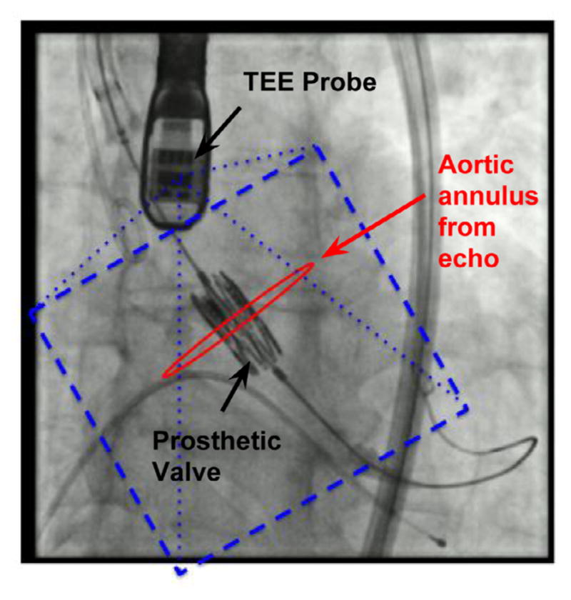
A potential workflow for TAVR enabled by real-time XRF/TEE registration and real-time anatomical segmentation. The aortic annulus is segmented in echo, and registered and displayed relative to a prosthetic valve.
To minimize positioning errors, such clinical workflows require algorithms that are accurate, have low rates of failure (i.e., are “robust”) and operate at frame-rates equal to or higher than imaging frame-rates. However, algorithms that meet these requirements without the need for complicated and expensive hardware modifications have proven to be elusive.
To address this issues, the contributions of this work are as follows: We first describe two novel registration algorithms, as well a hybrid method combining the two, designed for real-time 2D/3D registration of devices from XRF images. The first algorithm (DSC) was previously presented at MICCAI 2015 in Hatt et al. (2015c), while we introduce the second algorithm (PGC) in this work. In simulated and clinical datasets, we show that DSC greatly outperforms the prior state-of-the-art methods in terms of registration speed, operating at frame-rates as high as 100 hz. To the best of our knowledge this is the fastest 2D/3D registration algorithm reported in the literature, regardless of the application. Furthermore, DSC achieved lower failure rates than previously reported methods. PGC was also faster than earlier reported methods and similarly accurate. By combining both algorithms into a hybrid method, a solution with the lowest failures rates, highest accuracy, and fastest registration speed was achieved.
2. Previous work
Registration between XRF and TEE was first demonstrated using magnetic tracking sensors in Jain et al. (2009). The main problems were that extra hardware and modifications to the TEE probe were required, and that the system was prone to inaccuracies due to electromagnetic fields generated by the XRF system. Image based methods were first presented in Gao et al. (2010), where the feasibility of using GPU accelerated raycasting techniques to register the TEE probe to XRF images was demonstrated. The initial results indicated that the method was accurate (mean projection distance = 1.8 ± 1.13 mm), and fast enough for clinical applications that required sub-real-time registrations (1.8 ± 0.6 seconds per registration). The authors also found that cardiorespiratory motion caused projection errors up to 4 mm, and noted that a true real-time algorithm was necessary to overcome these errors. In follow-up work (Housden et al., 2012), the algorithm was implemented on a system that was able to stream echo and XRF data and display both modalities in a common coordinate system.
A different approach was taken in Lang et al. (2012), where radio-opaque fiducials were attached to the TEE probe to enable feature based registration, which allowed for faster (20 hz) and more accurate (1.20 ± 0.91 mm projection error) results. However, this could only be achieved through the addition of the external fiducials to the probe, which required a custom modification that could not easily be reproduced and may increase the risk of esophageal injury.
Machine learning based techniques have also been used (Mountney et al., 2012; Hatt et al., 2015a; Heimann et al., 2014) but have focused primarily on fully-automatic probe detection rather than 5DOF or 6DOF pose-estimation, which is necessary to achieve the accuracy required for most clinical applications.
3. Similarity metrics
The technical focus of this paper is on pose-estimation techniques that utilize 2D/3D registration, which is a technique used to estimate the 3D position and orientation of an object from 2D projection images. An exhaustive survey of the topic is found in Markelj et al. (2012). The standard workflow consists of 1) initialization of pose parameters (ϕ), 2) spatially transforming a 3D image volume representing the object to be tracked, 3) generating a simulated x-ray image (aka digitally reconstructed radiograph, or DRR, D) of the object, 4) comparing the DRR with the clinical 2D projection image (I, usually an x-ray image) using some similarity metric Fs and, 5) updating the pose parameters. This process repeats until the similarity converges.
The parameters ϕ consist of two translations (tx, ty) and one Euler angle rotation (θz) parallel to the plane of the image, and one translation (tz) and two Euler angle rotations (θx, θy) perpendicular to it.
Registration is achieved by comparing the DRR with the actual x-ray image via a similarity metric. The normalized cross-correlation (NCC) and the gradient cross-correlation (GCC) are two easily computed similarity metrics that have previously been used for XRF/TEE registration:
| (1) |
| (2) |
| (3) |
A critical component of the procedure is the generation of the DRR, which tends to be the most time consuming step of the iterative process. Many DRR rendering methods have been proposed (see Markelj et al. (2012)), but the most intuitive is known as raycasting, as it closely mimics the attenuation of x-rays as they pass through an object between a source and detector array of an XRF system.
The equation for generating a DRR (D) via raycasting is
| (4) |
where V is the data volume, , n = 1…N is a set of discrete points passing along a ray from pixel (u, v) to the x-ray source, Δl is the path length between each discrete point in the ray, and VTxrf is the spatial transformation matrix registering the XRF coordinate system to the coordinate system of the data volume. In this paper, note that the notation BTA refers to the spatial transformation from coordinate frame A to coordinate frame B.
An alternative DRR generation method is known as splatting, which is related to the “wobbled splatting” method presented in Birkfellner et al. (2005). In splatting, rather than estimating line integrals through a data volume, the voxels from the data volume are converted points (no longer limited to a Cartesian grid) and are directly projected onto the image. Wherever a point lands on the image, that pixel is incremented by the intensity value associated with that point. The equation for generating splat rendered DRRs is
| (5) |
Here, Si refers to the set of points that project onto pixel i after the model has been spatially transformed, is the 3D coordinate of the kth model point, and V(xk) is the intensity value associated with the kth model point. The “−” sign is used to create images with a bright background and dark foreground.
One advantage of splatting is that points with low intensities do not contribute much information to the final DRR and therefore can be discarded. In some cases, this can lead to a dramatic reduction in the size of the volumetric data needed to generate a DRR. Discarding even the meaningful points can also be used to further reduce the volumetric data size, resulting in faster DRR rendering. Fig. 2 shows a comparison of TEE probe DRRs generated using raycasting and splatting with multiple levels of point reduction.
Fig. 2.
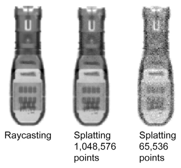
Methods for generating probe DRRs.
3.1. Direct splat correlation
On a CPU, splatting is normally more efficient than raycasting if the size of the point cloud is small compared to the size of the data volume it was derived from. However, the method translates poorly to the GPU because, for every point, an indirect write operation must be performed at a random pixel. However, we show here that the cross-correlation (CC) similarity metric can be rewritten so that these write operations can be replaced with extremely fast GPU texture reads.
Consider the CC between an XRF image I(u, v) and a DRR D(u, v) below:
| (6) |
We can substitute the D(u, v) term from Eq. (5) to obtain
| (7) |
This simplifies to a sum over all 3D points:
| (8) |
This expression simply states that the CC is equal to the sum, over all 3D points, of the point intensity times the intensity value of the image pixel that it projects onto. In this form, the CC metric does not require the DRR to be explicitly generated, enabling more efficient computation.
As this similarity is inspired by splatting and is directly computed from the image, it is referred to as “direct splat correlation” (DSC).
3.2. Patch gradient correlation
The DSC method was designed to perform similarity computations without the need for generating DRRs, potentially resulting in faster registration speeds. Metrics such as GCC and pattern intensity offer better registration accuracy; however, they are more computationally expensive (Penney et al., 1998).
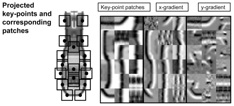
As an alternative to DSC, an algorithm was designed with a goal of achieving accuracy equal to or better than GCC combined with raycasting, while also achieving faster registration speeds. In XRF images, metallic devices tend to have a high degree of saliency compared to the anatomical background. This means that the device produces many high-contrast, high-entropy patches in the image that can be used as registration features. It was hypothesized that focusing on these salient features, rather than the entire image, would allow for accurate registration with a much lower computational burden. To that end, the new method computes the GCC metric on a subset of patches rather than the whole image, and is therefore called “patch gradient correlation” (PGC).
Prior to the registration procedure, a set of K 3D key-points on the TEE probe CT were manually defined once using 3D segmentation software (ITK-SNAP, Yushkevich et al. (2006)). The key-points were chosen based on their proximity to high contrast features on the probe (Fig. 3). During similarity computation, the key-points are projected on the image at each optimization iteration. At all K projected key-points, 16 × 16 DRR patches (D1…DK) are generated by raycasting. Patches are also extracted from the XRF image at the same locations (I1…IK). The similarity metric is the sum of the gradient correlation (see Eq. (3)) over all patches:
| (9) |
Fig. 3.
The PGC method. Left: an example of probe key-points projected onto an image of the probe, as well as the spatial footprint of the corresponding patches. Right: patches extracted from the locations of the projected key-points, with x and y gradients.
The location of key-points and patch extraction process are illustrated in Fig. 3. Notice that the overall footprint of the patches is small compared to the whole image, or even a sub-region surrounding the TEE probe. This dramatically reduces the number of rays that need to be cast, accelerating the registration process.
3.3. Hybrid method
In the previous sections, two novel 2D/3D registration algorithms were presented: DSC and PGC. It was hypothesized that the DSC method would be faster, while the PGC method would be more accurate. With this in mind, a hybrid (HYB) method was designed that utilized both methods. In the hybrid method, DSC was first used to arrive at an initial solution, while PGC was used to refine the solution. The idea was that this strategy would decrease the total number of iterations needed for the PGC method to converge by using the DSC method to provide a fast and accurate initialization. It was hypothesized that the hybrid method could achieve the same accuracy as PGC, but with a faster registration and higher capture range.
4. Experiments
Experiments were conducted to compare DSC, PGC, and HYB with previously reported XRF/TEE registration methods. Each method was evaluated in simulated and clinical datasets for accuracy, speed, and capture range.
4.1. Implementation
4.1.1. Prior methods
In order to compare the DSC, PGC and HYB algorithms with prior methods, it was necessary to implement the standard 2D/3D registration algorithm from Gao et al. (2012). This required a CUDA implementation of raycasting for DRR generation. The volumetric image (CTprobe(x, y, z)) used for generating DRRs was a 432 × 150 × 146 CBCT image of the TEE probe with 0.1037 mm × 0.1037 mm × 0.1037 mm voxel resolution acquired with a Philips FD20 system. Raycasting was implemented with a technique for improved computational efficiency that was not previously described in the literature, which increased registration speeds by a factor of 2–5 x (depending on imaging parameters). This technique calculated a DRR region-of-interest by only casting rays to the image pixels contained within a rectangular region bounding the projected corners of the CT volume (Fig. 4).
Fig. 4.
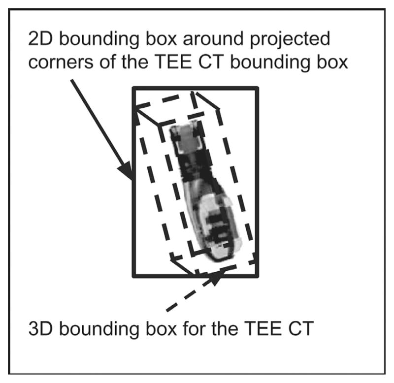
Illustration of the probe CT image used to generate the DRRs via raycasting, as well as the bounding box scheme for acceleration of the procedure.
The NCC (Eq. (1)) and GCC (Eq. (3)) metrics were used for similarity computations. Each was implemented in CUDA using the parallel reduction method presented in Harris et al. (2007) for mean and standard deviation calculation and finite differences for gradient calculation. To indicate that these “standard” registration methods combined raycasting with the NCC and GCC metrics, they are termed “rcNCC” and “rcGCC”.
4.1.2. DSC and PGC
The point cloud representation of the probe required for the DSC algorithm was created by: 1) Manually segmenting high-intensity regions in the TEE probe CT, 2) randomly generating points within the segmented region and, 3) assigning an intensity value to each point using linear interpolation of the CT scan.
The DSC algorithm was then implemented in CUDA, where high-performance was obtained by utilizing texture reads from the XRF image when computing the I(P · xrfTprobe · xj) term in Eq. (8).
PGC was implemented in CUDA using Eq. (4) for raycasting. Key-points were manually chosen based on visual assessment of saliency (high intensity blobs, edges and ridges).
4.2. Optimization strategy
All experiments assumed a single x-ray projection, which typically results in inaccurate estimates of tz. Therefore, we focused on optimization of the other five parameters, which resulted in a smaller optimization problem. Optimization consisted of two stages, first dealing with in-plane parameters (tx, ty, θz), and then the remaining parameters (tx, ty, θx, θy, θz). For the hybrid method, an initial solution was found using DSC with the same strategy, and then PGC was applied directly to all five parameters.
4.3. Computer hardware and software
A Philips X7-2t TEE probe was used in this study. All experiments were run on a Dell Precision T7500 work station running Ubuntu Linux with a 3.47 GHz Intel Xeon processor and a NVIDIA Tesla K20 GPU. VNL libraries were used for optimization. Retrospective clinical dataset processing was approved by the local institutional review board.
All source code for the various registration methods and simulation experiments presented in this paper can be downloaded using git at the following repository: https://github.com/chatti/hatt_media_2016.git.
4.4. Simulations
The simulation experiments tested the accuracy and speed of the DSC, PGC, rcNCC, rcGCC, and HYB methods in silico. Simulation images (Isim) were a hybrid of real background anatomy (Ixrf) and synthetic DRRs (Idrr).
A DRR of the probe was rendered using the splatting method with a point cloud large enough to generate a high quality DRR (221 points). The background anatomy was obtained using images from TAVR procedures and the hybrid image was formulated as
| (10) |
The parameter α controlled the probe to background contrast, and for each experiment was randomly varied to generate a contrast ratio ranging from 0.45 to 0.85. Examples of the simulated images are shown in Fig. 5.
Fig. 5.
Examples of simulated images.
For each experiment, the model of the TEE probe was placed at a random location and orientation in the virtual XRF C-arm space. Based on observations from a large set of images from TAVR cases, we noticed that the TEE probe usually had rotations about its long axis in the range of −75° to 75°, −30° to 30° about the x-axis of the image detector, and −45° to 45° about the axis perpendicular to the image. Therefore, the initial pose was randomly generated from a uniform distribution within those ranges. After determining the initial pose, a random mis-registration was applied, which the experiments attempted to recover. The mis-registration was chosen from a zero mean normal distribution with standard deviations of 1.5 mm, 1.5 mm, 2.5 mm, 10°, 10°, 5° for the parameters tx, ty, tz, θx, θy, θz, respectively. These values were chosen because they represented common inter-frame changes in pose as well as typical initial mis-alignments reported for automatic probe detection methods (Mountney et al., 2012; Hatt et al., 2015b).
In this study, the accuracy metric used was projection target registration error (pTRE), which was the root-mean-square error between known target points in XRF and estimated target points from echo following registration and projection to the XRF image:
| (11) |
where mn is the projective magnification of transformed fiducial point , and NFID = 25 are the number of fiducials.
pTRE and frame rate were reported for each experiment. For all experiments, virtual target points were used to compute pTRE. The virtual target points were randomly generated from within the center of a virtual ultrasound volume emanating from the TEE probe, at a mean distance of 50 mm from the probe face. The ground truth location of the virtual fiducials was found by transforming their location by , which was known for each simulation, and projecting their locations onto the image (Fig. 6, red circles). Errors due to probe model to echo volume calibration (probeTecho) were not considered in the analysis.
Fig. 6.
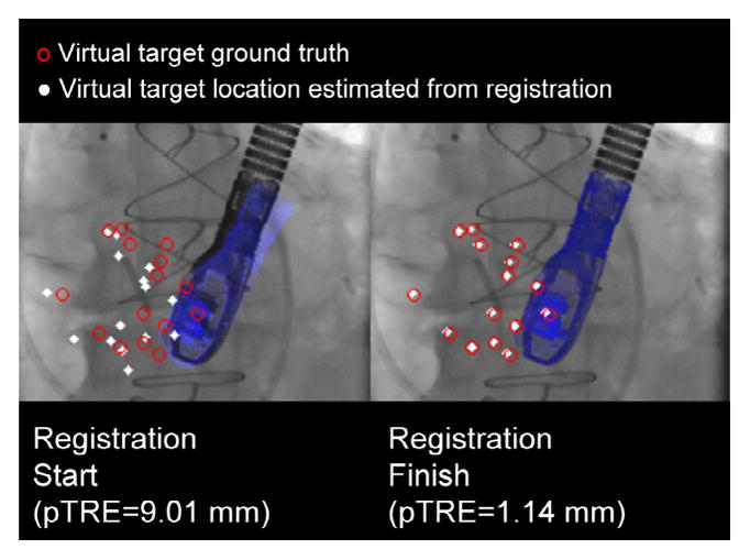
Virtual targets used to compute pTRE for the simulation experiments. (For interpretation of the references to colour in this figure legend, the reader is referred to the web version of this article.)
All algorithms (DSC, PGC, rcNCC, rcGCC, HYB) were tested with the Nelder–Mead and Powell optimizers. A point cloud size of 216 was used for the DSC method. 5000 simulated experiments were performed.
4.5. Clinical datasets
Validation was also performed on 91 image sequences from 81 TAVR cases (7994 frames). Due to a lack of ground truth, a proxy ground truth was needed. As the current state-of-the-art, we assumed that rcGCC was the best alternative in the absence of a real ground truth, and the following procedure was used to process all 7994 image frames:
Manual registration was performed for the first frame of each sequence.
The initial manual registration was refined using the rcGCC method.
The proxy ground truth registration was then found using rcGCC at each consecutive frame, using the registration result from the previous frame for initialization.
rcGCC could not successfully track the probe in two sequences, and they were removed from the analysis.
In the clinical datasets, tracking accuracy and robustness were tested under simulated clinical conditions where both image streaming and registration delays must be considered. Registration lag was calculated as nlag = ceil(15 × tregistration) frames (assuming 15 fps image streaming), resulting in frames being skipped if the registration time was larger than the frame interval (0.067 s). The pTRE for each skipped frame was calculated using the most recently finished registration result, and every registration (Tn) was initialized with the most recently processed registration (Tn−nlag). This meant that slower registrations resulted in increased pTRE due to not only more skipped frames but also less accurate frame-to-frame initializations.
5. Results
5.1. Simulations
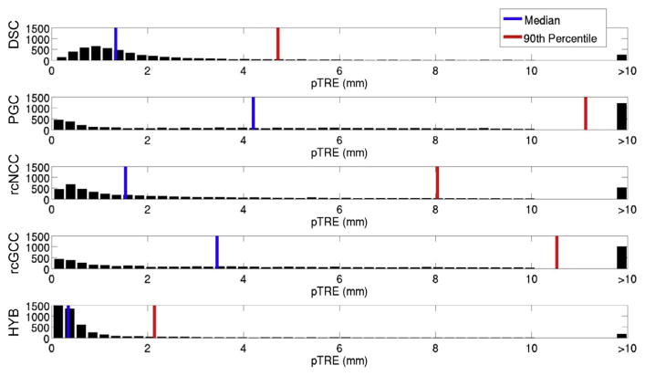
Registration timing results are shown in Fig. 7, while pTRE histograms are shown in Fig. 8. It can be seen that the DSC method is an order of magnitude faster than the rcGCC and rcNCC methods, averaging 30 ± 10 hz. The PGC and HYB methods are faster as well, both averaging faster than 10 hz. It is also important to note that the registration speeds obtained for the rcNCC and rcGCC method were faster than reported in Gao et al. (2012) and Housden et al. (2012), indicating that the differences in registration speeds were not artificially inflated.
Fig. 7.
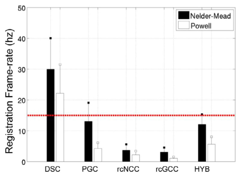
Frame-rate for each method in simulated datasets (mean + std).
Fig. 8.
pTRE histograms for the simulated datasets.
DSC and HYB clearly outperformed the other methods in terms of success rate, which is a proxy measure for capture range. PGC appeared to have the smallest capture range. For the PGC, rcNCC, rcGCC, and HYB methods, the error modes were all less than 0.5 mm, while for the DSC method, the error mode was slightly less than 1 mm. However, the DSC method failed less than the other methods.
The HYB method outperformed all methods in terms of success rate and registration accuracy, and was faster than rcNCC and rcGCC. While the DSC method greatly outperformed even the HYB method in terms of registration speed, the HYB method was almost fast enough to operate at fluoroscopic frame rates. All methods resulted in mean registration errors lower than the results reported in Housden et al. (2012) for clinical validation. However, errors resulting from echo to probe calibration were not considered in this study.
5.2. Clinical datasets
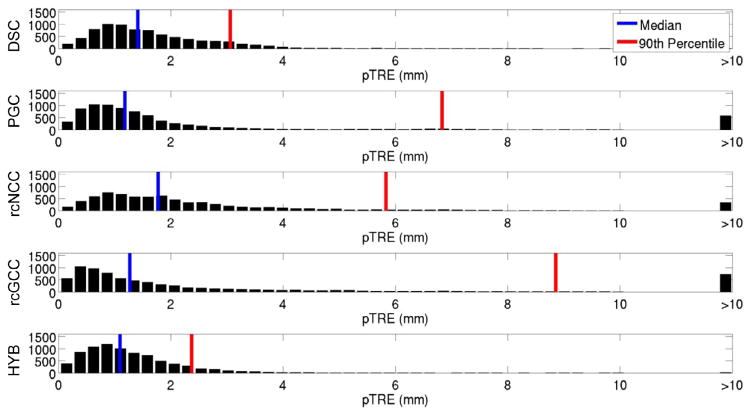
Results from the clinical datasets are summarized in Figs. 9 and 10. DSC and HYB outperformed all other methods in terms of registration accuracy, with HYB having the lowest errors. Registration speeds for each method roughly doubled, which is due to the fact that most frame-to-frame differences in registration were small in the clinical datasets and therefore fewer iterations were needed on average.
Fig. 9.
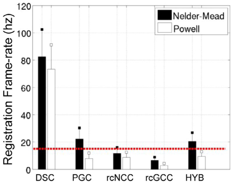
Frame-rates for clinical datasets (mean ± std).
Fig. 10.
pTRE histogram for the clinical datasets.
In the simulation experiments, which did not consider x-ray video and image streaming lags, the DSC method was the least accurate and the HYB method showed comparable accuracy to rcGCC. In the clinical experiments the image streaming rate was fixed and an algorithm was forced to drop frames if it could not keep pace. The fact that the HYB method had the lowest median pTRE and that the HYB and DSC methods both had the lowest 90th percentile pTREs in this more realistic scenario indicates that target registration error is worse in slower algorithms which initialize each new frame with relatively old pose estimates. This highlights the need for real-time algorithms in the presence of motion.
6. Discussion
In this work, the DSC, PGC and HYB methods for pose-estimation of devices were presented and validated against the standard rcNCC and rcGCC methods in a XRF/TEE image registration scenario. The main conclusions from these experiments were that the DSC method was much faster than all of the other methods, and DSC was capable of achieving registration frame rates that greatly exceeded clinical requirements. The DSC method was also more robust than the rcNCC and rcGCC methods, as indicated by the lower median and 90th percentile errors. The PGC method was similar in terms of the accuracy to rcGCC, but slightly less robust. Results indicated that the HYB method was able to successfully combine the speed and high capture range of DSC with the accuracy of PGC, resulting in robust and accurate 5DOF registration at or near fluoroscopic frame rates.
Of note are the lack of tracking failures from the DSC and HYB methods in the clinical datasets. This points to the importance of high frame-rate tracking that not only minimizes registration errors caused by probe movement during skipped frames, but also minimizes tracking failures due to sudden movements of the probe outside of the capture range of the algorithm.
Aside from the problem of tracking the pose of the TEE probe, the DSC and HYB algorithms may also be applicable to other 2D/3D registration problems. For example, lung tumor tracking by 2D/3D registration for radiotherapy was proposed in Gendrin et al. (2012), where the authors showed an update rate of 2 hz. Using the DSC or HYB methods presented here could result in improved therapeutic targeting accuracy by improving the update speed. Recently, Ralovich et al. (2014) reported on an intracardiac echo (ICE) catheter with embedded fiducial markers for 6DOF XRF/ICE, and the methods presented in this work may be suitable for that application.
7. Conclusion
This work presents two novel 2D/3D registration algorithms: Direct Splat Correlation (DSC) and Patch Gradient Correlation (PCG). They were both validated in a x-ray/echo registration scenario, along with a hybrid method that combined them. DSC was extremely fast (~80 hz in clinical datasets) and resulted in fewer tracking failures than prior state-of-the-art methods, but it was also slightly less accurate. PGC was also faster than prior methods, but it had similar accuracy. Finally, the hybrid method resulted in x-ray/echo registration that achieved real-time registration speeds, as well as the greatest accuracy.
Acknowledgments
Partial financial support for this work was provided by NIH Grant No. R01 HL084022 and Philips Research North America.
References
- Birkfellner W, Seemann R, Figl M, Hummel J, Ede C, Homolka P, Yang X, Niederer P, Bergmann H. Wobbled splattinga fast perspective volume rendering method for simulation of X-ray images from CT. Phys Med Biol. 2005;50(9):N73. doi: 10.1088/0031-9155/50/9/N01. [DOI] [PubMed] [Google Scholar]
- Gao G, Penney G, Gogin N, Cathier P, Arujuna A, Wright M, Caulfield D, Rinaldi A, Razavi R, Rhode K. Information Processing in Computer-Assisted Interventions. Springer; Geneva, Switzerland: 2010. Rapid image registration of three-dimensional transesophageal echocardiography and X-ray fluoroscopy for the guidance of cardiac interventions; pp. 124–134. [Google Scholar]
- Gao G, Penney G, Ma Y, Gogin N, Cathier P, Arujuna A, Morton G, Caulfield D, Gill J, Rinaldi CA, et al. Registration of 3D trans-esophageal echocardiography to X-ray fluoroscopy using image-based probe tracking. Med Image Anal. 2012;16(1):38–49. doi: 10.1016/j.media.2011.05.003. [DOI] [PubMed] [Google Scholar]
- Gendrin C, Furtado H, Weber C, Bloch C, Figl M, Pawiro SA, Bergmann H, Stock M, Fichtinger G, Georg D, et al. Monitoring tumor motion by real time 2D/3D registration during radiotherapy. Radiother Oncol. 2012;102(2):274–280. doi: 10.1016/j.radonc.2011.07.031. [DOI] [PMC free article] [PubMed] [Google Scholar]
- Harris M, et al. Optimizing parallel reduction in cuda. NVIDIA Developer Technol. 2007;2(4) [Google Scholar]
- Hatt C, Speidel M, Raval A. Hough forests for real-time, automatic device localization in fluoroscopic images: application to TAVR. In: Navab N, Hornegger J, Wells WM, Frangi AF, editors. Medical Image Computing and Computer-Assisted Intervention – MICCAI 2015. Lecture Notes in Computer Science. Vol. 9349. Springer International Publishing; Munich, Germany: 2015a. pp. 307–314. [DOI] [Google Scholar]
- Hatt CR, Speidel MA, Raval AN. Medical Image Computing and Computer-Assisted Intervention–MICCAI 2015. Springer; Munich, Germany: 2015b. Hough forests for real-time, automatic device localization in fluoroscopic images: application to TAVR; pp. 307–314. [Google Scholar]
- Hatt CR, Speidel MA, Raval AN. Medical Image Computing and Computer-Assisted Intervention–MICCAI 2015. Springer; Munich, Germany: 2015c. Robust 5DOF transesophageal echo probe tracking at fluoroscopic frame rates; pp. 290–297. [Google Scholar]
- Heimann T, Mountney P, John M, Ionasec R. Real-time ultrasound transducer localization in fluoroscopy images by transfer learning from synthetic training data. Med Image Anal. 2014;18(8):1320–1328. doi: 10.1016/j.media.2014.04.007. [DOI] [PubMed] [Google Scholar]
- Housden RJ, Arujuna A, Ma Y, Nijhof N, Gijsbers G, Bullens R, ONeill M, Cooklin M, Rinaldi CA, Gill J, et al. Medical Image Computing and Computer-Assisted Intervention–MICCAI 2012. Springer; Nice, France: 2012. Evaluation of a real-time hybrid three-dimensional echo and X-ray imaging system for guidance of cardiac catheterisation procedures; pp. 25–32. [DOI] [PubMed] [Google Scholar]
- Jain A, Gutierrez L, Stanton D. Functional Imaging and Modeling of the Heart. Springer; Nice, France: 2009. 3D TEE registration with X-ray fluoroscopy for interventional cardiac applications; pp. 321–329. [Google Scholar]
- Kronzon I, Jelnin V, Ruiz CE, Saric M, Williams MR, Kasel AM, Shivaraju A, Colombo A, Kastrati A. Optimal imaging for guiding TAVR: Transesophageal or transthoracic echocardiography, or just fluoroscopy? JACC: Cardiovasc Imaging. 2015;8(3):361–370. doi: 10.1016/j.jcmg.2015.01.003. [DOI] [PubMed] [Google Scholar]
- Lang P, Seslija P, Chu MW, Bainbridge D, Guiraudon GM, Jones DL, Peters TM. US–fluoroscopy registration for transcatheter aortic valve implantation. Biomed Eng IEEE Trans. 2012;59(5):1444–1453. doi: 10.1109/TBME.2012.2189392. [DOI] [PubMed] [Google Scholar]
- Markelj P, Tomaževič D, Likar B, Pernuš F. A review of 3D/2D registration methods for image-guided interventions. Med Image Anal. 2012;16(3):642–661. doi: 10.1016/j.media.2010.03.005. [DOI] [PubMed] [Google Scholar]
- Mountney P, Ionasec R, Kaizer M, Mamaghani S, Wu W, Chen T, John M, Boese J, Comaniciu D. Medical Image Computing and Computer-Assisted Intervention–MICCAI 2012. Springer; Nice, France: 2012. Ultrasound and fluoroscopic images fusion by autonomous ultrasound probe detection; pp. 544–551. [DOI] [PubMed] [Google Scholar]
- Penney GP, Weese J, Little JA, Desmedt P, Hill DL, Hawkes DJ. A comparison of similarity measures for use in 2D/3D medical image registration. Med Imaging IEEE Trans. 1998;17(4):586–595. doi: 10.1109/42.730403. [DOI] [PubMed] [Google Scholar]
- Ralovich K, John M, Camus E, Navab N, Heimann T. 6DOF catheter detection, application to intracardiac echocardiography. In: Golland P, Hata N, Barillot C, Hornegger J, Howe R, editors. Medical Image Computing and Computer-Assisted Intervention MICCAI 2014. In: Lecture Notes in Computer Science. Vol. 8674. Springer International Publishing; Boston, US: 2014. pp. 635–642. [DOI] [PubMed] [Google Scholar]
- Yushkevich PA, Piven J, Cody Hazlett H, Gimpel Smith R, Ho S, Gee JC, Gerig G. User-guided 3D active contour segmentation of anatomical structures: Significantly improved efficiency and reliability. Neuroimage. 2006;31(3):1116–1128. doi: 10.1016/j.neuroimage.2006.01.015. [DOI] [PubMed] [Google Scholar]


