Abstract.
The purpose of this work was to develop a clinically viable laparoscopic augmented reality (AR) system employing stereoscopic (3-D) vision, laparoscopic ultrasound (LUS), and electromagnetic (EM) tracking to achieve image registration. We investigated clinically feasible solutions to mount the EM sensors on the 3-D laparoscope and the LUS probe. This led to a solution of integrating an externally attached EM sensor near the imaging tip of the LUS probe, only slightly increasing the overall diameter of the probe. Likewise, a solution for mounting an EM sensor on the handle of the 3-D laparoscope was proposed. The spatial image-to-video registration accuracy of the AR system was measured to be and for the left- and right-eye channels, respectively. The AR system contributed 58-ms latency to stereoscopic visualization. We further performed an animal experiment to demonstrate the use of the system as a visualization approach for laparoscopic procedures. In conclusion, we have developed an integrated, compact, and EM tracking-based stereoscopic AR visualization system, which has the potential for clinical use. The system has been demonstrated to achieve clinically acceptable accuracy and latency. This work is a critical step toward clinical translation of AR visualization for laparoscopic procedures.
Keywords: augmented reality, camera calibration, electromagnetic tracking, stereoscopic laparoscopy, ultrasound calibration
1. Introduction
Minimally invasive laparoscopic surgery is an attractive alternative to conventional open surgery and is known to improve outcomes, cause less scarring, and lead to significantly faster patient recovery.1 For certain surgical procedures, such as cholecystectomy (removal of the gall bladder), it has become the standard of care.2 In laparoscopic procedures, real-time video of the surgical field acquired by a laparoscopic camera is the primary means of intraoperative visualization and navigation. The laparoscope and other surgical tools are inserted into the patient’s body through trocars, mounted typically at three-to-four locations on the abdomen. Compared with open surgery, conventional laparoscopy lacks tactile feedback. Furthermore, it provides only a surface view of the organs and cannot show anatomical structures and surgical targets located beneath the exposed organ surfaces. These limitations create a greater need for enhanced intraoperative visualization during laparoscopic procedures to achieve safe and effective surgical outcomes.
Laparoscopic augmented reality (AR), a method to overlay tomographic images on live laparoscopic video, has emerged as a promising technology to enhance intraoperative visualization. Many recent works on laparoscopic AR visualization registered and fused intraoperative imaging data with live laparoscopic video.3–9 Intraoperative imaging has the advantage of providing real-time updates of the surgical field and, thus, enables AR depiction of moving and deformable organs, such as those located in the abdomen, the thorax, and the pelvis. Computed tomography (CT) and laparoscopic ultrasound (LUS) are the two major intraoperative imaging modalities used for such augmentation. Compared with CT, LUS is more amenable to routine use because it is radiation-free, low-cost, and easy to setup and handle in the operating room (OR). For these reasons, LUS is the modality of choice in our AR research, including this study.
Although a 2-D laparoscope is the standard instrument currently used in the OR, laparoscopes offering stereoscopic (3-D) visualization have been introduced and are being gradually adopted. Stereoscopic visualization provides surgeons better perception of depth and improved understanding of 3-D spatial relationships among visible anatomical structures. Its use in laparoscopic tasks has been reported to be efficient and effective.10,11 As reported by our team and a few others,7,9 it can also be used in AR visualization.
To ensure accurate image fusion, a registration method is needed before overlaying tomographic images on laparoscopic video. This registration can be achieved through different approaches. A promising but still evolving approach is the vision-based approach,3,5,6,12,13 which uses computer vision techniques to track in real-time intrinsic landmarks and/or user-introduced patterns within the field of view. Although no external tracking hardware is needed, the vision-based approach needs further research and development to achieve the accuracy and robustness needed for reliable clinical use. In current practice, the use of external tracking hardware is necessary. The most established real-time tracking method at present is optical tracking, which uses an infrared camera to track optical markers affixed rigidly to the desired tools. The method has been used in many AR applications;4,8,9 however, an AR system based on optical tracking can be restrictive because of the line-of-sight requirement. For example, the use of optical tracking in LUS-based AR systems requires the optical markers to be placed on the handle of the LUS probe, maintain a rigid geometric relationship with the LUS transducer, and be visible to the infrared camera at all times. These requirements do not permit the use of a key feature of the flexible LUS probe, i.e., the four-way articulation (bending) of the imaging tip that is critical to scanning areas that are difficult to reach by a rigid probe. This and other lessons learned from our clinical translation efforts, i.e., an Institutional Review Board (IRB)-approved clinical evaluation study involving an optical tracking-based AR system,14 have motivated us to explore a tracking solution independent of the line-of-sight requirement.
A logical alternative is to use electromagnetic (EM) tracking, another commercially available real-time tracking method. EM tracking reports the location and orientation of a small ( diameter) wired sensor inside a 3-D working volume with a magnetic field created by a field generator. Many groups have studied the accuracy of EM tracking in real or simulated clinical settings,15–18 as well as configurations in which an EM sensor is embedded in imaging probes.19 One limitation of EM tracking is the potential distortion of the magnetic field due to ferrous metals and conductive materials inside the working volume. Because both the LUS probe and the laparoscope contain such materials, the precise location where EM sensors are attached to the two imaging devices is a critical consideration. Although Cheung et al.7 reported an AR system based on EM tracking, the investigators do not describe where the sensors were placed on the two imaging probes, what the EM tracking errors associated with these locations were, or whether or not these locations were clinically practical. Feuerstein et al.20 proposed a hybrid optical-EM method to track the flexible tip of the LUS probe. However, the study focused on tracking the LUS probe only and not the laparoscope, and the attachment of the sensor appears to be a laboratory solution (i.e., cannot be implemented clinically).
Development of a clinically viable system and pursuit of clinical translation in the near-term motivates our research. In this work, we have developed a fully integrated and compact stereoscopic AR visualization system based on EM tracking (called EM-AR henceforth). Specifically, we investigated clinically feasible solutions to mount the EM sensors on the 3-D laparoscope and the LUS probe. To improve portability of the system, we implemented the image fusion software on a graphics processing unit (GPU)-accelerated laptop. In addition, we developed a vascular ultrasound phantom, which simulates blood flow in a blood vessel. We used the phantom to both demonstrate and evaluate AR overlay accuracy based on the color Doppler imaging. In addition to these technical contributions, another focus of our work lies in rigorous quantitative and qualitative validation of the performance of the EM-AR system in terms of spatial registration accuracy and system latency. We further performed an animal experiment to demonstrate the safety and performance of using the EM-AR system as a visualization approach for laparoscopic procedures, in a model physiologically similar to humans. Laparoscopic AR system has been studied by many groups for years; however, there is still not a single system that can be used clinically. The proposed system is significant in that it bridges the gap between a laboratory prototype and a clinical-grade system.
2. Materials and Methods
2.1. System Overview
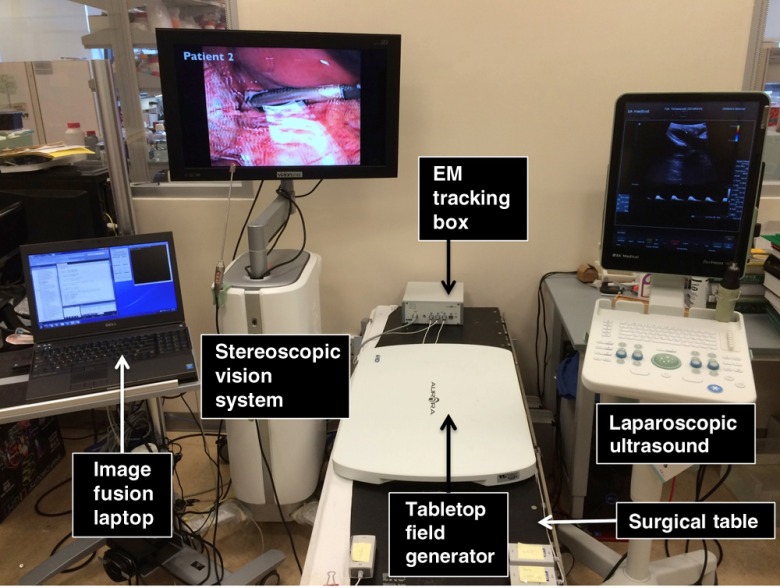
As shown in Fig. 1, the EM-AR system includes a stereoscopic vision system (VSII, Visionsense Corp., New York), an LUS scanner (Flex Focus® 700, BK Medical, Herlev, Denmark), an EM tracking system with a tabletop field generator (Aurora®, Northern Digital Inc., Waterloo, Ontario, Canada), and a laptop computer running image fusion software. The stereoscopic vision system comes with a 30-cm long 5-mm (outer diameter) 0-deg laparoscope (referred to as the 3-D scope). Unlike a conventional 2-D laparoscope that can be disassembled into a camera head, a telescope shaft, and a light source, the Visionsense 3-D scope has a unique one-piece design with integrated camera and light source, fixed focal length, and automated white balance. The 3-D scope has been reported to subjectively improve depth perception and achieve excellent clinical outcomes.21 The LUS scanner, capable of gray-scale B-mode and color Doppler mode, employs an intraoperative 9-mm laparoscopic transducer. The tabletop EM field generator is specially designed for OR applications. It is positioned between the surgical table and the patient and incorporates a shield that suppresses most distortions caused by metallic materials underneath it. A recent study showed that the tabletop arrangement could reduce EM tracking error in the clinical environment compared to the well-established standard Aurora® Planar field generator.16 In this study, we used EM catheter tools (Aurora® Catheter Type 2), each containing a 6-degrees of freedom (DOF) sensor at the tip. The catheter is thin (1.3-mm diameter) and can stand cycles of autoclave sterilization.
Fig. 1.
The EM-AR system.
Let denote a point in the LUS image in homogeneous coordinates, in which the coordinate is 0. Let denote the point that corresponds to in the undistorted laparoscopic video image. If we denote as the transformation matrix from the coordinate system of A to that of B, the relationship between and can be expressed as
| (1) |
where US refers to the LUS image; refers to the sensor attached to the LUS probe; EMT refers to the EM tracking system; refers to the sensor attached to the 3-D scope; lens refers to the camera lens of the 3-D scope; is a unit matrix of size 3; and is the camera matrix. can be obtained from ultrasound calibration; and can be obtained from tracking data; can be obtained from hand-eye calibration; and can be obtained from camera calibration. can be distorted using lens distortion coefficients also obtained from camera calibration.
2.2. Electromagnetic Sensor Location
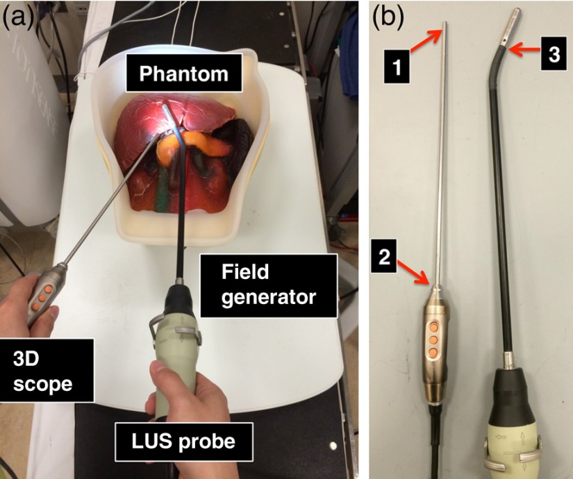
Figure 2(a) shows a typical arrangement of how the two imaging probes are likely to be positioned above the EM-field generator during a laparoscopic procedure. The LUS probe is inserted into the patient through a 10- or 12-mm trocar, which is usually positioned at the umbilicus (belly button) of the patient. The 3-D scope is generally inserted through a 5-mm trocar, positioned on either side of the abdomen (left or right upper quadrant). For the 3-D scope, one could place the sensor close to the tip of the scope [position 1 in Fig. 2(b)]. Although this may improve calibration accuracy, the solution would inevitably increase the trocar size needed for introducing the scope because a mechanical sleeve (or some other types of tracking mounts) needs to be designed and integrated with the scope to secure the sensor catheter along the scope shaft. Moreover, leaving the tracking instrument inside the patient body throughout most of the surgery will require additional safety and risk studies. A more practical solution is to mount the EM sensor on the handle of the 3-D scope [position 2 in Fig. 2(b)] such that the sensor holder is kept outside patient’s body during the surgery. Because there are more metal and electronics contained in the handle of the 3-D scope than in the scope shaft, there is the potential for larger distortion error in the EM tracker readings in the vicinity of the handle. To reduce this error, it is necessary to place the sensor sufficiently far away from the handle.
Fig. 2.
(a) A typical arrangement of the two imaging probes during a laparoscopic procedure. (b) Possible locations to place the EM sensor on the two imaging probes.
We measured positional and rotational distortion and jitter errors of EM tracking when the sensor was placed at several locations near the scope handle. Let and be the positional and rotational mean values when the sensor was near the handle of the 3-D scope, respectively, and and be those values when the scope was removed from the scene while the sensor was kept untouched. We quantified the positional distortion error to be , where denotes the Euclidian distance, and the rotational distortion error to be the angle difference of and , calculated as22
| (2) |
where and denote the direct cosine matrices associated with and , respectively. Jitter error measures the random noise when the sensor is not moving. We quantified positional and rotational jitter errors as the root-mean-square errors between the tracking data and their means, when the sensor was fixed near the scope handle. For calculating rotational errors, we estimated the mean of rotations using a singular value decomposition approach based on the quaternion form of rotations.22,23
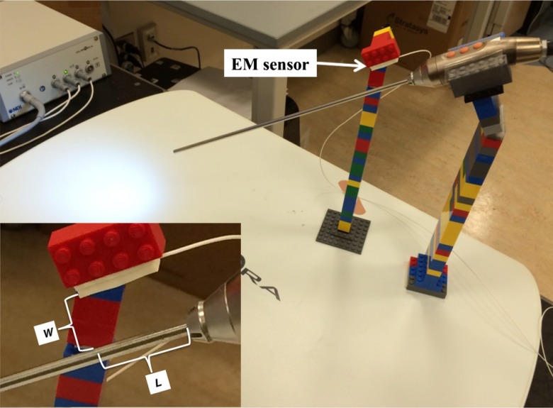
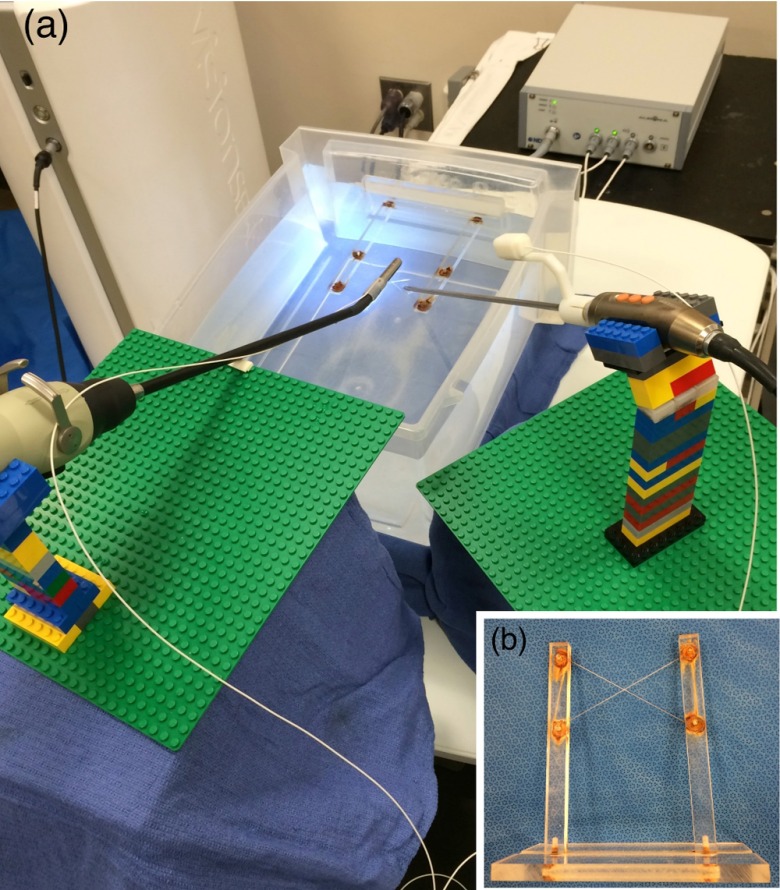
As shown in Fig. 3, we positioned the 3-D scope at several locations on the field generator at a 30-deg angle using LEGO® bricks. The bricks are suitable for use in conjunction with EM tracking systems because they are made of plastic and cause no distortion of the magnetic field. Their small size makes creating very precise designs possible, and any design created using them is reconfigurable and reproducible.15 The 30 deg is a typical angulation for the laparoscope during laparoscopic procedures. An EM sensor was attached to a brick using tape and positioned above the 3-D scope near the handle. As shown in the close-up view of Fig. 3, if the sensor is kept parallel to the axis of the 3-D scope, the location of the sensor relative to the handle is dependent on two variables: the radial distance from the sensor to the outer surface of the 3-D scope and the axial distance from the projection of the sensor tip on the 3-D scope to the distal edge of the handle.
Fig. 3.
Experimental setup to measure EM tracking errors when placing the sensor close to the handle of the 3-D scope. The close-up view shows the definitions of and .
According to our experiments, both distortion and jitter errors decrease as the value of increases, indicating that the farther the sensor is longitudinally from the handle, the smaller is the EM tracking error. However, there is no apparent trend for , so we placed the sensor at , which is about the largest to ensure that the associated tracking mount does not interfere with the patient during the surgery. We also selected , which is about the minimum value of to allow free rotation of the trocar. At this designated sensor location, the mean positional and rotational distortion errors were 0.31 mm and 0.25 deg, and the mean positional and rotational jitter errors were 0.10 mm and 0.18 deg.
To track the flexible tip of the LUS probe, it is necessary to affix the EM sensor near the movable imaging tip [position 3 in Fig. 2(b)] such that the rigid relationship between the sensor and the imaging tip is maintained. The sensor should also be kept as close to the skin (outer surface) of the LUS probe as possible to allow insertion through a trocar of either the same size or not much bigger than the one needed for the original transducer. We measured EM tracking errors in a similar way as for the 3-D scope by placing the sensor as close as possible (i.e., 1.5 mm away in the direction) to the skin of the imaging tip of the LUS probe, which was positioned at several locations on the field generator. The mean positional and rotational distortion errors were 0.13 mm and 0.95 deg, and the mean positional and rotational jitter errors were 0.02 mm and 0.03 deg.
Our experiments indicate that the distortion and jitter errors of EM tracking are sufficiently small at these designated sensor locations. One exception could be the rotational distortion error for the LUS probe; however, its effect on the overall system accuracy is limited due to the small distance from the sensor to the ultrasound image plane.
2.3. Electromagnetic Tracking Mounts
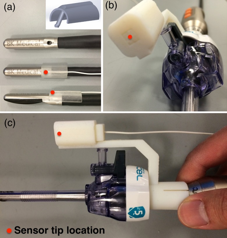
We designed and built mechanical tracking mounts that could be snugly and reproducibly snapped on to the two imaging probes, such that the EM sensors are positioned at known designated locations. These mounts were printed using a 3-D printer (Objet500 Connex, Stratasys Ltd., Eden Prairie, Minnesota) with materials that can withstand the commonly used low-temperature sterilization process (e.g., STERRAD®, ASP, Irvine, California). For the LUS transducer, a wedge-like mount was made to attach to an existing biopsy needle introducer track, as shown in Fig. 4(a). In our design, the distance between the EM sensor and the surface of the LUS shaft is 1 mm. The mount adds 3.6 mm to the original diameter (8.7 mm) of the LUS probe, but the integrated probe can still be introduced through a 12-mm trocar (the inner diameter of a 12-mm trocar is actually 12.8 mm). Figures 4(b) and 4(c) show the tracking mount for the 3-D scope, which was shown inserted into a 5-mm plastic trocar.
Fig. 4.
Snap-on mechanical tracking mounts. (a) Mount for the LUS probe. (b) and (c) Two views of the mount for the 3-D scope inserted through a 5-mm trocar.
2.4. Calibration
For creating AR, the ultrasound image must be rendered using a virtual camera that mimics the optics of an actual laparoscopic camera. This necessitates camera calibration, a well-studied procedure in computer vision. For calibrating intrinsic camera parameters and distortion coefficients, we used the automated camera calibration module in OpenCV library (Intel Corp., Santa Clara, California).24 A custom-designed calibration phantom with a checkerboard pattern of alternating 5-mm black and white squares in the central region was 3-D printed. This gives corner points in the pattern. The size of the square was chosen to ensure that the entire checkerboard stayed within the 3-D scope’s field of view at the working distance of 5 to 10 cm. For calibration, we acquired 40 images of the checkerboard pattern from various poses of the 3-D scope. Hand-eye calibration25 that relates the attached EM sensor coordinate system with the scope lens coordinate system, i.e., in Eq. (1), was performed using OpenCV’s solvePNP function with the coordinates of checkerboard corners in the EM sensor coordinate system as input. Hand-eye calibration results of the 40 images were averaged to yield the final transformation. The coordinates of corner points in the EM tracker coordinate system were obtained by touching three divots with a precalibrated and tracked stylus (Aurora 6DOF Probe, Straight Tip, NDI). The divots were also printed on the calibration phantom with a known geometric relationship to each corner point. The 3-D scope was treated as a combination of two standalone cameras (left- and right-eye channels), each of which was calibrated separately (see Sec. 4 for more details).
Ultrasound calibration determines the transformation between ultrasound image pixel coordinates and the EM sensor attached to the ultrasound transducer, i.e., in Eq. (1). We used the method available in the PLUS library,26 a freely available, open-source library that includes well-tested calibration software and instructions for building the associated calibration phantom. A modified PLUS phantom, integrated with an EM sensor and equipped with three “N” shapes (also called N-wires), was 3-D printed. The PLUS software was also modified to accommodate communication with the BK ultrasound scanner.
2.5. Video Processing
Combining the tracking data and calibration results, the LUS images were registered and overlaid on the stereoscopic video, forming two ultrasound-augmented video streams, one for the left eye and one for the right eye. The composite AR streams were then rendered for interlaced 3-D display. To reduce video processing time, functions involved in this image fusion module, such as texture mapping, alpha blending, and interlaced display, were performed using OpenGL (Silicon Graphics, Sunnyvale, California) on a GPU.
In our previous prototype,9 the image fusion module was implemented in a high-end desktop workstation (8-core 3.2-GHz Intel CPU, 12 GB memory) with a modern graphics card (Quadro 4000, NVidia, Santa Clara, California). In this work, we migrated the fusion module to a laptop computer (Precision M4800, Dell; 4-core 2.9 GHz Intel CPU, 8 GB memory), available with a mobile GPU (Quadro K2100M, NVidia). While mobile GPUs are often less powerful than their desktop counterparts, the Quadro K2100M is based on a newer NVIDIA architecture and contains more cores than the Quadro 4000 (576 cores versus 256 cores). The purpose of this migration was to improve portability so that the laptop could be placed on a small cart or integrated into the vision tower in the future.
To speed up data transfer, the stereoscopic video and LUS images were streamed to the image fusion module over gigabyte Ethernet from the two imaging devices. We adapted an OEM Ethernet communication protocol, provided by BK Medical, to communicate between the image fusion laptop and the LUS scanner. Stereoscopic video images were similarly streamed from the vision system using its Ethernet OEM interface.
3. Experiments and Results
3.1. Target Registration Error
To simulate a clinical setting, all validation experiments were performed on a real surgical table as shown in Fig. 1. The spatial registration of the EM-AR system is critically dependent on accurate camera and ultrasound calibrations. We tested device calibration independently before evaluating the registration accuracy of the overall system. For these tasks, we used target registration error (TRE), the difference between the ground-truth and the observed coordinates of a landmark (point in 3-D space), as the accuracy metric.
For the LUS calibration TRE, a target point was imaged using the LUS probe. Its estimated location in the EM tracker coordinate system was obtained using the calibration result, i.e., through transforms , and compared with the actual location of the target point. For the 3-D scope calibration TRE, images of the checkerboard pattern were acquired from two different viewpoints. The locations of pattern corners in the EM tracker coordinate system were estimated using the calibration result and triangulation of the two views (we used the iterative linear triangulation method in the referenced paper).27 These estimated locations were compared with the actual locations of the pattern corners.
As shown in Fig. 5(a), to measure the overall image-to-video TRE, a target point was imaged using the LUS probe, and its pixel location was identified in the LUS image overlaid on the video image. Aiming the 3-D scope at the target point from two different viewpoints, the coordinates of the target point in the EM tracker coordinate system were estimated using triangulation and compared with the actual location of the target point. For both the LUS calibration and the overall system TREs, the target point was the intersection of a cross-wire phantom,28 as shown in Fig. 5(b). The actual location of the intersection was acquired using a precalibrated and tracked stylus. For all TRE measurements, the experiment was performed at eight different locations within the working volume of EM tracking. At each position, the TRE was measured three times.
Fig. 5.
(a) Experimental setup to measure the overall image-to-video TRE. (b) Cross-wire phantom used to create a target point, i.e., the intersection of the two wires.
The TRE of the LUS transducer calibration was . The TREs of the 3-D scope calibration were and for the left- and right-eye cameras, respectively. The overall AR system image-to-video TREs were and for the left- and right-eye channels, respectively. These results are discussed in additional detail in Sec. 4.
3.2. Abdominal Ultrasound Phantom
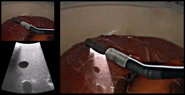
An abdominal ultrasound phantom (IOUSFAN, Kyoto Kagaku Co. Ltd., Kyoto, Japan), created specifically for laparoscopic applications, was used to demonstrate the visualization capability of the EM-AR system [the phantom is shown in Fig. 2(a)]. Two video clips showing the performance of our system have been supplied as multimedia files (Fig. 6).
Fig. 6.
Imaging an abdominal phantom using the EM-AR system. The video shows the left-eye channel of live stereoscopic EM-AR visualization with ultrasound calibrated at the depth of 6.4 cm. The videos also show the original views of the laparoscope and the ultrasound. (Video 1, MP4, 16.5 MB [URL: http://dx.doi.org/10.1117/1.JMI.3.4.045001.1]; Video 2, MP4, 10.5 MB [URL: http://dx.doi.org/10.1117/1.JMI.3.4.045001.2].)
3.3. Vascular Ultrasound Phantom
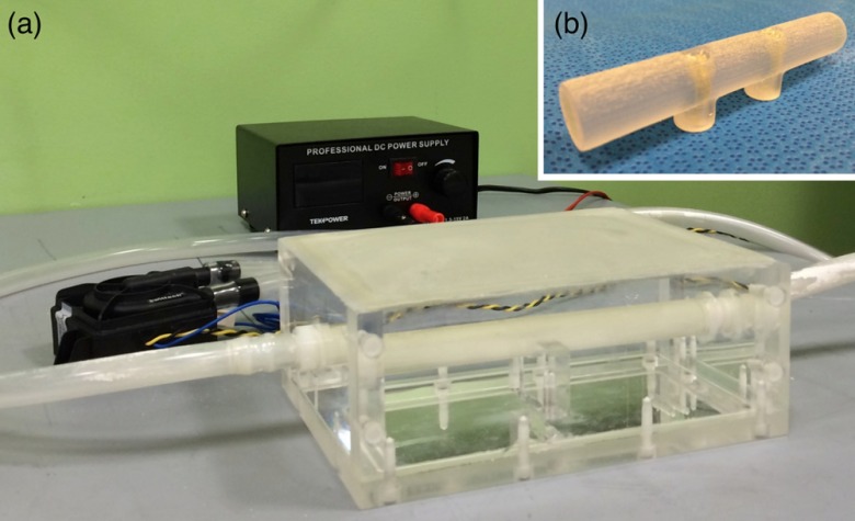
As shown in Fig. 7(a), we created a purpose-built vascular ultrasound phantom as another demonstration of accurate AR visualization. The phantom has a hollow box to be filled with water during an experiment. A hollow plastic circular tube was fixed inside the box. The plastic tube was connected to two outside rubber tubes, one on each end, and the outside rubber tubes were connected to an electric water pump. The plastic tube inside the box simulates a blood vessel, and is visible in B-mode ultrasound. When water is circulated through the tube, the tube can also be visualized with Doppler ultrasound. A stereoscopic AR depiction of this tube is, therefore, possible using the EM-AR system.
Fig. 7.
(a) The vascular ultrasound phantom. (b) A simple tube phantom.
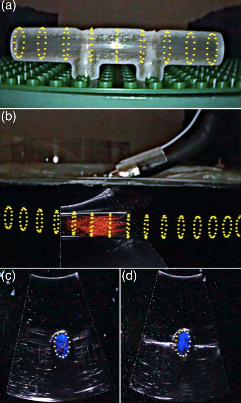
The original goal was to compare the tube shown in the ultrasound image, overlaid on the laparoscopic video image, with the tube inside the box shown in the laparoscopic video image. However, due to refraction of light in glass and water, the tube inside the box seen in the laparoscopic video may not represent the true location of the tube. Therefore, we created a virtual representation of the tube and superimposed it on the video image as the reference. A mathematical model of a series of rings in 3-D space was developed to represent a 3-D tube and then registered with the tube inside the box. The registered virtual tube was then transformed to the video image using the laparoscope calibration result and, finally, rendered for display.
Because of this indirect comparison, we first need to validate the accuracy of the virtual tube model. To achieve this, we created a separate simple tube phantom [Fig. 7(b)] with the same diameter as the tube inside the box and registered the virtual tube with this simple tube phantom. Because these is no refraction issue associated with this simple tube phantom, good spatial agreement between the virtual tube and the simple tube phantom shown in the video image, as demonstrated in Fig. 8(a), indicates accurate virtual tube registration, i.e., good laparoscope calibration.
Fig. 8.
Virtual representation of the tube (yellow) overlaid on the simple tube phantom. (b) A view of overlaying color Doppler ultrasound image with the virtual tube model. (c) and (d) Two cross-section views of the overlay. Pictures were acquired from the right-eye channel of live stereoscopic AR visualization.
We dyed the water in the vascular phantom box black for a realistic laparoscope camera view (i.e., cannot see internal structures). Figure 8(b) shows an AR scene of overlaying color Doppler LUS image with the virtual tube model. To achieve good Doppler signal, it is necessary to steer the imaging tip and maintain an angle () between the ultrasound beam and the water flow. As can be seen, both the color Doppler signal showing the flow and the B-mode signal showing the outline of the tube align well with the virtual model of the tube. Figures 8(c) and 8(d) show two cross-sectional views of the overlaid Doppler ultrasound image with the virtual tube model. In these figures, only one circle representing the cross-section of the tube was rendered for clarity.
3.4. System Latency
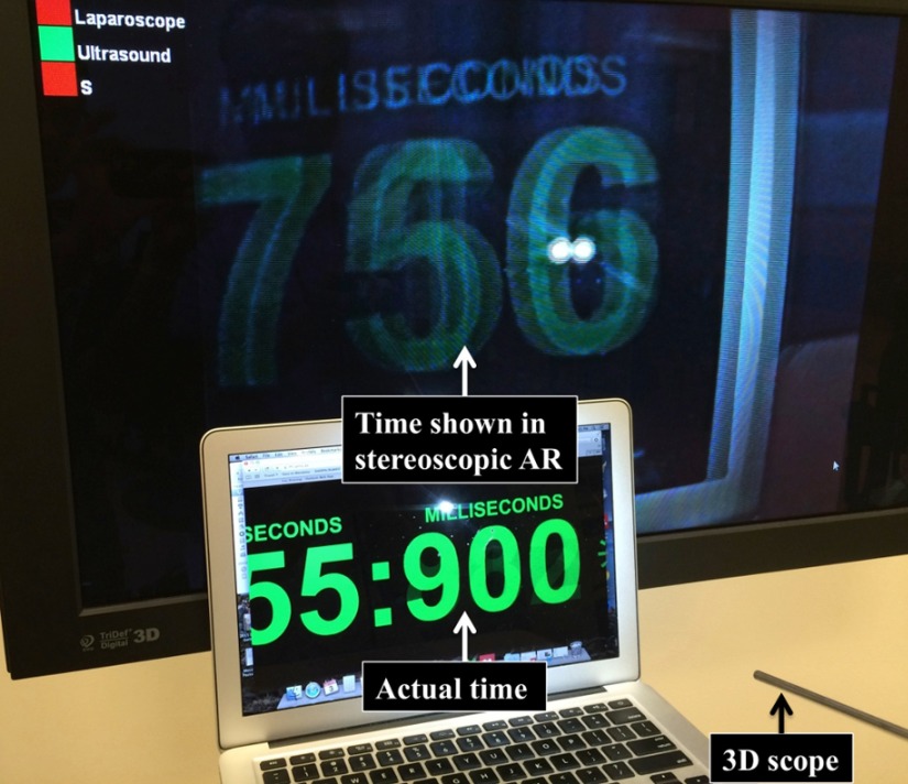
As shown in Fig. 9, we used the accepted method of imaging a high-speed digital clock with millisecond resolution to measure system latency. Any difference in the actual time and the time seen in the AR image is then the latency. Ultrasound overlay was kept on during this measurement to factor in video processing time needed for image fusion and stereoscopic AR visualization. The AR latency was measured to be . For comparison, we also measured the latency of the stereoscopic vision system alone, and the resulting latency was . Therefore, the EM-AR system contributed 58 ms delay to the overall latency. This contribution includes the time for video data streaming to the laptop and the time for stereoscopic AR processing. No perceptible latency was present in our AR visualization, as can also be seen in the submitted video clips.
Fig. 9.
Experiment setup to measure AR system latency.
3.5. Animal Study
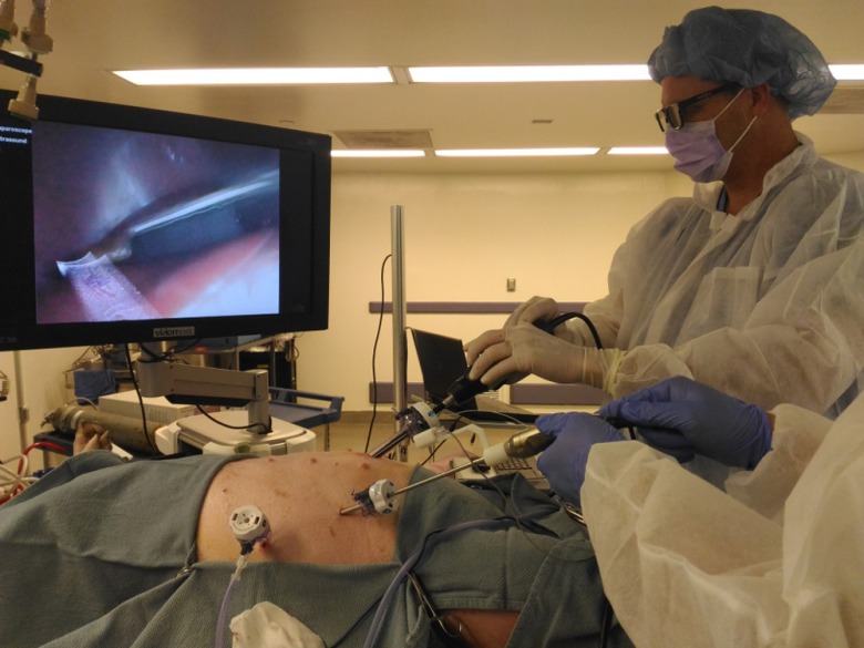
An animal procedure, approved by the Institutional Animal Care and Use Committee (IACUC), was conducted to test the system. As shown in Fig. 10, after successful anesthesia and intubation, a 40-kg female Yorkshire swine was placed in the supine position (face up) on a surgical pad, which was positioned on top of the EM tabletop field generator. The swine was positioned such that the EM sensor attached to the imaging tip of the LUS probe and the sensor attached to the handle of the 3-D laparoscope were within the working volume of EM tracking. A 12-mm trocar was placed at the midline midabdomen for introducing the LUS probe, and a 5-mm trocar was placed at the anterior axillary line in the lower abdomen for introducing the 3-D laparoscope. Carbon dioxide pneumoperitoneum at 10 mmHg was created. Liver, kidneys, and biliary structures were examined, with the real-time LUS images superimposed on the 3-D laparoscopic video to provide internal anatomical details of the organs.
Fig. 10.
Surgeons wearing polarized 3-D glasses and using the stereoscopic EM-AR system to visualize the internal anatomy of the swine.
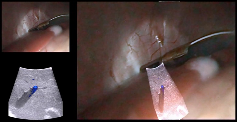
The stereoscopic EM-AR system was successfully used for visualization during the experiment. Subsurface anatomical structures along with vascular flow (using color Doppler mode of the ultrasound scanner) in the liver, kidney, and biliary system were clearly observed. Bending the imaging tip of the LUS probe did not affect the overlay accuracy. Even with rapid movements of the LUS probe, there was no perceptible latency for AR visualization. Two representative video clips of the animal study are provided as electronic supplementary material (Fig. 11).
Fig. 11.
Recorded videos during the animal study. The video shows the right-eye channel of live stereoscopic EM-AR visualization with ultrasound calibrated at the depth of 4.8 cm. The videos also show the original views of the laparoscope and the ultrasound. (Video 3, MP4, 12.2 MB [URL: http://dx.doi.org/10.1117/1.JMI.3.4.045001.3]; Video 4, MP4, 6.4 MB [URL: http://dx.doi.org/10.1117/1.JMI.3.4.045001.4].)
4. Discussion
In this work, we have developed a clinically viable laparoscopic AR system based on EM tracking. The performance of the EM-AR system has been rigorously validated to have clinically acceptable registration accuracy and visualization latency. We further evaluated the proposed system in an animal.
The overall image-to-video TRE of meets our accuracy target, which is half the resection margin (5 mm) sought in most tumor ablative procedures.29 This is better than our previously reported accuracy, i.e., and for the left- and right-eye channels, respectively, for the AR system based on optical tracking.9 This improvement could be attributed to placing the EM sensor closer to the imaging tip of the LUS probe, compared to attaching the optical marker on the handle of the LUS probe. Although it is intuitive to treat the 3-D scope as a stereo-camera system, our preliminary experiments suggested calibrating the 3-D scope in the stereo-camera mode might lead to larger TRE due to small separation between the left- and right-eye channels (1.04-mm interpupillary distance). Hence, the stereo-mode TRE may not truly reflect the calibration accuracy because a small error in calibration or corner point detection could get magnified and lead to a large TRE.
The overall stereoscopic EM-AR system latency was 177 ms. Prior studies focusing on robotic laparoscopic telesurgery have investigated the impact of increasing latency on surgical performance. There is not a fixed, agreed-upon threshold, a latency smaller than which is considered acceptable enough. For example, Kumcu et al.30 reported deterioration in the performance and user experience beyond a 105-ms system latency. Xu et al.31 claimed that the impact of latency on instrument manipulations was mild in the 0 to 200-ms range and that a less than 200-ms latency was ideal for telesurgery. Perez et al.32 reported a measurable deterioration in the performance beginning at a latency of 300 ms. Based on these results, our measured system latency is within a clinically acceptable range. As described earlier, the major contribution to the overall latency is from the Visionsense stereoscopic vision system, not the AR visualization itself. The overall latency should decrease as stereoscopic vision systems improve.
The system performance was maintained during the animal study. In the video clips from the animal study (Fig. 11), a qualitative assessment shows that the image-to-video registration accuracy was good but may be slightly lower compared to that in the laboratory studies (Fig. 6). The registration accuracy depends on the system calibration accuracy and EM tracking accuracy of the two sensors. Based on our experience, EM tracking is more accurate and robust when the sensor is placed closer to the center of the tabletop field generator. In our system, while one sensor is attached to the imaging tip of the LUS probe, the other is attached to the handle of the 3-D laparoscope. This arrangement requires care in ensuring that both sensors are close to the center of the field generator. For the animal study, the LUS probe and the 3-D laparoscope have to be inserted through fixed trocar locations, limiting the freedom with which the two imaging probes could be manipulated. Thus, the positioning of the animal on the field generator and the positioning of the trocars on the animal are important considerations to ensure accurate EM tracking and registration. We plan to further study these practical issues and optimize animal and trocar positions through additional animal experiments. The results of the first animal experiment, nonetheless, demonstrate the technical soundness of using the proposed EM-AR system in vivo.
The planned clinical workflow for using the EM-AR system is as follows. The AR system will be calibrated about a day in advance of each clinical use. It takes to calibrate the whole system to achieve acceptable accuracy. Then, the 3-D scope, the LUS probe, and the tracking mounts will be sent for sterilization. Finally, in the OR, the sterilized items will be reassembled at the beginning of the procedure. This workflow is feasible because the 3-D scope employed has no exchangeable optical parts, and our snap-on tracking mounts are capable of duplicating the sensor locations on the imaging probes as used during calibration. It should be noted that it is possible to extend our system to conventional 2-D laparoscopes. One difficulty with using conventional laparoscopes is that some optical parameters, e.g., the focal length, can be varied by the surgeon during a surgical procedure, rendering precalibration data unusable. A possible solution could be a fast and easy camera calibration method that can be performed during the procedure, and we have begun examining the accuracy of such a single-image calibration method.33 To extend the EM-AR system for human use, a sterile Laparoscopic Cover (Civco Medical Solutions, Kalona, Iowa) marketed specifically for the exact LUS transducer can be used.
In conclusion, we have developed a fully integrated, compact, and accurate stereoscopic AR visualization system based on EM tracking. The system was designed to meet several practical requirements and has the potential to be used clinically. The work described in this study is a critical step toward our broad, long-term goal of developing a practical EM-AR system by systematically addressing all technical issues facing routine implementation and conducting its clinical translation.
Supplementary Material
Acknowledgments
This work was supported in part by the National Institutes of Health Grant No. 1R41CA192504 (PI: Raj Shekhar). The authors would like to thank He Su and James McConnaughey for their help with designing and printing the EM tracking mounts. They are grateful to Emmanuel Wilson for his assistance in building the vascular ultrasound phantom.
Biographies
Xinyang Liu received his BE degree in electrical engineering from Beijing Institute of Technology in 2003, and his PhD in biomathematics from Florida State University in 2010. He is a staff scientist at the Children’s National Health System. His current research interests include medical augmented reality and computer-assisted surgery.
Sukryool Kang is a staff scientist in the Sheikh Zayed Institute for Pediatric Surgical Innovation at the Children’s National Health System. He works in the areas of digital image/signal processing and medical decision support systems based on machine learning. He received the PhD degree from University of California, San Diego in 2014.
William Plishker received the BS degree in computer engineering from Georgia Tech, Atlanta, Georgia and a PhD degree in electrical engineering from the University of California, Berkeley. His PhD research centered on application acceleration on network processors. His postdoctoral work at the University of Maryland included new dataflow models and application acceleration on graphics processing units. He is currently the CEO of IGI Technologies, Inc., which focuses on medical image processing.
George Zaki served as the chief science officer at IGI Technologies from 2013 to 2015, where he developed medical image processing tools for cancer treatments. He received his MSc and PhD degrees in computer engineering from University of Maryland (UMD), College Park, in 2012 and 2013 respectively. His research interests include model based design for DSP systems implemented on multiprocessor heterogeneous platforms, system acceleration using graphics processing units (GPUs), high performance computing, and embedded systems.
Timothy D. Kane is a principal investigator in the Sheikh Zayed Institute for Pediatric Surgical Innovation at the Children’s National Health System and professor of surgery and pediatrics in the George Washington School of Medicine and Health Sciences. He is chief of the Division of General and Thoracic Surgery at Children’s National Health System and is an expert on minimally invasive general and thoracic surgery in infants and children.
Raj Shekhar is a principal investigator in the Sheikh Zayed Institute for Pediatric Surgical Innovation at the Children’s National Health System and an associate professor of padiology and pediatrics in the George Washington School of Medicine and Health Sciences. He leads research and development in advanced surgical visualization, multimodality imaging, and novel mobile and pediatric devices. He was previously with the Cleveland Clinic and the University of Maryland and has founded two medical technology startups.
References
- 1.Himal H. S., “Minimally invasive (laparoscopic) surgery,” Surg. Endoscopy 16(12), 1647–1652 (2002). 10.1007/s00464-001-8275-7 [DOI] [PubMed] [Google Scholar]
- 2.Osborne D. A., et al. , “Laparoscopic cholecystectomy: past, present, and future,” Surg. Technol. Int. 15, 81–85 (2006). [PubMed] [Google Scholar]
- 3.Leven J., et al. , “DaVinci canvas: a telerobotic surgical system with integrated, robot-assisted, laparoscopic ultrasound capability,” Med. Image Comput. Comput. Assist. Interv. 8(Pt 1), 811–818 (2005). [DOI] [PubMed] [Google Scholar]
- 4.Feuerstein M., et al. , “Intraoperative laparoscope augmentation for port placement and resection planning in minimally invasive liver resection,” IEEE Trans. Med. Imaging 27(3), 355–369 (2008). 10.1109/TMI.2007.907327 [DOI] [PubMed] [Google Scholar]
- 5.Su L. M., et al. , “Augmented reality during robot-assisted laparoscopic partial nephrectomy: toward real-time 3D-CT to stereoscopic video registration,” Urology 73(4), 896–900 (2009). 10.1016/j.urology.2008.11.040 [DOI] [PubMed] [Google Scholar]
- 6.Teber D., et al. , “Augmented reality: a new tool to improve surgical accuracy during laparoscopic partial nephrectomy? Preliminary in vitro and in vivo results,” Eur. Urol. 56(2), 332–338 (2009). 10.1016/j.eururo.2009.05.017 [DOI] [PubMed] [Google Scholar]
- 7.Cheung C. L., et al. , “Fused video and ultrasound images for minimally invasive partial nephrectomy: a phantom study,” Med. Image Comput. Comput. Assist. Interv. 13(Pt 3), 408–415 (2010). [DOI] [PubMed] [Google Scholar]
- 8.Shekhar R., et al. , “Live augmented reality: a new visualization method for laparoscopic surgery using continuous volumetric computed tomography,” Surg. Endoscopy 24(8), 1976–1985 (2010). 10.1007/s00464-010-0890-8 [DOI] [PubMed] [Google Scholar]
- 9.Kang X., et al. , “Stereoscopic augmented reality for laparoscopic surgery,” Surg. Endoscopy 28(7), 2227–2235 (2014). 10.1007/s00464-014-3433-x [DOI] [PubMed] [Google Scholar]
- 10.Storz P., et al. , “3D HD versus 2D HD: surgical task efficiency in standardised phantom tasks,” Surg. Endoscopy 26(5), 1454–1460 (2012). 10.1007/s00464-011-2055-9 [DOI] [PubMed] [Google Scholar]
- 11.Smith R., et al. , “Advanced stereoscopic projection technology significantly improves novice performance of minimally invasive surgical skills,” Surg. Endoscopy 26(6), 1522–1527 (2012). 10.1007/s00464-011-2080-8 [DOI] [PubMed] [Google Scholar]
- 12.Mountney P., et al. , “Simultaneous stereoscope localization and soft-tissue mapping for minimal invasive surgery,” Med. Image Comput. Comput. Assist. Interv. 9(Pt 1), 347–354 (2006). [DOI] [PubMed] [Google Scholar]
- 13.Pratt P., et al. , “Robust ultrasound probe tracking: initial clinical experiences during robot-assisted partial nephrectomy,” Int. J. Comput. Assisted Radiol. Surg. 10(12), 1905–1913 (2015). 10.1007/s11548-015-1279-x [DOI] [PubMed] [Google Scholar]
- 14.Shekhar R., et al. , “Stereoscopic augmented reality visualization for laparoscopic surgery—initial clinical experience,” in Proc. Annual Meeting of the Society of American Gastrointestinal and Endoscopic Surgeons, Vol. 29(Suppl 1) (2015). [Google Scholar]
- 15.Nafis C., Jensen V., von Jako R., “Method for evaluating compatibility of commercial electromagnetic (EM) micro sensor tracking systems with surgical and imaging tables,” Proc. SPIE 6918, 691820 (2008). 10.1117/12.769513 [DOI] [Google Scholar]
- 16.Maier-Hein L., et al. , “Standardized assessment of new electromagnetic field generators in an interventional radiology setting,” Med. Phys. 39(6), 3424–3434 (2012). 10.1118/1.4712222 [DOI] [PubMed] [Google Scholar]
- 17.Franz A. M., et al. , “Electromagnetic tracking in medicine—a review of technology, validation, and applications,” IEEE Trans. Med. Imaging 33(8), 1702–1725 (2014). 10.1109/TMI.2014.2321777 [DOI] [PubMed] [Google Scholar]
- 18.Liu X., et al. , “Evaluation of electromagnetic tracking for stereoscopic augmented reality laparoscopic visualization,” in Proc. MICCAI Workshop on Clinical Image-based Procedures: Translational Research in Medical Imaging, pp. 84–91 (2014). [Google Scholar]
- 19.Moore J., et al. , “Integration of trans-esophageal echocardiography with magnetic tracking technology for cardiac interventions,” Proc. SPIE 7625, 76252Y (2010). 10.1117/12.844273 [DOI] [Google Scholar]
- 20.Feuerstein M., et al. , “Magneto-optical tracking of flexible laparoscopic ultrasound: model-based online detection and correction of magnetic tracking errors,” IEEE Trans. Med. Imaging 28(6), 951–967 (2009). 10.1109/TMI.2008.2008954 [DOI] [PubMed] [Google Scholar]
- 21.Tabaee A., et al. , “Three-dimensional endoscopic pituitary surgery,” Neurosurgery 64(5 Suppl 2), 288–293 (2009). 10.1227/01.NEU.0000338069.51023.3C [DOI] [PubMed] [Google Scholar]
- 22.Much J., “Error classification and propagation for electromagnetic tracking,” MS Thesis, Tech. Univ. Mänchen, Munich, Germany: (2008). [Google Scholar]
- 23.Johnson M., “Exploiting quaternions to support expressive interactive character motion,” PhD Dissertation, MIT, Cambridge, Massachusetts: (2003). [Google Scholar]
- 24.Bouguet J.-Y., “Camera calibration with OpenCV,” http://docs.opencv.org/doc/tutorials/calib3d/camera_calibration/camera_calibration.html (19 September 2016).
- 25.Shiu Y., Ahmad S., “Calibration of wrist-mounted robotic sensors by solving homogeneous transform equations of the form ax = xb,” IEEE Trans. Robot. Automat. 5(1), 16–29 (1989). 10.1109/70.88014 [DOI] [Google Scholar]
- 26.Lasso A., et al. , “PLUS: open-source toolkit for ultrasound-guided intervention systems,” IEEE Trans. Biomed. Eng. 61(10), 2527–2537 (2014). 10.1109/TBME.2014.2322864 [DOI] [PMC free article] [PubMed] [Google Scholar]
- 27.Hartley R., Sturm P., “Triangulation,” Comput. Vision Image Understanding 68(2), 146–157 (1997). 10.1006/cviu.1997.0547 [DOI] [Google Scholar]
- 28.Yaniv Z., et al. , “Ultrasound calibration framework for the image-guided surgery toolkit (IGSTK),” Proc. SPIE 7964, 79641N (2011). 10.1117/12.879011 [DOI] [Google Scholar]
- 29.Rutkowski A., et al. , “Acceptance of a 5-mm distal bowel resection margin for rectal cancer: is it safe?,” Colorectal Dis. 14(1), 71–78 (2012). 10.1111/codi.2011.14.issue-1 [DOI] [PubMed] [Google Scholar]
- 30.Kumcu A., et al. , “Effect of video lag on laparoscopic surgery: correlation between performance and usability at low latencies,” Int. J. Med. Robot. (2016). 10.1002/rcs.1758 [DOI] [PubMed]
- 31.Xu S., et al. , “Determination of the latency effects on surgical performance and the acceptable latency levels in telesurgery using the dV-Trainer®simulator,” Surg. Endoscopy 28(9), 2569–2576 (2014). 10.1007/s00464-014-3504-z [DOI] [PubMed] [Google Scholar]
- 32.Perez M., et al. , “Impact of delay on telesurgical performance: study on the robotic simulator dV-Trainer,” Int. J. Comput. Assisted Radiol. Surg. 11(4), 581–587 (2016). 10.1007/s11548-015-1306-y [DOI] [PubMed] [Google Scholar]
- 33.Liu X., et al. , “On-demand calibration and evaluation for electromagnetically tracked laparoscope in augmented reality visualization,” Int. J. Comput. Assisted Radiol. Surg. 11(6), 1163–1171 (2016). 10.1007/s11548-016-1406-3 [DOI] [PMC free article] [PubMed] [Google Scholar]
Associated Data
This section collects any data citations, data availability statements, or supplementary materials included in this article.


