Abstract
Fish-like, dolphin-like, and bionic nonsmooth surfaces were employed in a hydraulic torque converter to achieve drag reduction and performance improvement, which were aimed at reducing profile loss, impacting loss and friction loss, respectively. YJSW335, a twin turbine torque converter, was bionically designed delicately. The biological characteristics consisted of fish-like blades in all four wheels, dolphin-like structure in the first turbine and the stator, and nonsmooth surfaces in the pump. The prediction performance of bionic YJSW335, obtained by computational fluid dynamics simulation, was improved compared with that of the original model, and then it could be proved that drag reduction had been achieved. The mechanism accounting for drag reduction of three factors was also investigated. After bionic design, the torque ratio and the highest efficiencies of YJSW335 were both advanced, which were very difficult to achieve through traditional design method. Moreover, the highest efficiency of the low speed area and high speed area is 85.65% and 86.32%, respectively. By economic matching analysis of the original and bionic powertrains, the latter can significantly reduce the fuel consumption and improve the operating economy of the loader.
1. Introduction
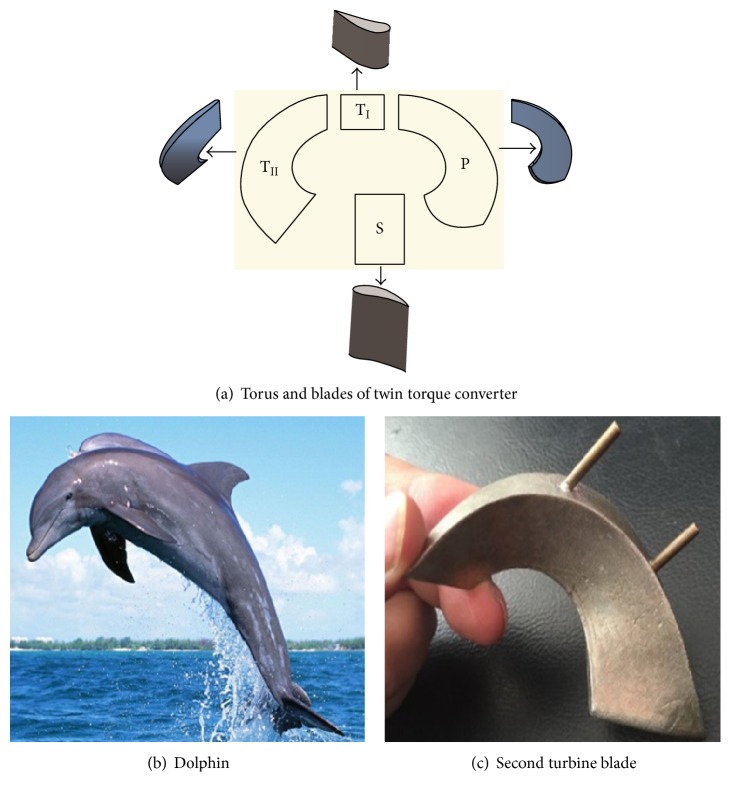
A hydraulic torque converter (torque converter or TC) is a kind of turbomachine that is widely used in automatic transmissions for automobiles and engineering machinery. In Figure 1(a), there is twin turbine torque converter, including four elements, pump (P), first turbine (TI), second turbine (TII), and stator (S). Torque converter always employs liquid as the medium. Efficiency is an important performance parameter for turbomachines. Denton pointed out that loss is defined in terms of entropy in turbomachines. In torque converter, the source of entropy is mainly from viscous effects in boundary layers [1]. The loss components in torque converter include friction loss, profile loss, and the impacting loss in leading edge of blade. Over the years, enormous efforts have been expended in trying to improve the performances of torque converter [2–4]. It is a key factor to decrease those losses to achieve the goal. The performance of torque converter is generally improved through optimizing the blade of the torque converter. Yan et al. found that the outlet radii of pump, turbine, and stator, the fluid density, and the outlet angle of the stator had the most significant influence on the performance [5]. Ejiri and Kubo established the relationship between geometric parameters and the flow loss of torque converter and reduced the loss through optimizing geometric parameters [6]. Cheng et al. developed the comprehensive optimization system of torque converter in which CFD, DOE, and RSM and other methods were integrated [7].
Figure 1.
Similarity between torque converter blade and dolphin.
The performances, especially efficiency improvement, can be reached by reducing the loss. Hence, drag reduction especially in boundary layer flow is significant for torque converter. Nature has created reducing drag ways in fluid flow. Fast fish and cetaceans swim in water with great agility. Efficient design is a common trait in nature, and many structures serve multiple purposes. Liao et al. showed a mechanism that swimming fish used environmental vortices to reduce the cost of locomotion [8]. Wu summed up some principal factors involved in fish locomotion, such as the body thickness, variations in body depth, and vortex shedding from dorsal. In general, nearly all fish bodies have a symmetry center plane, namely, the focal plane. A scheme known as the focal-plane singularity method had been quite actively applied in the naval hydrodynamics profession for studies on ship maneuvering and seakeeping in ocean waves [9]. The medial camber lines of shell and core of blades can be drawn as a plane just like focal plane in fish. The plane is significate for the blade design of torque converter. The thickness and its distribution along the medial camber line also highly decide the performance of torque converter.
In fact, the streamline bodies in fish, cetaceans, and blade aim to reduce the profile loss. Figures 1(b) and 1(c) show the similarity of blades and dolphin diving out of water. Natural transition occurs from laminar to turbulent flow regimes near a Reynolds number around 4000 for pipe flow and 500 000 for flow over a flat plate. In Gray's analysis of dolphin energetics and hydrodynamic, the dolphin's body was modelled as a one-sided flat plate; the corresponding Reynolds number based on body length was about 20 × 106 [10]. It means the flow over the dolphin's body would be mostly turbulent. The flow in torque converter is internal, and the Reynolds number varying from rotating speed is particularly difficult to quantify. In our previous study, it is can be above 105; hence the flows pass dolphin and torque converters are both turbulent [11]. Inspired by the focal plane and thickness of fish, it will help to reduce the profile loss in torque converter. Consequently the efficiency could be improved.
Another famous aquatic animal that possesses multipurpose skin is fast swimming sharks. Structures inspired from shape of the shark-skin riblets provided a maximum drag reduction of nearly 10%. The well-known commercial application of riblets is competition swimsuit. Saravi et al. reviewed the experimental applications of riblets to aerospace, automotive, and energy industries [12]. In Dean & Bhushan's review, riblet-performance studies were given, and optimal riblet geometries were defined. Two mechanisms of riblet drag reduction were shown. First, riblets impede the translation of the streamwise vortices. Second, riblets lift the vortices off the surface and reduce the amount of surface area exposed to the high-velocity flow [13].
Many kinds of bionic nonsmooth surfaces, like riblets and others, are already used in industrial flows to obtain drag reduction successfully [14–18]. Actually, the nonsmooth surfaces mainly achieve the drag reduction by decreasing the friction loss in boundary layers, which also have their potential drag reduction in torque converter.
The skin of the dolphin has also been studied for drag-reducing properties. Choi and Kulik proposed a dolphin-like compliant material on the surface of an object in a fluid flow and achieved 7% of drag reduction [19]. In addition, the structure of dolphin's head has obvious difference compared with its body, which contributes to reducing the impacting loss. The leading edge of torque converter' blade faces the similar situation of occurring severe impact. The nature structure of dolphin's head could inspire the design of torque converter.
As mentioned above, the aquatic animals achieve drag reduction by employing many factors. Hence the bionic coupling technology is the trend of engineering applications development [13]. Zhao et al. proposed a new type of hydrophobic model which was also consistent with the shark-skin-inspired microriblets. It was proved that the new model was necessary and important to explain drag reduction well [20]. Wang et al. designed a hydrophobic surface which was combined with transverse microgrooves. The friction resistance can be decreased owing to the air pockets kept by grooves [21]. In this paper, the focal plane and thickness of fish, the nonsmooth surfaces, and the structure of dolphin's head are combined together attempting to achieve drag reduction and improve the performances of torque converter, especially efficiency. The three factors are used to reduce the profile loss, friction loss, and impacting loss, respectively. Each factor has been proved that it possesses positive effect on drag reduction. However, considering published literatures, those factors or their combination is rarely applied in torque converter to obtain drag reduction.
2. Coupling Bionic Design Based CFD Simulation
The torque converter called YJSW335 is employed in this paper, which is a twin turbine torque converter consisting of a pump, a first turbine, a second turbine, and a stator. It should be pointed out that many kinds of fishes and parameters of blade are involved in the design. Computational fluid dynamics, usually abbreviated as CFD, is an effective method in design and optimization of torque converter which has been proved by many applications [22–25], and the cost of that is much less than the experiment. Hence, in the following section, a large number of calculations were conducted to choose the appropriate biological sample and structure for each element of torque converter.
2.1. Fish-Bionic
Except its focal plane and thickness, the body shape of the fish is consistently changed during swimming. In the fish-like bionic design process of the torque converter blade, the inlet and outlet angle were maintained constant. The focal plane and thickness obtained from fish body, rather than the body shape of fish, were applied to the blade.
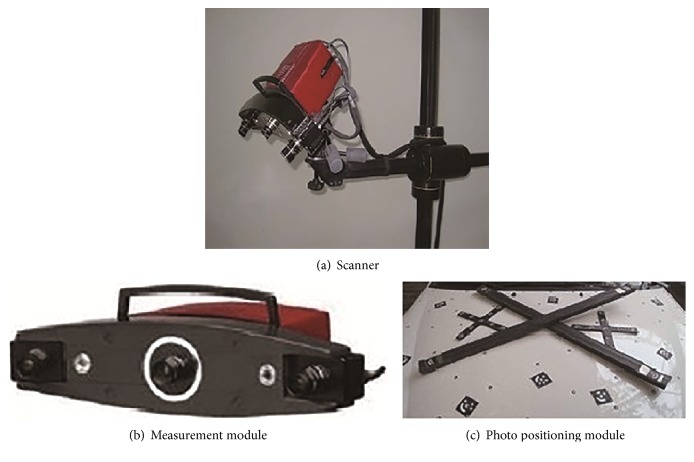
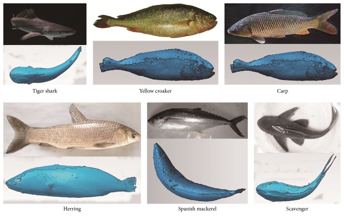
The body data of fish was measured by ATOS three-dimensional optical scanner (Figure 2). Before scanning, the pectoral fins, pelvic fins, and caudal fins were removed. The imaging agent was sprayed on the surface, and some small black dots were also put on as reference points. Multiple perspectives of scanning were accomplished to guarantee the accuracy of measurement. The same measure proceeded to scan the other side. Eventually the complete three-dimensional point cloud data of fish was obtained, which was imported into Geomagic Studio to rebuild the fish model. Figure 3 showed the six kinds of fish and corresponding scanned model. The points formed triangle surfaces which might be coarse. The surface quality was improved through smoothing, filling all the gaps, simplifying and removing the external points. Then, the whole surface was divided into small and quadrangled grids. To acquire the grid region of a quad face, a grid processing was proposed to make sure that the surface generated can represent the real lattice surface. After that, the face of NURBS was performed, fitted, and merged. Finally, it was exported as a STEP/IGES file, which could be imported into any CAD/CAM system. Figure 4 showed the process of Herring rebuilding.
Figure 2.
3D optical scanner camera system.
Figure 3.
Scanning data of fish and fish body.
Figure 4.
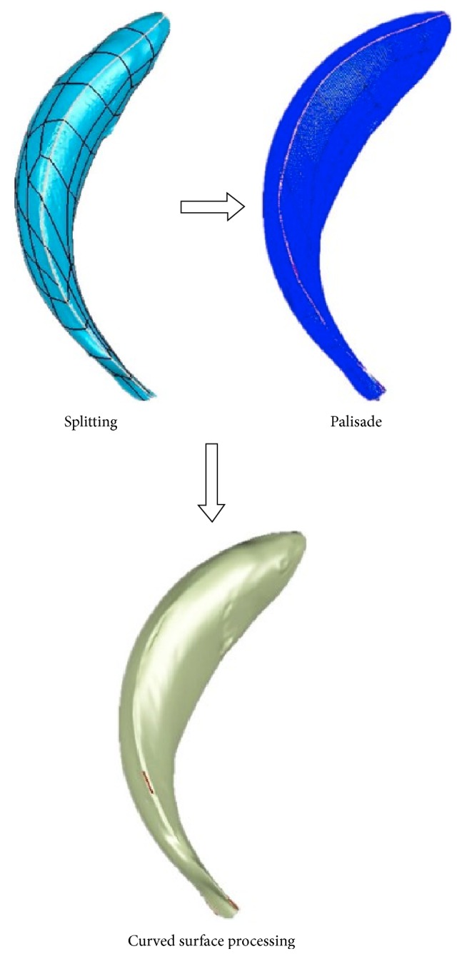
The reverse process.
The design process of bionic blade is described as follows briefly. As shown in Figure 5, the rebuilding tiger shark model was cut into three sections along height direction. The medial lines of the sections constituted the focal plane of fish, which were also considered as medial camber lines of blade. To design blade, the thickness and its distribution of fish should be extracted. As shown in Figure 6, the parameters of a section, such as the thickness distribution, the curvature along chord, and the inlet and outlet angles, were measured. A series of enveloping circles were made in each section so that they were tangential to the outline. The thickness distributions were extracted along height direction and the centers of circles constituted a medial camber line of blade.
Figure 5.
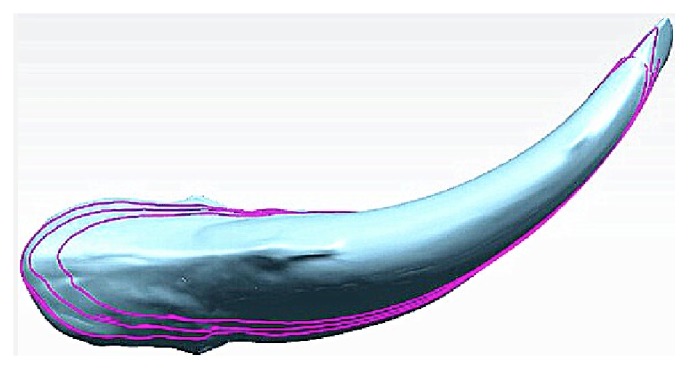
Rebuilding of tiger shark model.
Figure 6.
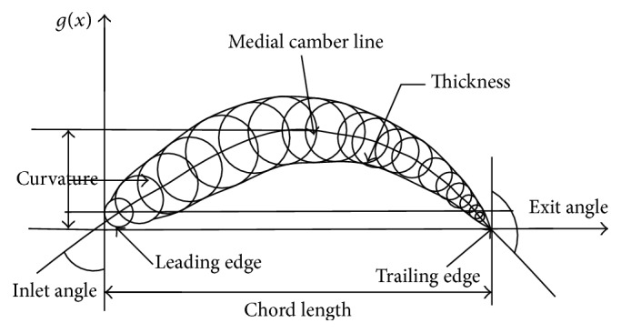
Parameters on the cross section.
The thickness ratio distributions from three sections are displayed in Figure 7, where c is chord and x is the length along the chord, so the abscissa is chord ratio, x ∈ [0, c]. The ordinate is thickness ratio, y is thickness, and y1 is thickness located at 10% chord length. The thickness ratios of the three sections are almost the same. The maximum thickness appeared at 30% length of the chord. The angles of three sections along the chord were shown in Table 1, where 0% and 100% represented the inlet angle and outlet angle, respectively. In Table 1, x/c is the length ratio along the chord, Q represents the angle, and the definition of it can be seen in Figure 6. The subscript number is the cross section of fish. CP is the change ratio of angle between two adjacent chord ratios. Based on the angles along the chord, circulation distribution can be calculated. The circulation distribution method is typically used in the design of torque converter's blade [26]. The prerequisite in the blade design is the estimation of the circulation from the inlet to outlet, which primarily determines the blade's shape. The circulation distribution rules of blades are mainly obtained through the empirical and experimental measurements. In this paper, bionic circulation distribution rule was established by extracting features from fish. Figure 8 displayed the value of the circulation distribution on medial camber line, the rules from shark, scavenger fish, and original were fitted through the polynomial, and the bionic blades were generated through the Matlab software.
Figure 7.
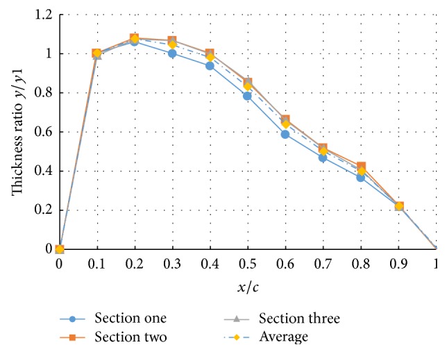
Three thickness ratios y/y1 of tiger shark.
Table 1.
Angle along the chord and its location of tiger shark.
| Chord ratio x/c |
1st group of angle Q1 |
2nd group of angle Q2 |
3rd group of angle Q3 |
Average value QP |
Proportion of offset angle CP |
|---|---|---|---|---|---|
| 0% | 53.44 | 53.66 | 53.9 | 53.67 | 0.00% |
| 10% | 53.82 | 54.27 | 54.5 | 54.2 | 0.58% |
| 20% | 55.16 | 55.4 | 56.65 | 55.74 | 1.70% |
| 30% | 58.16 | 61.53 | 61.41 | 60.37 | 5.10% |
| 40% | 75.09 | 73.43 | 71.57 | 73.36 | 14.32% |
| 50% | 85.64 | 84.76 | 87.82 | 86.07 | 14.00% |
| 60% | 101.6 | 99.51 | 98.61 | 99.91 | 15.24% |
| 70% | 110.17 | 108.37 | 108.22 | 108.9 | 9.93% |
| 80% | 122.2 | 119.93 | 119.46 | 120.5 | 12.79% |
| 90% | 136.73 | 132.12 | 132.32 | 133.7 | 14.53% |
| 100% | 144.44 | 144.76 | 144.69 | 144.6 | 12.01% |
Figure 8.
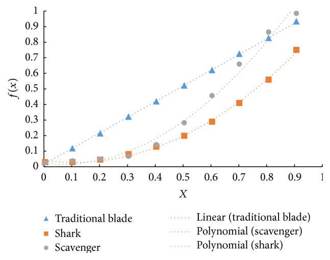
Fish and conventional stator blade distribution and polynomial fitting curve.
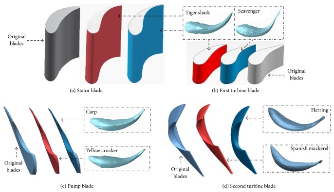
After CFD simulation, the bionic blades of YJSW335 were composed of second turbine from Spanish mackerel, stator blades from shark, the blades of the first turbine from scavenger, and the pump blades from carp, as shown in Figure 9.
Figure 9.
Comparison of bionic blades.
2.2. Dolphin Bionic Blade
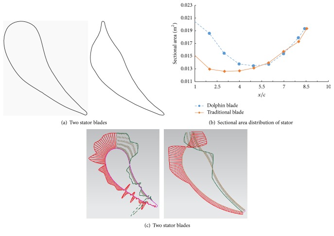
The dolphin-like bionic blade was shown in Figure 10(a). The main features of dolphin-like blade were described as follows. The inlet imitated the mouth of dolphin, which was thinner than that of the traditional one. Dolphin-like blade had a convex profile in the abdomen, and that of traditional blade was hollow. Concerning the curvature distribution, dolphin-like blade was superior to that of traditional blades.
Figure 10.
Comparison of traditional and bionic blades.
Figure 10(b) displayed the comparison of the flow section areas according to blades. The dolphin-like blade greatly reduced the change in the flow cross-sectional area, especially near the leading edge. The flow cross-sectional area in the whole passage was gentler; hence, except the impact loss, the diffusion and contraction loss was also decreased, which also could be proved by the smoother curvature distribution as shown in Figure 10(c). In it, the flow section areas of suction side were shown by the red line and that of pressure side was shown by the green line. The dolphin-like blades were applied in first turbine and stator due to only the fact that they possessed the plane sections; other wheels could not be designed like that due to the difficulty of manufacturing.
2.3. Nonsmooth Surface
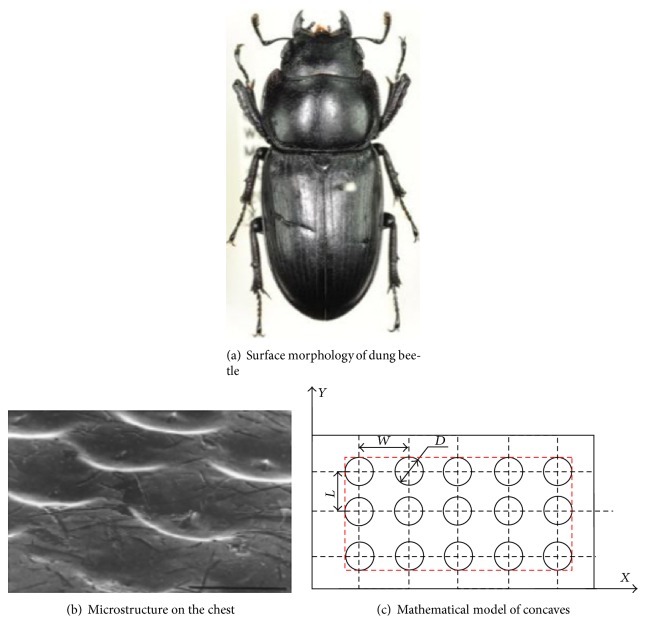
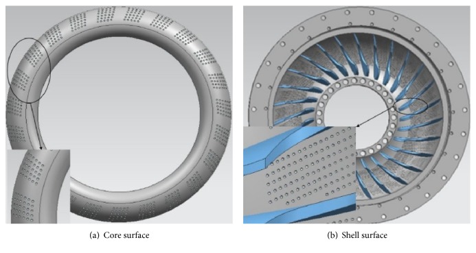
According to nonsmooth surfaces, Li et al. [27] established the mathematical models of bionic surfaces under four different arrangements with spherical concaves as the basic structural unit. A genetic algorithm was used to parse the biological concave morphology surface. The results showed that, in the circumstances of the same concaves density, the rectangular array showed the best drag reduction effect. Figures 11(a), 11(b), and 11(c) displayed surface morphology of dung beetle, microstructure on the chest, and the mathematical modelling of concave surface, respectively. For torque converter, the shell and core surfaces of pump wheel were designed in concaves with the rectangular configuration. The following factors were mainly taken into consideration: diameter D was 1 mm; radial spacing W was 3 mm; circumferential spacing L was 5 mm; the depth of concaves S was 0.5 mm. The core and shell surface were displayed in Figure 12.
Figure 11.
Nonsmooth surfaces of dung beetle.
Figure 12.
Nonsmooth pump model.
To sum up, the torque converter YJSW335 was bionically designed and made by Guangxi Liugong Machinery Co., Ltd. Comparing with the performances of original and bionic torque converter, the bioinspired design was assessed by CFD simulation. In the torque converter, fish circulation distributions were obtained and used in blades' design. The fish-like bionic blade group is composed of second turbine from Spanish mackerel, stator blades from shark, first turbine from scavenger, and pump from carp. Inspired by head of dolphin, the first turbine and stator were designed as dolphin-like structure. The nonsmooth surfaces were implied on the core and shell surfaces of pump. The fish morphology, the dolphin shape, and nonsmooth bionic surface were integrated to form the torque converter with multiple biological characteristics.
3. Performance Prediction for Three Coupling Bionic Factors
The Detached Eddy Simulation (DES) method was adopted to numerically calculate three-dimensional flow. Our previous study has verified the effectiveness of DES method, which is an appropriate and effective CFD model for the performance prediction of torque converter. The errors between computation and experiment are basically less than 5% [11]. Considering the logical coherence in this paper, detailed calculation process of DES turbulence model is not repeated.
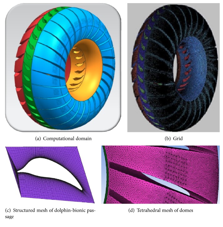
The whole flow passage was chosen as computational domain and the hybrid nonstructured grids with triangular prism were formed by ANSYS ICEM. Figure 13 displayed flow passage, the mesh, local tetrahedral mesh of pump shell, and structured mesh of dolphin-bionic passage. Because of the huge computation load of grids, only some of the concaves on bionic shell were selected in the numerical calculation. The total grid number is 1,908,061 and the pump cell number is 856,464.
Figure 13.
Tetrahedral mesh of pump and domes.
ANSYS FLUENT was employed to calculate the internal flow field. During the calculation, it was assumed that the pump and the turbine rotate along the gird interface according to a certain time step size (0.0005 s). The density and viscosity of the working medium were considered as constant and the leaking between the elements was ignored. In the solution, the change in the mass flow rate in two consecutive circulatory iterations in mass and momentum conservation equations was considered and all normalized residuals were less than 10−4. The properties of the CFD model were summarized in Table 2.
Table 2.
CFD model description.
| Analysis Type | Transient state |
| Turbulence model | Detached Eddy Simulation |
| Pressure-velocity coupling | SIMPLE |
| Transient formulation | Second-order implicit |
| Pump status | Fixed at 2000 rpm |
| Turbine status | Varied from 0~2000 rpm |
| Stator status | Stationary |
| Viscosity | 0.0258 Pa·s |
| Density | 860 kg/m3 |
3.1. Results and Discussion
Rothalpy was employed to evaluate the loss quantitatively. It would be a constant along a streamline for the ideal flow. However, for viscous flow the difference between two points in same line represented the hydraulic loss. It was defined as
| (1) |
where R, P, ρ, ω, and uc were the Rothalpy, pressure, density, relative velocity, and circumferential velocity, respectively.
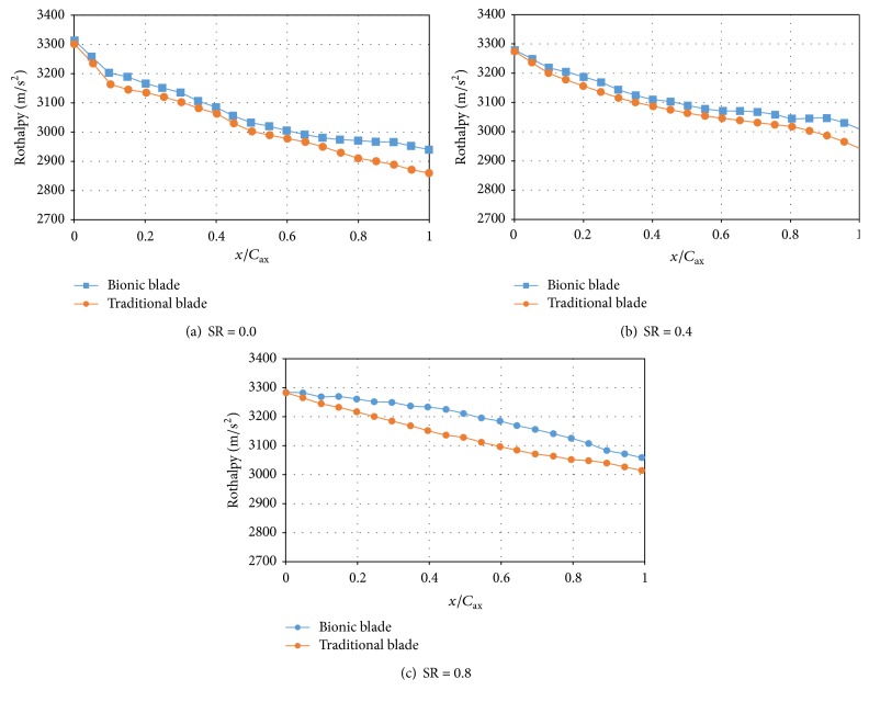
The changes of Rothalpy, from inlet to outlet on shell of pump and under different speed ratios (SR = 0, 0.4, 0.8; it equals to second turbine rotating speed divided by that of pump), were showed in Figure 14. The 0 and 1 in abscissa represented the leading edge and the trailing edge. The hydraulic loss in the inlet region (0~0.2) was serious due to the impact loss, which can be directly decreased through bionic design. The strong jet/wake characteristics including backflows and circulatory secondary flows were the key factors of hydraulic loss in main flow region (0.2–0.8). Complex flow including the free stream flow, blades wake flow, and core-suction corner separation in the outlet region were the loss in the trailing edge (0.8–1.0). For this reason, hydraulic losses were difficult to quantify. The loss in bionic torque converter obviously reduced by the changes of Rothalpy in any work condition compared with that of traditional.
Figure 14.
Rothalpy distribution of the pump from inlet to outlet under three conditions.
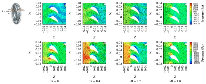
Figure 15 showed the pressure-velocity distribution on the surfaces of traditional stator and dolphin-like blades at different speed ratios (SR = 0, 0.4, 0.7, 1). The blocking effect on the leading edge which possessed the head of dolphin was reduced significantly. Correspondingly, the flow speed was increased. Pressure distribution of the blade leading edge was relatively balanced. The pressure difference between pressure side and suction side of blade was clearly decreased in any SR, which not only could reduce the impact loss but also would relieve the unsteady flow phenomena, such as secondary flow. Obviously, the flow on the leading edge had been reasonably improved.
Figure 15.
Pressure-velocity vector distribution on suspension of stator on SR = 0.4.
A vortex is a circular or spiral set of streamlines; a vortex core is a special type of isosurface that displays a vortex. Q-Criterion is the second invariant of the velocity gradient tensor, and it is used as recognition of vortex standard extensively. It is defined as
| (2) |
where Ω is vortex tensor and S is strain rate tensor.
Q also could be simplified as
| (3) |
As shown in Figure 16, the diffusion range and the intensity of the vortices at the inlet of pump were relatively large. The vortices were of dynamic motion and behaved irregularly. Generally, the vortex was initiated by the velocity gradient of liquid flow in the flow field. In other words, the gradient of velocity would contribute to vortex occurring. The vortex structures on the A and B regions in both bionic bade (Figure 16(a)) and traditional blade (Figure 16(b)) were compared, where A was nonsmooth region and B was adjacent upstream smooth region. As shown in Figure 16(b), the vortex in the region B maintained the flow state of the upstream vortex which was large and had little change. In contrast, the velocity gradient in Figure 16(a) was obviously decreased. As a result of interference effect of nonsmooth surface, the vortex structure of large scale was broken and the vortex type was no longer explicit. Some small-scale irregular vortices scattered, thus inhibiting the vortex generation, achieving the suppression of bursting phenomenon, and ultimately reducing the energy loss.
Figure 16.
Structure on vortex core region.
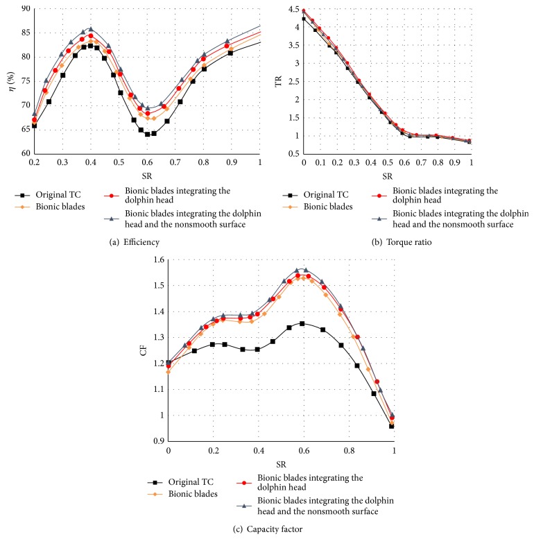
A key factor to evaluate the bionic design in this paper is the overall performance of torque converter. The obtained performances were shown in Figure 17 including η (efficiency), TR (torque ratio), and CF (capacity factor), respectively. The TR was 4.478 (SR = 0), which was 4.87% higher than that of the original blade. In addition, the highest efficiencies of the low speed area and high speed area were, respectively, 85.65% and 86.32%, which were, respectively, 3.28% and 3.16% higher than that of the original blade. The highest efficiencies of the low and high speeds were over 85%, which was very difficult to achieve via traditional design method. In this paper, the bionic design with the multiple biological features greatly improved the performance of the torque converter.
Figure 17.
Performance prediction of three coupling factors.
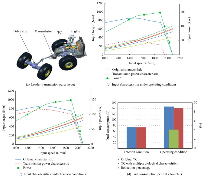
The improvement of torque converter YJSW335 could reduce the fuel consumption of a loader when it was equipped in the powertrain. The prediction model of wheel loader, which was used to calculate the vehicle performance, had been established in our previous work [28]. Economic matching analysis of the engine with original and bionic torque converters was conducted, respectively, and the fuel consumption was also calculated to evaluate the improvement of performances. The results of fuel consumption per 100 km under the traction and operation conditions were shown in Figure 18. Under the same traction conditions, the fuel consumption of the powertrain with bionic torque converter was about 4.02% lower than that with original torque converter. The result indicated that the multiple biological characteristics could significantly reduce the fuel consumption and improve the operating economy of the loader.
Figure 18.
Fuel consumption of loader with multiple biological characteristics.
4. Conclusion
This paper presented an idea that drag reduction and performance improvement could be realized through controlling the flow conditions in torque converter according to multiple biological characteristics including fish-like, dolphin-like, and bionic nonsmooth surface. The fish-like bionic blade group is composed of second turbine from Spanish mackerel, stator blades from shark, first turbine from scavenger, and pump from carp. Inspired by head of dolphin, the first turbine and stator were designed as dolphin-like structure. The nonsmooth surfaces were implied on the core and shell surfaces of pump.
The whole performance of torque converter was improved significantly by multiple bionic designs. The mechanism of drag reduction showed that fish-like, dolphin-like, and bionic nonsmooth surfaces reduced profile loss, impacting loss and friction loss. The torque ratio and the highest efficiencies were both advanced. The highest efficiency of the low speed area and high speed area was 85.65% and 86.32%. Both of them were over 85%, which indicated the bionic torque converter was in a high level. The bionic design also had a positive effect on reducing fuel consumption in the powertrain system equipped with bionic torque converter.
In the paper, when we conducted the internal flow filed simulation of torque converter, the density and viscosity of the working medium were considered constant which is different from the actual work. The leakage between two elements also should be calculated in the following work. Another very import issue is that the experiment should be conducted to verify the bionic design. We notice that many factors are involved in the torque converter; however, limited biological system or structure is analyzed; hence excellent biological structures need to be explored. Mathematical method, such as multiobjective optimization, can be used to find an optimal structure based on multiple biological characteristics.
Acknowledgments
This work was supported by China Postdoctoral Science Foundation (2016M590261) and Jilin Province Postdoctoral Foundation.
Competing Interests
The authors declared that there was no conflict of interests regarding the publication of this paper.
References
- 1.Denton J. D. Loss mechanisms in turbomachines. Proceedings of the ASME International Gas Turbine and Aeroengine Congress and Exposition; May 1993; Cincinnati, Ohio, USA. American Society of Mechanical Engineers; [Google Scholar]
- 2.Ejiri E., Kubo M. Influence of the flatness ratio of an automotive torque converter on hydrodynamic performance. Journal of Fluids Engineering. 1999;121(3):614–620. doi: 10.1115/1.2823513. [DOI] [Google Scholar]
- 3.Dong Y., Korivi V., Attibele P., et al. SAE Technical Paper. 2002-01-0883. SAE International; 2002. Torque converter CFD engineering part I: torque ratio and K factor improvement through stator modifications. [Google Scholar]
- 4.Jung J. H., Kang S., Hur N. A numerical study of a torque converter with various methods for the accuracy improvement of performance prediction. Progress in Computational Fluid Dynamics. 2011;11(3-4):261–268. doi: 10.1504/pcfd.2011.041027. [DOI] [Google Scholar]
- 5.Yan Q., Liu C., Wei W., Liu B. Numerical sensitivity analysis of the effect of pump outlet radius on the performance of torque converter. Proceedings of the FISITA 2012 World Automotive Congress; 2013; Beijing, China. Springer; [Google Scholar]
- 6.Ejiri E., Kubo M. Performance analysis of automotive torque converter elements. Journal of Fluids Engineering. 1999;121(2):266–275. doi: 10.1115/1.2822201. [DOI] [Google Scholar]
- 7.Cheng L., Xin P., Qing-Dong Y., Wei W. Effect of Blade Number on Performance of Torque Converter and Its Optimization Based on DOE and Response Surface Methodology. Transactions of Beijing Institute of Technology; 2012. [Google Scholar]
- 8.Liao J. C., Beal D. N., Lauder G. V., Triantafyllou M. S. Fish exploiting vortices decrease muscle activity. Science. 2003;302(5650):1566–1569. doi: 10.1126/science.1088295. [DOI] [PubMed] [Google Scholar]
- 9.Wu T. Y. Fish swimming and bird/insect flight. Annual Review of Fluid Mechanics. 2011;43:25–58. [Google Scholar]
- 10.Gray J. Studies in animal locomotion. Journal of Experimental Biology. 1933;10(1):88–104. [Google Scholar]
- 11.Liu C., Liu C., Ma W. Rans, detached Eddy simulation and large Eddy simulation of internal Torque converters flows: a comparative study. Engineering Applications of Computational Fluid Mechanics. 2015;9(1):114–125. doi: 10.1080/19942060.2015.1004814. [DOI] [Google Scholar]
- 12.Saravi, Sayad S., Cheng K. A review of drag reduction by riblets and micro-textures in the turbulent boundary layers. European Scientific Journal. 2013;9(33) [Google Scholar]
- 13.Dean B., Bhushan B. Shark-skin surfaces for fluid-drag reduction in turbulent flow: a review. Philosophical Transactions of the Royal Society of London A: Mathematical, Physical and Engineering Sciences. 2010;368(1929):4775–4806. doi: 10.1098/rsta.2010.0201. [DOI] [PubMed] [Google Scholar]
- 14.Boomsma A., Sotiropoulos F. Riblet drag reduction in mild adverse pressure gradients: a numerical investigation. International Journal of Heat and Fluid Flow. 2015;56:251–260. doi: 10.1016/j.ijheatfluidflow.2015.07.022. [DOI] [Google Scholar]
- 15.Chamorro L. P., Arndt R. E. A., Sotiropoulos F. Drag reduction of large wind turbine blades through riblets: evaluation of riblet geometry and application strategies. Renewable Energy. 2013;50:1095–1105. doi: 10.1016/j.renene.2012.09.001. [DOI] [Google Scholar]
- 16.Bixler G. D., Bhushan B. Shark skin inspired low-drag microstructured surfaces in closed channel flow. Journal of Colloid and Interface Science. 2013;393(1):384–396. doi: 10.1016/j.jcis.2012.10.061. [DOI] [PubMed] [Google Scholar]
- 17.Song X.-W., Zhang G.-G., Wang Y., Hu S.-G. Use of bionic inspired surfaces for aerodynamic drag reduction on motor vehicle body panels. Journal of Zhejiang University—SCIENCE A. 2011;12(7):543–551. doi: 10.1631/jzus.a1000505. [DOI] [Google Scholar]
- 18.Zhou H., Wang G., Ding Y., Yang J., Zhai H. Investigation of the effect of dimple bionic nonsmooth surface on tire antihydroplaning. Applied Bionics and Biomechanics. 2015;2015:10. doi: 10.1155/2015/694068.694068 [DOI] [PMC free article] [PubMed] [Google Scholar]
- 19.Choi K. S., Kulik V. M. Turbulent drag reduction using compliant surfaces. Proceedings of the Royal Society A Mathematical Physical and Engineering Sciences. 1997;453(1965):2229–2240. doi: 10.1098/rspa.1997.0119. [DOI] [Google Scholar]
- 20.Zhao D., Tian Q., Wang M., Jin Y. Study on the hydrophobic property of shark-skin-inspired micro-riblets. Journal of Bionic Engineering. 2014;11(2):296–302. doi: 10.1016/S1672-6529(14)60046-9. [DOI] [Google Scholar]
- 21.Wang B., Wang J.-D., Chen D.-R. Drag reduction on hydrophobic transverse grooved surface by underwater gas formed naturally. Acta Physica Sinica. 2014;63(7) doi: 10.7498/aps.63.074702.074702 [DOI] [Google Scholar]
- 22.Dong Y., Lakshminarayana B., Maddock D. Steady and unsteady flow field at pump and turbine exits of a torque converter. Journal of Fluids Engineering. 1998;120(3):538–548. doi: 10.1115/1.2820696. [DOI] [Google Scholar]
- 23.Kim B. S., Ha S. B., Lim W. S., Cha S. W. Performance estimation model of a torque converter part I: correlation between the internal flow field and energy loss coefficient. International Journal of Automotive Technology. 2008;9(2):141–148. doi: 10.1007/s12239-008-0018-5. [DOI] [Google Scholar]
- 24.Jung J. H., Kang S., Hur N. A numerical study of a torque converter with various methods for the accuracy improvement of performance prediction. Progress in Computational Fluid Dynamics. 2011;11(3-4):261–268. doi: 10.1504/PCFD.2011.041027. [DOI] [Google Scholar]
- 25.Kubota T., Kobayashi T., Saga T., et al. Application study of PIV measurement of flow field around lock-up clutch of automotive torque converter. JSAE Review. 2003;24(4):425–430. doi: 10.1016/S0389-4304(03)00078-X. [DOI] [Google Scholar]
- 26.Liu W., Liu C., Wang Q., Ma W., Chu Y. Design method of torque converter blade based on quadratic function distribution. Transactions of the Chinese Society of Agricultural Machinery. 2008;39(8):145–148. [Google Scholar]
- 27.Li J. Q., Tao M., Cui Z. R. Optimal design for pit bionic non-smooth surface of plate based on genetic algorithm. Proceedings of the 7th Asia-Pacific Conference of the International Society for Terrain-Vehicle Systems; 2004; Changchun, China. pp. 435–443. [Google Scholar]
- 28.Ma W., Zhang Y., Liu C., Wang S. Prediction method of the fuel consumption of wheel loaders in the V-type loading cycle. Mathematical Problems in Engineering. 2015;2015:12. doi: 10.1155/2015/538176.538176 [DOI] [Google Scholar]


