Abstract
Purpose:
To present a system for robotic 4D ultrasound (US) imaging concurrent with radiotherapy beam delivery and estimate the proportion of liver stereotactic ablative body radiotherapy (SABR) cases in which robotic US image guidance can be deployed without interfering with clinically used VMAT beam configurations.
Methods:
The image guidance hardware comprises a 4D US machine, an optical tracking system for measuring US probe pose, and a custom-designed robot for acquiring hands-free US volumes. In software, a simulation environment incorporating the LINAC, couch, planning CT, and robotic US guidance hardware was developed. Placement of the robotic US hardware was guided by a target visibility map rendered on the CT surface by using the planning CT to simulate US propagation. The visibility map was validated in a prostate phantom and evaluated in patients by capturing live US from imaging positions suggested by the visibility map. In 20 liver SABR patients treated with VMAT, the simulation environment was used to virtually place the robotic hardware and US probe. Imaging targets were either planning target volumes (PTVs, range 5.9–679.5 ml) or gross tumor volumes (GTVs, range 0.9–343.4 ml). Presence or absence of mechanical interference with LINAC, couch, and patient body as well as interferences with treated beams was recorded.
Results:
For PTV targets, robotic US guidance without mechanical interference was possible in 80% of the cases and guidance without beam interference was possible in 60% of the cases. For the smaller GTV targets, these proportions were 95% and 85%, respectively. GTV size (1/20), elongated shape (1/20), and depth (1/20) were the main factors limiting the availability of noninterfering imaging positions. The robotic US imaging system was deployed in two liver SABR patients during CT simulation with successful acquisition of 4D US sequences in different imaging positions.
Conclusions:
This study indicates that for VMAT liver SABR, robotic US imaging of a relevant internal target may be possible in 85% of the cases while using treatment plans currently deployed in the clinic. With beam replanning to account for the presence of robotic US guidance, intrafractional US may be an option for 95% of the liver SABR cases.
Keywords: ultrasound imaging, image guidance, robotic, intra-fractional, radiotherapy
1. INTRODUCTION
Image-guided liver stereotactic ablative body radiotherapy (SABR) has emerged as a safe and effective noninvasive treatment option for patients with inoperable liver tumors.1 Realizing the full potential of liver SABR by minimizing normal tissue irradiation and maximizing tumor dose is contingent on having the clinical capabilities to adequately manage respiratory-induced quasiperiodic liver motion.2,3 Abdominal compression techniques have been investigated to reduce respiratory liver motion, but in the majority of patients (60%) the magnitude of motion reduction is clinically not significant (<3 mm).4 In a different approach, respiratory gating2,5 or tracking6 is being used to minimize the effect of liver motion on dosimetric coverage while keeping the volume of irradiated normal liver low. Since real-time soft-tissue imaging is lacking on current LINAC systems, fluoroscopy imaging or electromagnetic tracking of fiducials implanted in the liver has been used to guide respiratory gating.5,7–10 However, the targeting accuracy with fiducials depends on marker-tumor distance11 and thus substantial errors may occur if the fiducials are not placed in proximity to the target lesion.12 Other concerns with this approach include: unaccounted respiratory-induced liver deformation, the need for fiducial implantation in inoperable patients, imaging dose for continuous intrafractional imaging, and artifacts on follow-up MR imaging with implanted electromagnetic markers.
We previously introduced a concept for an add-on telerobotic ultrasound (US) soft-tissue image guidance system as a possible alternative to fiducial-based intrafractional imaging13 and we demonstrated that with planar (2D) US imaging this system could be used for intrafractional monitoring of prostate displacements.14 We have subsequently developed a second generation system that employs an improved US probe-holding robot and a matrix array US transducer to provide operator-free soft-tissue real-time 3D (4D) imaging for abdominal sites of relevance to radiotherapy: prostate, liver, kidney, and pancreas. We have further evaluated and optimized the image-guidance system in volunteers in preparation for its use in patients.
Appropriate management of interferences of US image guidance hardware (robotic manipulator and US probe) with delivery devices and radiation beams is a prerequisite to deployment of intrafractional real-time US image guidance in patients. One approach is to optimize and calculate the dose distributions in patients with proper modeling of entrance beam perturbations introduced by the hardware.15 While dosimetrically feasible, this approach is a substantial departure from current clinical practice and it is yet unknown whether it is sustainable in the long term in view of radiation damage to the US transducer. Alternatively, treatment plan designs with noninterfering entrance beam arrangements can be pursued. Previous studies suggested that for the majority of prostate and liver SBRT patients, such clinically acceptable plans would be possible with abdominal placement of the US probe.16,17 The general design in these investigations was to introduce a probe model in the planning CT and replan a virtual treatment to achieve the initial dosimetric objectives. However, interferences with the robotic arm that would keep the probe in place were not considered and the selection of the probe location on the CT-segmented body was done only with visual assessment of the suitability of this location for US imaging—that is, with no quantifiable probe location metrics. Furthermore, while showing feasibility, the studies did not describe tools or workflow to support the clinical implementation of the interference-avoidance approach.
In this paper we introduce the current iteration of our robotic system for remote 4D US imaging and the associated tools to address the limitations of the studies discussed above. We present initial pilot data from a prospective patient study performed with the system in the treatment simulation setting and we evaluate retrospectively the proportion of liver SABR patients for whom robotic US imaging can be deployed without interference in clinical volumetrically modulated arc therapy (VMAT) plans. The novelty of the work is in: (1) the design and demonstration of a specialized robotic US manipulator for radiotherapy, (2) the generation and use of a simulated target visibility map (TVM) to guide the placement of the imaging probe for best target visualization in US while avoiding interference between the imaging hardware and the treatment beams, (3) introduction of a simulation environment and workflow for avoiding interferences between the delivery and the imaging system, and (4) first-in-patient implementation.
2. METHODS AND MATERIALS
2.A. Robotic US manipulator
2.A.1. Kinematics
Figure 1 depicts the 9-degree of freedom (DOF) robotic manipulator design. A base frame [gold, Fig. 1(a)] mounts to the medial plane of the treatment couch surface and attaches to the robot via a quick release clamp. Robot DOFs 1–3 are rotational joints forming a plastic wrist that primarily specifies probe orientation. DOFs 4–5 primarily specify probe position on the patient surface, and DOF 6 is a rotational joint coupled to a series-elastic transmission for controlling probe force (Sec. 2.C). DOFs 7–9 are redundant degrees of freedom to accommodate varying patient body sizes and varying US imaging positions against the abdomen. Figures 1(b)–1(d) show how the robotic manipulator is generally confined to operate within a safe zone with respect to the LINAC and CT physical workspace.
FIG. 1.
Robot design and kinematics. (a) CAD rendering with DOF labels. [(b)–(d)] illustrate the workspace of the LINAC and CT gantry as well as safe zones that ensure collision-free operation of the robot.
2.A.2. Operating principle
In order to minimize technology adoption barriers, the traditional process of US imaging is mimicked as closely as possible. During probe placement, the user grips the US probe and places the probe manually in imaging position against the patient abdomen while the robot remains passive. Once an appropriate imaging position is achieved the user pushes the robot’s “Image” button, the robot automatically maintains the selected probe position while controlling a consistent probe force against the patient abdomen. Due to the volumetric nature of 3D US, the probe’s position does not need to be continuously adjusted once an appropriate imaging position is found, as a single 3DUS probe pose is able to capture 3D internal anatomy motions within the field of view. For this reason, electromagnetic brakes (Ogura PMB Model 03 6-watt permanent magnet) are used to lock and unlock DOFs 1–5 instead of controlling the joints with electric motors or active actuators. The electromagnetic brakes have several advantages over motors including lower weight, higher holding force, and inherently higher safety because they are passive devices. DOF 6 is the only joint controlled actively via a motor, since consistent force control helps maintain acoustic contact. DOFs 7–9 are locked with manual levers, as these DOFs are set at the start of the procedure according to patient size and gross tumor area. The robot’s “Release” button causes the electromagnetic brakes (DOF 1–5) and force control (DOF 6) to release, enabling the US probe to be repositioned manually.
To facilitate reproducing a certain US imaging configuration, the robot can store position and pressure used in a given imaging session. For a subsequent session, the electromagnetic brakes freely rotate while the user manually brings the probe toward the position previously saved. As each joint matches its saved position, each corresponding electromagnetic brake locks into place until all joints are locked and the probe matches its saved position. At this point, automatic force control is activated such that the robot achieves the same base configuration and force between planning and treatment phases. If needed, minor adjustments to US probe base position can be made to optimize image quality by pressing the robot’s Release button and manually repositioning the probe.
2.A.3. CT compatibility
In some US-guided radiotherapy workflows, a radiolucent dummy18 or functional19 US probe can be used to apply abdominal pressure and/or capture US images during the planning CT scan. To accommodate this potential scenario, the area of the horizontal manipulator “boom” shaded in Fig. 2(a) is built with radiolucent plastics. The radiolucent area extends proximally away from the manipulator’s wrist in order to account for the situation shown in Fig. 2(b), where the probe is imaging a deep target and pitched back toward the manipulator base and CT imaging beam passes through the robot. The radiolucent design is achieved by coupling remotely located brakes and sensors containing metal [labeled 1, 2, and 3 in Fig. 2(a)] to the plastic wrist via a cabling system rigged with a synthetic cable. Figure 2(c) shows the system of plastic pulleys inside the wrist that redirects cables that couple motion of the three wrist axes to the three remote brake/sensor axes.
FIG. 2.
Metal-less low-profile cable driven wrist. (a) Horizontal manipulator boom with radiolucent area shaded in green. (b) Illustration of imaging geometry resulting in a CT imaging beam passing through the boom. (c) Internal cable pulley system. (d) Overhead views of the wrist in right-handed and left-handed configurations.
2.A.4. Series elastic force controller
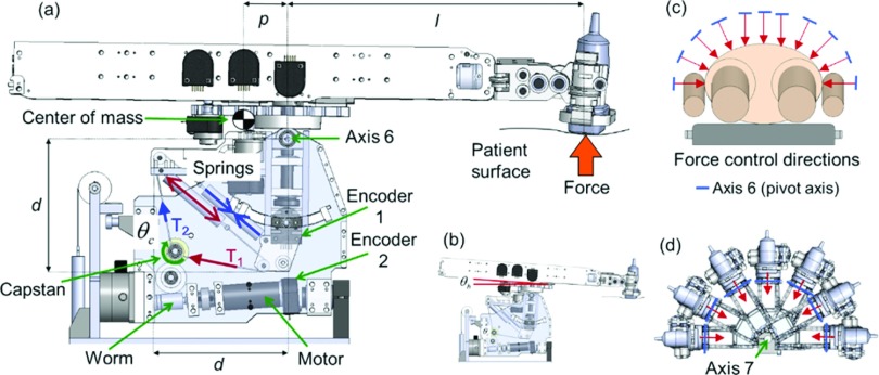
The force of the US probe against the patient is determined by the torque exerted about axis 6 (Fig. 3) of the manipulator. This torque is controlled using a 1-DOF series elastic actuator that involves a set of extension springs, encoders, gears, pulleys, and a single DC motor. To illustrate the operation of the series elastic transmission, consider the case depicted in Fig. 3(a). When the motor and connected worm gear transmission rotate the capstan clockwise, the cables move in the indicated directions. Cable motion causes more extension of one spring and less extension of another spring resulting in a tension differential (T1 > T2) between the cables coupled to the springs. This tension differential causes a change in the moments about axis 6, resulting in an increase in US probe force exerted against the patient surface. In this way, motorized control of the capstan angle (θc) enables control of the moments about axis 6, allowing precise control of the US probe force while compensating for changes in the robot boom angle [θb, Fig. 3(b)] caused by abdominal expansion and compression.
FIG. 3.
(a) Components of series elastic force controller. (b) Depiction of boom angle. [(c) and (d)] Force control direction adjustment provided by axis 7.
The series-elastic transmission is inherently patient-safe because the springs act as physical intermediaries between movements of the motor-driven capstan and forces exerted by the US probe. Another advantage of the series elastic force controller is that the two remotely located encoders [Fig. 3(a)] measure deflection of the spring system, yielding a model based estimate of force. The model-based force estimate does not require a separate force sensor, which would otherwise be a potential source of robot control system noise and radiotherapy beam interference. Note that DOF 7 provides adjustment of the orientation of axis 6 relative to the patient [Figs. 3(c)–3(d)], enabling the robot to press the US probe in any desired direction in the axial plane (since the 1-DOF series elastic force controller only controls force in the direction orthogonal to axis 6). A passive spring counter-balance system on DOF 7 allows the robot to naturally rest in side imaging positions without needing to exert a large torque on axis 7 to keep the robot from falling laterally.
2.B. Additional system components
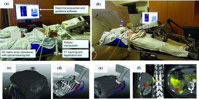
In addition to the robotic manipulator, the US guidance system includes (1) an US scanner, (2) a 3D optical localizer with tracking tools to establish spatial relationships between the US images, patient, and planning CT [Fig. 5(a)], and (3) real-time acquisition and guidance software.
FIG. 5.
(a) Illustration of the robotic-US guidance system and its components deployed during clinical CT simulation of a liver SABR patient. An additional component (not shown) is an infrared camera that tracks the pictured tracking tools. The manipulator is in position for trans-coastal liver imaging. (b) As in (a), with the manipulator in position for transabdominal liver imaging. (c) A CT tracking and registration tool attached to the CT table allows registration of the US probe and US images with the planning CT. (d) A TVM generated from the planning CT guides the placement of the US probe and manipulator toward the location of the target (segmented in red) through imaging positions with available acoustic windows. (e) Live display of the US probe on the patient surface overlaid with the TVM guides placement of the probe. (f) Live 3D US fusion with planning CT and localized lesion provides visual confirmation of the suitability of the current imaging position suggested by the TVM as shown in (d) and (e). Ultrasound image overlay in yellow demonstrates alignment of the liver-lung interface (left image, right side) and reflection from ribs (right image, bottom).
2.B.1. US scanner
Either a Philips iU22 or Philips EPIQ 7 scanner with an X6-1 matrix array transducer (9212 elements, 6-1 MHz, 3.2 MHz central frequency) is used to acquire US volumes. With this transducer, the scanners can provide 4D B-mode US images at a rate varying from 1 to 15 volumes/s, depending on acquisition parameters such as volume field-of-view (maximum of 100° azimuth × 90° elevation), imaging depth, and resolution. Communication between the US scanner and the interventional workstation running the acquisition and guidance software is performed using a Philips digital network link (DNL) protocol.
2.B.2. Optical localizer
An optical camera (Polaris, NDI, Waterloo, ON, Canada) is used to track two tools during CT simulation. The first tool is attached to the X6-1 transducer, allowing real-time registration and fusion of the US volumes and the planning CT after a spatial calibration process.20 The X6-1 tool comprises a pair of tracking markers which increases the range of probe orientations visible to the camera. The second tool—referred to as the CT tracking and registration tool—is attached to the table prior to the CT scan. Once the tool is localized within the CT scan, it links the US images to the CT coordinate space regardless of the current position of the optical camera. With this arrangement, as long as the X6-1 and the CT localization tool remain visible, the camera can be placed anywhere in the room and its position can even be changed during the imaging session as long as the optical tools remain within the operating volume and view of the camera.
2.B.3. Software
The MevisLab platform21 was used for the development of a real-time acquisition and guidance software as well as the virtual environment for simulation/verification of treatments with robotic US guidance. The software was developed using customized MevisLab modules written in c++ and python. The user interface was implemented using MevisLab’s custom mdl language with additional python scripting. The software runs on a dedicated interventional computer workstation and communicates with the US device, robot, tracking system, and existing radiotherapy planning system to provide functions such as TVM calculation prior to US imaging, guidance with target visibility for transducer placement, 4D US acquisition and display, US-CT registration and overlay, as well as simulation and verification of radiation plans involving the robotic imaging hardware. Further details on some of the key aspects of the software are provided in Secs. 2.C and 2.D below.
2.C. Target visibility map computation and evaluation
The computation of the TVM is based on the simulation of US propagation on the basis of an underlying CT model.22,23 Given that our objective is to identify locations on the patient skin that provide acoustic windows toward a CT localized target, a full US image simulation that accounts for reflection (transmission), absorption, and scattering of the US rays is not performed. Instead, only the overall transmission of US rays emanating from a point on the skin toward a rasterized representation of the target is simulated. In brief, an US beam traveling in homogeneous soft tissue transfers a large fraction of its energy into localized heating of the tissues and its intensity decreases following an exponential law [Eq. (1)]:
| (1) |
where μ is the attenuation coefficient and d is the depth to the point of interest. This equation can be rewritten as [Eq. (2)]
| (2) |
to reflect the fact that the attenuation coefficient μ is proportional to the US frequency f in the diagnostic range. The value of α ranges from 0.5 to 1.2 (dB/cm)/MHz (Ref. 24) for soft tissue. When traversing areas with differing acoustic impedances Z1 and Z1 in a piecewise homogeneous medium with wave incidence perpendicular to the interface, the US beam is partially reflected and the intensity of the transmitted beam is given by [Eq. (3)]
| (3) |
where I1 is the intensity of the incident beam, I2 is the intensity of the transmitted beam, and the acoustic impedance Z = ρc, where ρ is the density of the medium and c is the sound velocity in the medium.
Based on this simplified model, the TVM is simulated from the planning CT as follows. First, CT numbers are converted to density values through prior calibration with known tissue mimicking materials. For soft tissue, the resulting density values are mapped onto acoustic impedances using the relationship Z = ρc with the approximation of constant velocity c ≅ 1540 m/s in soft tissue. Given that the velocity of sound is substantially different in bone and air than in soft tissue, areas of lung, bone, and gastrointestinal air pockets need to be treated differently. One approach is to segment these regions and then assign the respective sound velocities, acoustic impedances, and attenuation coefficients. Instead, here a conservative approach is adopted that forces these areas to be interpreted as acoustic barriers during the visibility map calculation. To achieve this, first areas of bone, lungs, and air pockets are segmented with a region growing algorithm. Next, morphological dilation of the segmented binary volumes is performed to create additional margins, and finally unrealistically high attenuation coefficients are assigned to the segmented and expanded regions, which forces these regions to act as acoustic barriers.
After the mapping of CT numbers to acoustic parameters, US transmission values are calculated for every sampled point within the target from each sampled point on the skin surface along the surface-to-target point direction. The calculation accounts for the US beam attenuation within voxels along the US ray as well as US beam reflection across voxel boundaries. The minimum transmission value for all target points is then assigned to the current surface point to indicate the visibility of the target from this point. The minimum transmission value is selected as the most conservative approach as it requires that an adequate acoustic window exist for every single target point. This calculation is then repeated for all points sampled on the skin surface. The extent of the sampled region is limited to within 25 cm from the target since this roughly corresponds to the maximum penetration depth for modern US scanners at 2 MHz imaging frequency and 110 dB dynamic range.25 After the map computation, we only visualize map locations for which the total attenuation is smaller than 75 dB which are interpreted as locations sufficient for target imaging.
Computation of the TVM is a computationally expensive task. An Nvidia Fermi graphics card and the Compute Unified Device Architecture (CUDA) parallel computation technology are used to accelerate the calculation.22 For the investigated clinical cases, the calculation time is about 20–40 s depending on CT resolution, target size, and skin surface/target spatial sampling density.
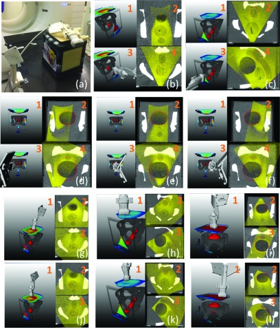
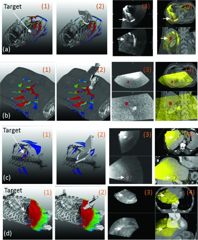
The fidelity of the TVM was evaluated both in patients and in a CIRS multimodality pelvic phantom (Norfolk, VA, USA) [Fig. 6(a)]. After a CT scan, approximate prostate, bladder, and rectum targets were outlined in the phantom and the corresponding TVMs were generated. Then the US probe was placed in some of the suggested imaging positions to acquire 3D US images and visually verify whether such positions indeed present acoustic windows for imaging [Figs. 6(b)–6(l)]. In patients, the process was analogous with imaging targets outlined by physicians at the location of the liver lesion to be treated (Fig. 7).
FIG. 6.
TVM evaluation in a phantom. (a) Phantom and experimental setup. [(b)–(f)]1: Volume rendering showing an outlined target (red), bone, and color coded TVM. Regions encompassing prostate, rectum, and bladder were outlined as targets on CT. 3. As in 1 with US probe in a recorded imaging position. 2 and 4. US volume fused with the phantom CT. The US volume is acquired with the US probe in the imaging position depicted in 2. [(g)–(l)]1: Volume rendering showing an outlined target (red), bone, color coded TVM, and US probe in recorded imaging position. 2 and 3. US volume fused with the phantom CT. The US volume is acquired with the US probe in the imaging position depicted in 1.
FIG. 7.
[(a)–(d)]. TVM evaluation in three patients, (a) and (b) correspond to two different imaging positions in the same patient. 1. Volume rendering showing an outlined target (red), bone or skin, and color coded TVM. 2. As in 1 with US probe in an imaging position. 3. Orthogonal planes through the US volume acquired with the US probe in the imaging position depicted in 2 (imaging target in red). 4. Hardware fusion of the US volume depicted in 3 with the simulation CT (imaging target in red). White arrows indicate locations of the segmented targets. Note that a skin rendering (rather bone) is shown in (b) as the acoustic barrier was caused by the presence of abdominal gas.
2.D. Virtual environment for simulation and verification of radiation treatments with robotic US guidance
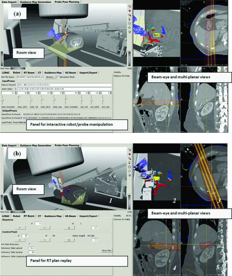
The guidance system includes a virtual environment for simulation and verification of radiation treatments with robotic US imaging (Fig. 4). As shown in Fig. 4, the virtual environment includes computer models for all entities involved in the US-guided radiation delivery: (1) virtual patient, including the planning CT and tumor segmentation; (2) robot, including geometries and kinematics of individual robot links; (3) LINAC, including geometries and kinematics of the gantry, multi-leaf collimator (MLC), table, radiation beam, and isocenter; (4) the US probe, the TVM, and the imaging cone of the US beam; and (5) geometries of the tracking markers and location of the camera. In addition, controls are provided for interactive planning of robot joints [Fig. 4(a)], LINAC axes, and replay of treatment plans [Fig. 4(b)].
FIG. 4.
Virtual environment for simulation and verification of radiation treatments with robotic US guidance. The environment combines all objects involved in the simulation and treatment process: patient CT, segmented structures (DICOM RT structures), radiation beams (DICOM RT plan), delivery system, imaging robot, TVM, and a reference probe (in blue). These objects are rendered in a room view for detection of mechanical interferences as well as combined beam-eye and multiplanar views for detection of entry interference with treatment beams. (a) Panel for robot/probe interactive manipulation and visualization. This panel facilitates placing the probe held by the robot in an imaging pose that reproduces the one used during simulation imaging as captured and represented by the reference probe (in blue). (b) Once the robot is in position, replay of an intended RT plan allows for verification of interferences between the RT plan and robotic imaging hardware. (See color online version.)
During treatment planning, within this environment a planner can direct the robot toward an imaging configuration that reproduces a recorded reference transducer pose used for US imaging during simulation [Fig. 4(a), transducer in blue represents a recorded reference pose used for clinical imaging during simulation]. Once the robot is in an imaging position that matches a recorded reference [Fig. 4(b)], a candidate clinical treatment plan is simulated (replayed) to allow inspections for potential mechanical collisions [Fig. 4(b), room view with user selectable camera point] and/or interferences of the robotic manipulator with the treatment beam [Fig. 4(b), beam-eye and multiplanar views]. If interferences are detected, the system allows identification of the corresponding beam configurations so that they can be eliminated from the treatment plan, in which case additional treatment plan optimization and subsequent verification need to be performed.
The same virtual environment is further intended to be used for final verification immediately before treatment delivery. Once a patient is set-up within the treatment room according to a radiation plan, the previously saved robot configuration and optically tracked probe position are retrieved and used to help place the robot in imaging position. If minor adjustments in probe position and robot configuration are needed for optimizing US image quality, the system updates the robot model configuration and interferences are reverified as described above to confirm lack of interference with the plan to be delivered. We consider the pre-delivery verification to be a mandatory step in the treatment process as slight variations in the robot position with regard to the linear accelerator and patient are to be expected.
2.E. Estimation of the proportion of liver SABR patients amenable to robotic US image guidance of VMAT delivery
The results with regard to the TVM evaluation (Sec. 3.B) suggest that the TVM provides adequate identification of imaging positions with acoustic windows toward a CT-defined target. Based on this observation, the virtual simulation environment was used to evaluate the proportion of liver SABR patients amenable to robotic US image guidance of VMAT delivery. The influence of robotic US imaging hardware on the existing treatment plan was evaluated using 20 VMAT treatment plans from liver SABR patients. For each case, the CT and treatment plan were loaded into the virtual simulation environment (Fig. 4) and the TVMs were generated for both PTV and GTV. Then for each of the PTVs and GTVs, using the TVM for guidance and by virtually manipulating robot joints and navigating through the planned treatment beams, at least one optimal imaging position was searched for that satisfying all of the following requirements:
-
•
no entrance interference between the imaging hardware (specifically the US probe, tracking markers, and robot wrist/arm) and all planned radiation beams;
-
•
no mechanical collision/interference between the imaging hardware and the LINAC (specifically the gantry and table) or LINAC and patient;
-
•
the US imaging direction is aligned roughly orthogonal to axis 6 of the robot (Fig. 5) so that the robotic force control would maintain sufficient contact with the patient surface;
-
•
the target must be within the field of view of the US beam;
-
•
the angle between the imaging direction and the normal of the body surface does not exceed 20°–25°;
-
•
the area of the identified TVM window should be comparable to the footprint the US probe small; and
-
•
the tracking markers on the probe must be visible to the camera.
If such imaging positions were found, the patient case was deemed to be amenable to robotic US imaging without modifying the existing treatment plan. When such a position was not found, the requirements were relaxed by allowing interference between the imaging hardware and a treatment beam. With relaxed requirements, an US imaging location was searched for that satisfied all of the requirements listed above except the first one.
3. RESULTS
3.A. Clinical imaging
The robotic 4D US guidance system was deployed in IRB-approved imaging sessions during the initial CT simulation of two liver SABR patients. Figure 5 depicts various hardware and software components of the clinically deployed system and workflow, with further images used in the TVM evaluation shown in Fig. 7. US acquisition rates were 3–4 volumes/s and US images were acquired autonomously by the robot for 50–240 second sessions.
Figures 5(a) and 5(b) provide photographs of the clinical setup in trans-coastal and transabdominal US liver imaging positions, respectively. Prior to the planning CT scan, the base frame of the robot (Sec. 2.A) was mounted on the table top between the legs of the patient and an optical CT registration tool was attached on the side of the table in the vicinity of the scanned region. After the CT scan, the CT registration tool was localized within the CT image [Fig. 5(c)] so that the optically tracked US probe and US images could be displayed within the CT coordinate space. Based on a therapy target designated within the CT scan by the treating physician (Figs. 5(d) and 5(f), in red), the system software generated a TVM [Figs. 5(d) and 5(e)] which depicted areas on the patient skin with acoustic windows to the target (Sec. 2.C). The robot was next mounted on the base frame, and real-time acquisition and guidance software synchronously visualized an US probe model on the top of the CT and TVM to guide the robot and probe positioning. Upon confirmation of the suitability of a given US probe position for imaging [Fig. 5(f)], the robot autonomously maintained the US probe imaging position and pressure. During US imaging, live display of all hardware [Fig. 5(e)] and images was provided [Fig. 5(f)] and recorded for the purposes of treatment planning.
For the same patient, Fig. 7(a1) demonstrates the recorded probe position for another trans-coastal imaging configuration realized with the robotic manipulator. The corresponding US images and their fusion with the planning CT are shown in Figs. 7(a3) and 7(a4), respectively. For the second patient, a trans-coastal imaging configuration realized with the robot is shown in Fig. 7(c3). The corresponding US images and their fusion with the planning CT are shown in Figs. 7(c3) and 7(c4), respectively.
3.B. Target visibility map evaluation
Figures 6(b)–6(l) illustrate 11 imaging positions on three separate TVMs generated for three phantom targets (prostate, rectum, and bladder). The overlays of the US images acquired at these positions [Figs. 6(b2,b4)–6(f2,f4) and 6(g2,g3)–6(l2,l3)] with CT and target (in red) demonstrate that US imaging of nonobstructed targets was indeed possible at these positions. Furthermore, our implementation correctly captured the following essential aspects of US imaging:
-
•
Bone presents an acoustic barrier. This was correctly reflected by the triangularly shaped transperineal (phan-tom-side) TVM windows for the prostate [Fig. 6(b1)] and rectum [Fig. 6(c1)]. For the bladder, three phantom-side TVM windows were correctly indicated [Figs. 6(d1)–6(f1)], but these TVM windows were of much smaller size because of the larger bladder volume.
-
•
Smaller imaging depths are preferred because of lower attenuation. This was correctly reflected for all targets. For the bladder the small TVM phantom-side windows had lower visibility values [Figs. 6(d1)–6(f1)] compared to the large anterior (phantom top) TVM window [Figs. 6(i1) and 6(l1)]. As expected, for the prostate and the rectum the reverse was indicated on the TVMs [Figs. 6(g1) and 6(h1)].
The TVM also captured some more subtle features of the imaging geometry. For instance, the heterogeneous map distribution on top of the phantom in Fig. 6(g1) correctly reflected the fact that some areas on the anterior surface are preferable for prostate imaging since for these the bladder was between the probe and the prostate thus lowering the US beam attenuation. Similarly, the gradient of the TVM in the triangular transperineal rectum imaging window, Fig. 6(c1), reflects the decreasing depth of the rectum toward the anterior tip of the window.
Figure 6 also demonstrates that in some cases the targets were not entirely encompassed by the US field of view which occurred for two reasons. The first is that the digital navigation link on the iU22 US scanner does not support the transmission of very large datasets, effectively limiting the US field of view to about 55° in the axial and elevational direction as shown in Fig. 6(i1). This has been subsequently resolved on the EPIQ 7 platform. The second is that for some of the phantom-side imaging positions [Figs. 6(d)–6(f)] it was impossible to center the probe on the imaging window suggested by the TVM. For instance, for the cases shown in Figs. 6(d) and 6(f), the sidewall of the phantom prevented the probe being centered on the respective imaging windows. For the transperineal bladder imaging, the suggested imaging window [Fig. 6(e)] was quite posterior and the probe could not be placed that low because of the interference of the optical tracking tool with the CT table top. At the same time, the fact that significant volumes of the targets were still captured even though the US probe was not centered exactly within the suggested imaging windows indicates that our conservatively generated TVM is quite robust in providing probe placement guidance.
Figure 7 illustrates similar results from our evaluation of the TVM in patients. For the patient case presented in Figs. 5, 7(a1,a2) shows placement of the robotically manipulated US probe in a trans-coastal imaging position suggested by the TVM. [Note that the position is different from the one shown in Figs. 5(a) and 5(d).] Figure 7(a3,a4) illustrates that indeed US imaging for this position was possible. Figure 7(a3,a4) further illustrates a rib shadowing effect which was to be expected as the sonographer did not align the face of the probe with the window indicated by the probe placement map [Fig. 7(a1,a2)].
For the same patient, Fig. 7(b1,b2) illustrates that for certain areas on the abdomen imaging of the target was not possible because of gas present. This was confirmed by the lack of anatomical information acquired with the probe at this location [Fig. 7(b3,b4)].
Figure 7(c1,c2) presents another example from a robotically imaged patient with large body mass index. As expected, compared to the other two patients [Figs. 7(a) and 7(d)] the TVM had significantly lower values which was also reflected in the lower quality US images which nevertheless allowed the visualization and monitoring of a large vessel in the immediate vicinity of the target [Fig. 7(c3)] as it can be confirmed through the overlay of the 3D US image with the corresponding CT. Note that the last example [presented in Fig. 7(d)] is from a free-hand US acquisition performed on a third patient under a separate IRB-approved clinical study.
3.C. Estimation of the proportion of liver SABR patients amenable to robotic US image guidance of VMAT delivery
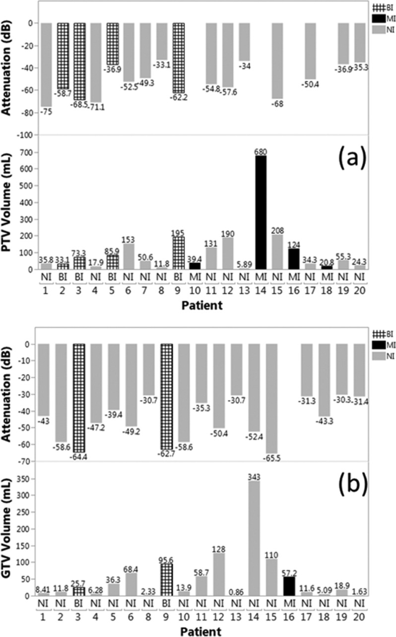
For all 20 retrospective patients, Fig. 8(a) shows PTV volume, PTV visibility value, and robotic placement interference status when the robotic US hardware was virtually placed in optimal configuration within the virtual simulation environment (Sec. 2.D) according to the criteria described in Sec. 2.E. Figure 9 illustrates the PTV shapes and their locations within the liver. For the studied population of patients, the mean PTV volume was 108.5 ± 149.5 ml. The mean PTV visibility according to the TVM was −53.7 ± 14 dB. In 12 cases the planned imaging position was not interfering (NI), in four cases the imaging position led to beam interference (BI) with the imaging hardware, and in four cases the imaging position could not be found because of mechanical interference (MI). MI is defined as physical interference between the robot or US probe and the LINAC, or lack of a sufficient acoustic window as determined by the −75 dB TVM threshold.
FIG. 8.
(a) PTV volume, PTV visibility, and robotic placement interference status for individual patients with the PTV as the imaging target. NI: no interference; BI: beam interference with entering beam; MI: mechanical interference—physical collision threat or lack of a sufficient acoustic window. (b) As in (a) with the GTV as the imaging target. Note that for patient 7, GTV values are missing as the GTV was not outlined for treatment planning.
FIG. 9.
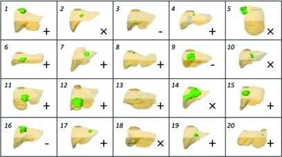
PTV (green) shape and location with respect to liver (brown), coronal view, for all patient cases. Legend: (+) noninterfering US guidance possible with PTV, (×) noninterfering US guidance not possible with PTV but possible with GTV, (-) noninterfering US guidance not possible with GTV.
Figure 8(b) presents the same data as Fig. 8(a) for the respective GTVs. The mean GTV volume was 52.9 ± 80.6 ml. The mean GTV visibility according to the TVM was −45.8 ± 12.6 dB. In 17 cases the planned imaging position was NI, in two cases the imaging position led to BI with the imaging hardware, and in one case the imaging position could not be found because of MI.
In summary, for PTV targets, we estimate that robotic US guidance without mechanical collision (i.e., allowing only interference with treatment beams) would be possible in 80% of the cases and guidance without beam interference would be possible in 60% of the cases. For the smaller GTV targets, these proportions would be 95% and 85% correspondingly. For the three cases where noninterfering guidance would not be possible target size, elongated shape, and depth were the main factors limiting the availability of noninterfering imaging positions (Fig. 9).
4. DISCUSSION AND CONCLUSIONS
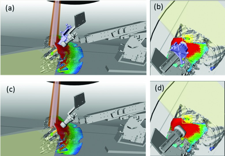
In this paper we present the current iteration of our robotic US guidance system and the first examples of clinical imaging with the system in the setting of CT simulation of liver SABR patients. The clinical imaging is performed within an IRB-approved pilot study aiming at evaluating the performance of the system in patients and identifying challenges and respective solutions prior to deploying the system for real-time 3D soft-tissue imaging during treatment. The most significant findings are that (1) unattended robotic clinical imaging is possible even for challenging trans-coastal positions; (2) TVMs can guide the US probe placement toward imaging positions with acoustic windows toward the target; (3) intrafractional US may be an option for 85%–95% of the liver SABR cases. At the same time, we have identified several potential venues for improvement. For instance, some enhancements are necessary to guide toward the selection of imaging positions that while maintaining TVM acoustic window with low attenuation also provide maximum separation between the target and standard coplanar beam arrangements. An example shown in Fig. 10 illustrates that for this particular patient, the imaging position used during simulation was deemed sufficiently far from a potential coplanar VMAT trajectory. However, a subsequent evaluation with the actual VMAT treatment plan within the system simulation and verification environment exposed some marginal interference [Fig. 10(b)] with the actual treatment plan. A large area on the TVM was available inferiorly which would not be interfering with the plan [Figs. 10(c) and 10(d)], but these inferior positions were not attempted during the simulation session.
FIG. 10.
(a) Actual (in blue) and possible (in gray) imaging position. (b) Beam-eye view demonstrates that the actual position visually deemed noninterfering during simulation interferes with a beam from the VMAT SABR plan. [(c) and (d)] Placing the probe further inferiorly avoids beam interference.
Another potential venue for improvement is revealed by our simulation study which indicates that in about 85% of the cases, imaging and tracking of sufficiently small targets (GTVs) may be possible without changing existing plans. Thus in a workflow that does not involve CT scanning of the robotic manipulator with a dummy probe, some of the design constraints can be removed. For instance, plastic parts in the robotic manipulator wrist could be replaced by light and sturdy metal parts, further decreasing the robot footprint and increasing ruggedness. Position encoders could be placed in the immediate vicinity of the mechanical axes, thus reducing complexity of the cable system and improving the accuracy of mechanically encoded axis positions. This could eliminate the need for optical tracking, with potential benefits such as a further decrease in the proportion of cases with mechanical and beam interferences, accommodation of more complex non-coplanar beam arrangements if necessary, as well as lower system cost. Some of these prospective improvements are currently under investigation.
ACKNOWLEDGMENT
This work is supported by NIH Grant No. R41CA174089.
CONFLICT OF INTEREST DISCLOSURE
Dimitre Hristov and Jeffrey Schlosser are shareholders of SoniTrack Systems, Inc.
REFERENCES
- 1.Van De Voorde L., Vanneste B., Houben R., Damen P., van den Bogaard J., Lammering G., Dejong K., de Vos-Geelen J., Buijsen J., Ollers M., Berbee M., and Lambin P., “Image-guided stereotactic ablative radiotherapy for the liver: A safe and effective treatment,” Eur. J. Surg. Oncol. , 249–256 (2015). 10.1016/j.ejso.2014.10.053 [DOI] [PubMed] [Google Scholar]
- 2.Taguchi H., Sakuhara Y., Hige S., Kitamura K., Osaka Y., Abo D., Uchida D., Sawada A., Kamiyama T., Shimizu T., Shirato H., and Miyasaka K., “Intercepting radiotherapy using a real-time tumor-tracking radiotherapy system for highly selected patients with hepatocellular carcinoma unresectable with other modalities,” Int. J. Radiat. Oncol., Biol., Phys. , 376–380 (2007). 10.1016/j.ijrobp.2007.03.042 [DOI] [PubMed] [Google Scholar]
- 3.Van den Begin R., Engels B., Gevaert T., Duchateau M., Tournel K., Verellen D., Storme G., and De Ridder M., “Impact of inadequate respiratory motion management in SBRT for oligometastatic colorectal cancer,” Radiother. Oncol. , 235–239 (2014). 10.1016/j.radonc.2014.11.005 [DOI] [PubMed] [Google Scholar]
- 4.Eccles C. L., Patel R., Simeonov A. K., Lockwood G., Haider M., and Dawson L. A., “Comparison of liver tumor motion with and without abdominal compression using cine-magnetic resonance imaging,” Int. J. Radiat. Oncol., Biol., Phys. , 602–608 (2011). 10.1016/j.ijrobp.2010.04.028 [DOI] [PubMed] [Google Scholar]
- 5.Poulsen P. R., Worm E. S., Hansen R., Larsen L. P., Grau C., and Hoyer M., “Respiratory gating based on internal electromagnetic motion monitoring during stereotactic liver radiation therapy: First results,” Acta Oncol. , 1445–1452 (2015). 10.3109/0284186x.2015.1062134 [DOI] [PubMed] [Google Scholar]
- 6.Schweikard A., Shiomi H., and Adler J., “Respiration tracking in radiosurgery,” Med. Phys. , 2738–2741 (2004). 10.1118/1.1774132 [DOI] [PubMed] [Google Scholar]
- 7.Habermehl D., Naumann P., Bendl R., Oelfke U., Nill S., Debus J., and Combs S. E., “Evaluation of inter- and intrafractional motion of liver tumors using interstitial markers and implantable electromagnetic radiotransmitters in the context of image-guided radiotherapy (IGRT)—The ESMERALDA trial,” Radiat. Oncol. , 143 (2015). 10.1186/s13014-015-0456-y [DOI] [PMC free article] [PubMed] [Google Scholar]
- 8.Poulsen P. R., Worm E. S., Petersen J. B., Grau C., Fledelius W., and Hoyer M., “Kilovoltage intrafraction motion monitoring and target dose reconstruction for stereotactic volumetric modulated arc therapy of tumors in the liver,” Radiother. Oncol. , 424–430 (2014). 10.1016/j.radonc.2014.05.007 [DOI] [PubMed] [Google Scholar]
- 9.Worm E. S., Hoyer M., Fledelius W., and Poulsen P. R., “Three-dimensional, time-resolved, intrafraction motion monitoring throughout stereotactic liver radiation therapy on a conventional linear accelerator,” Int. J. Radiat. Oncol., Biol., Phys. , 190–197 (2013). 10.1016/j.ijrobp.2012.12.017 [DOI] [PubMed] [Google Scholar]
- 10.Kitamura K., Shirato H., Seppenwoolde Y., Shimizu T., Kodama Y., Endo H., Onimaru R., Oda M., Fujita K., Shimizu S., and Miyasaka K., “Tumor location, cirrhosis, and surgical history contribute to tumor movement in the liver, as measured during stereotactic irradiation using a real-time tumor-tracking radiotherapy system,” Int. J. Radiat. Oncol., Biol., Phys. , 221–228 (2003). 10.1016/S0360-3016(03)00082-8 [DOI] [PubMed] [Google Scholar]
- 11.Seppenwoolde Y., Wunderink W., Wunderink-van Veen S. R., Storchi P., Mendez Romero A., and Heijmen B. J., “Treatment precision of image-guided liver SBRT using implanted fiducial markers depends on marker-tumour distance,” Phys. Med. Biol. , 5445–5468 (2011). 10.1088/0031-9155/56/17/001 [DOI] [PubMed] [Google Scholar]
- 12.Wunderink W., Mendez Romero A., Seppenwoolde Y., de Boer H., Levendag P., and Heijmen B., “Potentials and limitations of guiding liver stereotactic body radiation therapy set-up on liver-implanted fiducial markers,” Int. J. Radiat. Oncol., Biol., Phys. , 1573–1583 (2010). 10.1016/j.ijrobp.2009.10.040 [DOI] [PubMed] [Google Scholar]
- 13.Schlosser J., Salisbury K., and Hristov D., “Telerobotic system concept for real-time soft-tissue imaging during radiotherapy beam delivery,” Med. Phys. , 6357–6367 (2010). 10.1118/1.3515457 [DOI] [PubMed] [Google Scholar]
- 14.Schlosser J., Salisbury K., and Hristov D., “Online image-based monitoring of soft-tissue displacements for radiation therapy of the prostate,” Int. J. Radiat. Oncol., Biol., Phys. , 1633–1640 (2012). 10.1016/j.ijrobp.2011.10.049 [DOI] [PubMed] [Google Scholar]
- 15.Bazalova-Carter M., Schlosser J., Chen J., and Hristov D., “Monte Carlo modeling of ultrasound probes for image guided radiotherapy,” Med. Phys. , 5745–5756 (2015). 10.1118/1.4929978 [DOI] [PMC free article] [PubMed] [Google Scholar]
- 16.Wu J., Dandekar O., Nazareth D., Lei P., D’Souza W., and Shekhar R., “Effect of ultrasound probe on dose delivery during real-time ultrasound-guided tumor tracking,” Conf. Proc. IEEE Eng. Med. Biol. Soc. , 3799–3802 (2006). 10.1109/iembs.2006.4398277 [DOI] [PubMed] [Google Scholar]
- 17.Zhong Y., Stephans K., Qi P., Yu N., Wong J., and Xia P., “Assessing feasibility of real-time ultrasound monitoring in stereotactic body radiotherapy of liver tumors,” Technol. Cancer Res. Treat. , 243–250 (2013). 10.7785/tcrt.2012.500323 [DOI] [PubMed] [Google Scholar]
- 18.Lediju Bell M. A., Sen H. T., Iordachita I., Kazanzides P., and Wong J., “In vivo reproducibility of robotic probe placement for a novel ultrasound-guided radiation therapy system,” J. Med. Imaging , 025001 (2014). 10.1117/1.jmi.1.2.025001 [DOI] [PMC free article] [PubMed] [Google Scholar]
- 19.Schlosser J. and Hristov D., “Radiolucent 4D ultrasound imaging: System design and application to radiotherapy guidance,” IEEE Trans. Med. Imaging (10), 2292–2300 (2016). 10.1109/tmi.2016.2559499 [DOI] [PubMed] [Google Scholar]
- 20.Schlosser J., Kirmizibayrak C., Shamdasani V., Metz S., and Hristov D., “Automatic 3D ultrasound calibration for image guided therapy using intramodality image registration,” Phys. Med. Biol. , 7481–7496 (2013). 10.1088/0031-9155/58/21/7481 [DOI] [PMC free article] [PubMed] [Google Scholar]
- 21.Heckel F., Schwier M., and Peitgen H. O., “Object-oriented application development with MeVisLab and Python informatik,” in Im Focus das Leben(Beiträge der 39. Jahrestagung der Gesellschaft für Informatik e.V.,Lubeck, Germany, 2009) pp. 1338–1351. [Google Scholar]
- 22.Reichl T., Passenger J., Acosta O., and Salvado O., “Ultrasound goes GPU: Real-time simulation using CUDA,” Proc. SPIE , 726116 (2009). 10.1117/12.812486 [DOI] [Google Scholar]
- 23.Kutter O., Shams R., and Navab N., “Visualization and GPU-accelerated simulation of medical ultrasound from CT images,” Comput. Methods Programs Biomed. , 250–266 (2009). 10.1016/j.cmpb.2008.12.011 [DOI] [PubMed] [Google Scholar]
- 24.Mast T. D., “Empirical relationships between acoustic parameters in human soft tissues,” Acoust. Res. Lett. Online , 37–42 (2000). 10.1121/1.1336896 [DOI] [Google Scholar]
- 25.Oppelt A., “Physical principles of medical ultrasound,” in Imaging Systems for Medical Diagnostics: Fundamentals, Technical Solutions and Applications for Systems Applying Ionizing Radiation, Nuclear Magnetic Resonance and Ultrasound, edited byOppelt A. (Publicis Corporate Publishing, Erlangen, Germany, 2006), pp. 184–212. [Google Scholar]


