

A pacemaker is a device that provides electrical stimuli to maintain or restore a normal heartbeat. Pacing systems are made of 2 implantable cardiac components (the pacemaker pulse generator and the intracardiac leads), and can be interrogated by using a wireless, telemetered, external programming device.1 Pacemakers can be dual- or single-chamber. Single-chamber pacemakers have a single lead, which is placed either into the right atrium or, more often, into the right ventricle. Dual-chamber pacemakers have 2 leads, with one in the right atrium and the other in the right ventricle.2
Causes of Pacemaker Malfunction
Patients with pacemakers generally face problems that can be grouped into the following categories3:
- 1) Failure to pace the appropriate cardiac chamber:
- Output failure
- Capture failure
- 2) Problem with detecting intracardiac signals:
- Undersensing
- Oversensing
- 3) Pseudomalfunction:
- Crosstalk with resultant safety pacing
- Pacemaker-mediated tachycardia
- Sensor-induced tachycardia
- Runaway pacemaker
- Lead-displacement dysrhythmia
- Twiddler syndrome
Output Failure
A failure of output is suspected if the heart rate is below the programmed lower rate of the pacemaker and no pacer electrical output is noted on the electrocardiogram (ECG)—that is, pacing spikes are absent. Causes of output failure are generally lead failure (lead fracture, lead displacement), generator failure, battery failure, crosstalk inhibition, or oversensing (Fig. 1).4
Fig. 1.
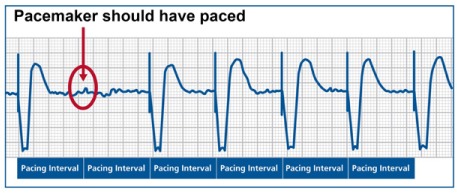
Output failure. Surface electrocardiogram from a patient with a single-chamber pacemaker shows underlying atrial fibrillation and ventricular pacing at a rate of 70 beats/min. There is no pacing spike at the expected interval at the beginning of the tracing (circle), which suggests a failure of pacing output from the pacemaker. At the bottom of the tracing, the expected pacing intervals are marked.
Capture Failure
Capture failure occurs when the generated pacing stimulus does not initiate myocardial depolarization. On the surface ECG, pacing spikes are present, but they are not followed by a QRS complex in the event of ventricular noncapture or by the lack of P waves in the event of atrial noncapture (Fig. 2). The main causes of this failure are lead dislodgment, low output, lead maturation, and lead or pacer failure (fibrosis, fracture, low pacing voltage, or elevated myocardial pacing thresholds).5
Fig. 2.
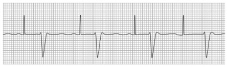
Ventricular noncapture. Surface electrocardiogram from a patient with a single-chamber pacemaker shows sinus rhythm with first-degree atrioventricular block. Pacing spikes are visible at a rate of 65 beats/min and are marching through without capture, even though the ventricular myocardium is not expected to be refractory at those times.
What Affects the Pacing Threshold?
The pacing threshold is the minimum required energy that consistently triggers a depolarization of the paced chamber. Multiple factors—including antiarrhythmic drug use, physical activity level, posture, time of day, and comorbidity—could all affect the pacing threshold.6
Undersensing
Undersensing occurs when the pacemaker fails to detect spontaneous myocardial depolarization, which results in asynchronous pacing. Atrial or ventricular pacing spikes arise regardless of P waves or QRS complex. This typically results in the appearance of too many pacing spikes, as seen on ECG (Fig. 3). The main causes of undersensing are pacemaker programming problems (improper sensing threshold), insufficient myocardial voltage signal, lead or pacer failure (fibrosis, fracture, etc.), or an electrolyte abnormality.7
Fig. 3.
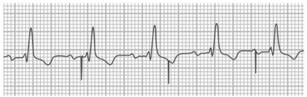
Ventricular undersensing. Surface electrocardiogram shows sinus rhythm with first-degree atrioventricular block and bundle branch block in a patient with a pacemaker. Ventricular pacing spikes are visible and not only fail to capture the myocardium but show evidence of undersensing: note the inappropriate pacing soon after a QRS complex, after the 3rd beat.
Oversensing
Oversensing occurs when the pacemaker senses electrical signals that it should not normally encounter, which results in inappropriate inhibition of the pacing stimulus. In addition to the native cardiac depolarization signals (P or R waves), any electrical signal with sufficient amplitude and frequent occurrence can be sensed and can inhibit the pacemaker when pacing is needed. Oversensing can be caused by physiologic signals like T waves or by myopotential (and nonphysiologic) signals like electromagnetic interference or a lead failure (an insulation break or a lead fracture) (Fig. 4).7
Fig. 4.
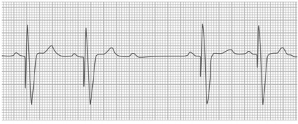
Ventricular oversensing. Surface electrocardiogram shows sinus rhythm with ventricular pacing. After the 3rd sinus P wave, the pacing spike is absent—which suggests oversensing by the pacemaker, with inappropriate inhibition of pacing and an asystolic pause in a pacemaker-dependent patient.
Ventricular Fusion and Pseudofusion
“Ventricular fusion” is the electrical summation of a heart's intrinsic beat and a depolarization from a pacing stimulus. The hallmark of this phenomenon is that its morphology lies between a fully paced beat and a complete intrinsic beat. On the other hand, when the pacemaker spikes fall directly on top of an intrinsic beat, without contributing to the actual depolarization, this event is called “pseudofusion” beat.7 Fusion and pseudofusion beats are both consistent with normal pacemaker behavior (Fig. 5).
Fig. 5.
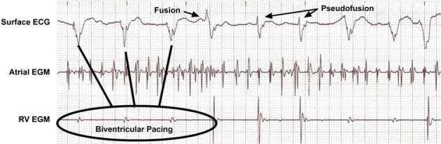
Ventricular fusion and pseudofusion. Intracardiac atrial and right ventricular (RV) electrograms (EGMs), along with a surface electrocardiogram (ECG), in a patient with atrial fibrillation and congestive heart failure. The patient is being treated with cardiac resynchronization therapy, and the tracing shows QRS complexes of various morphologies and durations. Some resemble intrinsic QRS and represent pseudofusion, whereas others show a morphology between intrinsic beats and paced beats and thereby represent true fusion between conducted impulses and paced beats.
Pseudomalfunction
Pseudomalfunctions are unusual and unexpected ECG findings that appear to be pacemaker malfunctions but actually are normal pacemaker behavior. Pseudomalfunctions are classified under 3 categories: 1) rate-related, 2) atrioventricular (AV) interval/refractory period-related, and 3) model-related.
Most common are the rate-related pseudomalfunctions. Rate changes in the presence of normal pacemaker function can occur because of magnet operation, timing variations (A-A vs V-V), upper-rate behavior (Wenckebach or 2:1 block), pacemaker-mediated tachycardia (PMT), or rate response.7
The following paragraphs cover some of the typical clinical situations presenting as pseudomalfunctions.
Ventricular Safety Pacing. Ventricular safety pacing (SP) prevents ventricular asystole due to crosstalk. Pacemaker crosstalk in a dual-chamber pacemaker refers to the detection of a paced signal in one chamber by the lead in another chamber, and to the misrepresentation of the paced signal as a cardiac depolarization signal. This, in turn, results in inappropriate inhibition of pacing in the 2nd chamber.8
Ventricular safety pacing delivers a ventricular pacing stimulus after detecting a ventricular “sense event” shortly after an atrial paced event (SP algorithms differ among pacemaker manufacturers).9 Ventricular safety pacing typically results in the appearance of 2 very closely spaced atrial and ventricular paced events on ECG (Fig. 6).
Fig. 6.

Surface electrocardiogram (ECG) with intracardiac atrial and ventricular electrograms (EGMs). This is an example of crosstalk wherein the pacing signal from one channel (in this case, the atrium) is sensed on the other channel (in this case, the ventricle). In this example, the cross-sensed signal is ignored and no action is taken by the pacemaker. In other situations, the cross-sensed signal can be misconstrued as a pacemaker malfunction and can trigger ventricular safety pacing.
Pacemaker-Mediated Tachycardia. Pacemaker-mediated tachycardia is an endless-loop tachycardia, sustained, in part, by the presence of the pacemaker. Pacemaker-mediated tachycardia requires the presence of retrograde ventriculoatrial conduction and a triggering event like premature ventricular contraction or loss of AV synchrony. Pacemaker-mediated tachycardia is similar to a re-entrant tachycardia, except that the pacemaker forms part of the re-entrant circuit; the tachycardia could therefore be avoided by programming a sufficiently long postventricular atrial refractory period (PVARP).10 Placing a magnet on the device during the PMT will change the pacemaker's mode to dual-chamber pacing mode (in DOO, intrinsic P waves and R waves are ignored), which results in the termination of tachycardia by suspending the pacemaker's sensing function (Fig. 7).4,10
Fig. 7.
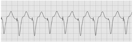
Surface electrocardiogram shows an example of pacemaker-mediated tachycardia. Ventricular pacing spikes are visible at a rate of 120 beats/min, along with appropriate capture. Pacemaker is pacing at the upper rate as it tracks the retrogradely conducted P waves in this dual-chamber pacemaker.
Upper-Rate Behavior. Upper-rate behavior refers to the pacing characteristics seen in dual-chambered pacemakers programmed to an atrial tracking mode as the atrial rate increases and approaches a certain upper threshold. In dual-chambered devices, it is necessary to limit the rate at which the ventricle can pace in the presence of high atrial rates. This limit is called the maximum tracking rate (MTR) and is a programmable value. The upper-rate behavior depends upon MTR and total atrial refractory period (TARP). The TARP is equal to AV delay + PVARP. When the atrial rate exceeds MTR, it results in pacemaker Wenckebach. If the atrial rate keeps increasing and exceeds the TARP, it will result in pacemaker 2:1 AV block.3
Footnotes
★ CME Credit
Presented at the 17th Symposium on Cardiac Arrhythmias in Honor of Dr. Ali Massumi, Houston, 20 February 2016.
Section Editor: Mohammad Saeed, MD
From: Department of Cardiology (Drs. Saeed and Safavi-Naeini), Texas Heart Institute; and Section of Cardiology, Department of Medicine (Dr. Saeed), Baylor College of Medicine; Houston, Texas 77030
References
- 1.Buch E, Boyle NG, Belott PH. Pacemaker and defibrillator lead extraction. Circulation. 2011;123(11):e378–80. doi: 10.1161/CIRCULATIONAHA.110.987354. [DOI] [PubMed] [Google Scholar]
- 2.Brignole M, Auricchio A, Baron-Esquivias G, Bordachar P, Boriani G, Breithardt OA et al. 2013 ESC Guidelines on cardiac pacing and cardiac resynchronization therapy: the Task Force on cardiac pacing and resynchronization therapy of the European Society of Cardiology (ESC). Developed in collaboration with the European Heart Rhythm Association (EHRA) Eur Heart J. 2013;34(29):2281–329. doi: 10.1093/eurheartj/eht150. [DOI] [PubMed] [Google Scholar]
- 3.Hayes DL, Vlietstra RE. Pacemaker malfunction. Ann Intern Med. 1993;119(8):828–35. doi: 10.7326/0003-4819-119-8-199310150-00009. [DOI] [PubMed] [Google Scholar]
- 4.Atlee JL, Bernstein AD. Cardiac rhythm management devices (part II): perioperative management. Anesthesiology. 2001;95(6):1492–506. doi: 10.1097/00000542-200112000-00032. [DOI] [PubMed] [Google Scholar]
- 5.Chan T, Brady W, Harrigan R. Diagnosis: pacemaker failure to capture. Emerg Med News. 2007;29(1):11. Available from: http://journals.lww.com/em-news/Fulltext/2007/01000/Diagnosis__Pacemaker_Failure_to_Capture.9.aspx. [Google Scholar]
- 6.Lau CP, Siu CW. Pacing technology: advances in pacing threshold management. J Zhejiang Univ Sci B. 2010;11(8):634–8. doi: 10.1631/jzus.B1001016. [DOI] [PMC free article] [PubMed] [Google Scholar]
- 7.Haghjoo M. Pacing system malfunction: evaluation and troubleshooting. In: Das MK, editor. Modern pacemakers - present and future. InTech; 2011. editor. Available from: http://www.intechopen.com/books/modern-pacemakers-present-and-future/pacing-system-malfunction-evaluation-and-troubleshooting. [Google Scholar]
- 8.Combs WJ, Reynolds DW, Sharma AD, Bennett TD. Crosstalk in bipolar pacemakers. Pacing Clin Electrophysiol. 1989;12(10):1613–21. doi: 10.1111/j.1540-8159.1989.tb01840.x. [DOI] [PubMed] [Google Scholar]
- 9.Lloyd MS, El Chami MF, Langberg JJ. Pacing features that mimic malfunction: a review of current programmable and automated device functions that cause confusion in the clinical setting. J Cardiovasc Electrophysiol. 2009;20(4):453–60. doi: 10.1111/j.1540-8167.2008.01396.x. [DOI] [PubMed] [Google Scholar]
- 10.Ip JE, Markowitz SM, Liu CF, Cheung JW, Thomas G, Lerman BB. Differentiating pacemaker-mediated tachycardia from tachycardia due to atrial tracking: utility of V-A-A-V versus V-A-V response after postventricular atrial refractory period extension. Heart Rhythm. 2011;8(8):1185–91. doi: 10.1016/j.hrthm.2011.02.036. [DOI] [PubMed] [Google Scholar]