

ABSTRACT
Core Facilities (CF) for advanced light microscopy (ALM) have become indispensable support units for research in the life sciences. Their organizational structure and technical characteristics are quite diverse, although the tasks they pursue and the services they offer are similar. Therefore, throughout Europe, scientists from ALM‐CFs are forming networks to promote interactions and discuss best practice models. Here, we present recommendations for ALM‐CF operations elaborated by the workgroups of the German network of ALM‐CFs, German Bio‐Imaging (GerBI). We address technical aspects of CF planning and instrument maintainance, give advice on the organization and management of an ALM‐CF, propose a scheme for the training of CF users, and provide an overview of current resources for image processing and analysis. Further, we elaborate on the new challenges and opportunities for professional development and careers created by CFs. While some information specifically refers to the German academic system, most of the content of this article is of general interest for CFs in the life sciences. Microsc. Res. Tech. 79:463–479, 2016. © 2016 THE AUTHORS MICROSCOPY RESEARCH AND TECHNIQUE PUBLISHED BY WILEY PERIODICALS, INC.
Keywords: user and staff training, instrument performance tests, user/staff/instrument ratio, core facility administration, microscopy room requirements
OVERVIEW OF THE ARTICLE
Introduction
Funding of core facilities and large instrumentation in Germany
What you should consider before starting an imaging core facility
How to design, set up, and run your imaging core facility
Data analysis and data management
Keeping your imaging core facility up to date
INTRODUCTION
In the last decade, the increasing demand for sophisticated and very expensive technologies across the life sciences has changed the premises under which scientific progress is achieved. The availability of and access to top infrastructure has become essential for successful scientific research, as it is the case in particle physics, astronomy and more recently, genomics. The peculiarity of infrastructure for the life sciences is that it is distributed, consisting of single, small to medium sized Core Facilities (CFs). These are found in steadily increasing numbers across research institutions and departments. CFs represent, however, different, discrete entities as compared to research groups, which traditionally constitute the basic organizational units of academic research institutions. CFs have a different mission and face different challenges.
GerBI is a network of CFs for imaging and microscopy, which was initiated by a group of CF leaders in Germany to create a platform for knowledge exchange and for the discussion of topics inherent to the specific role and tasks of imaging CFs. The network has been active since 2011, was granted funding by the German Research Foundation DFG in 2012 and has since then expanded considerably (Fig. 1).
Figure 1.
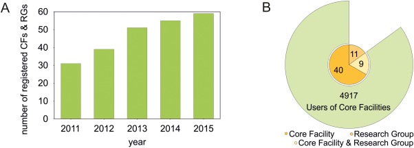
Development and current composition of the GerBI network. (A) Number of registrations per year. CF: ALM‐core facility, RG: microscopy research group. (B) Composition of GerBI: canonical core facilities (orange, 40), research groups (light orange, 11), and sites operating as both research group and facility (yellow, 9). The outer segment indicates the total number of users of registered CFs per year (status as of January 2016). [Color figure can be viewed in the online issue, which is available at wileyonlinelibrary.com.]
Between 2013 and 2014, GerBI installed working groups focusing on areas of particular interest, ranging from user training to facility administration to career perspectives. This review presents the results of this work to a larger audience in Germany and abroad. We set the stage by providing background information on the past and present funding situation of CFs in Germany. We then give advice to newcomers who might consider taking up a position as an imaging CF leader and give indications on best practice construction, operation, and administration procedures. Based on a survey conducted among GerBI members, we also formulate recommendations regarding the staffing of CFs.
Moreover, we devote space to the issue of data and image analysis, which is becoming the major bottleneck in bioimaging nowadays, as much as in other data‐intensive disciplines. Here, major efforts are made at the national and regional level, to develop efficient strategies for the management of large amounts of scientific data. With this article, we want to put microscopy center stage in the discussion about‐OMICS technologies, as this is still lagging behind. Finally, we give our perspective on the questions of career development and continuing education of CF staff.
Although this article mainly reflects our experience as leaders of German imaging CFs, many aspects can be applied to research infrastructures in general. This holds particularly true for facilities with direct user interaction, that is, where users are trained to work with the equipment by themselves, as in flow cytometry and, to a lesser extent, in electron microscopy CFs. The financial and administrative regulations described are peculiar to the German science system. Yet, some parts may apply for other countries, too. Thus, we hope that scientists seeking a position in the context of research infrastructure in Germany will find the information given here to be helpful. We also expect institutional administrations, faced with the task of installing a CF, to find inspiration in the present paper.
FUNDING OF CORE FACILITIES AND LARGE INSTRUMENTATION IN GERMANY
This chapter wants to provide an understanding of the German research funding system and how it may (or may not) provide opportunities for the financial support of distributed research infrastructures such as imaging CFs.
In the Federal Republic of Germany, funding of research and higher education is a common task of both, the Federal and the 16 State governments, their cooperation being regulated by the Basic Constitutional Law. With the Federalism Reform in 2007, those regulations were revised and full autonomy in cultural and educational matters was assigned to the individual States of Germany (Bundesländer). At the same time, a cooperation ban between government and states was introduced (“Kooperationsverbot”). Thus, the States bear all administrative and financial responsibility for the public institutions of higher education, i.e., Universities and Universities of Applied Sciences. The Federal Republic (Bund) may support these institutions only when funding infrastructure for research purposes. On the other hand, the large research organizations, i.e., Helmholtz Association, Max‐Planck‐Society, Fraunhofer Society, and Leibniz Association with their respective research centers, are jointly funded (with different quotas) by the Federal and State governments. For Helmholtz and Fraunhofer Association, for example, 90% of public funds are provided by the Federal government and 10% by the State of residence of the respective center.
This diverse system of research establishments and funding sources directly impacts CFs, because it determines the financial and administrative framework within which they operate. Depending on the hosting institution, different administrative and financial policies are implemented regarding e.g., the application and amount of user fees, the flow of third party funds, the availability of and allocation criteria for intramural funds, etc. The choices open to facility leaders for securing funding and sustainability to their facility vary accordingly. Therefore, different models for the administration of CFs coexist, reflecting the complex landscape of German research institutions.
In terms of establishing openly accessible research infrastructure, German universities are still lagging behind the large research organizations, a development that can be partly explained with the changes introduced by the Federalism Reform in 2007. Before the reform, the Federal government directly allocated 1,2 Bn. EUR per year to universities in the frame of the University Construction Act (“Hochschulbauförderungsgesetz”). About half of these funds went into large equipment for universities and university hospitals for research, education and patient care purposes. Under the cooperation ban the government ceased to support equipment devoted to educational or patient care purposes. This new regulation required an amendment to the Constitutional Law (Art. 91b) which restricted governmental funding for large instrumentation (between 200 TEUR and 5 Mio. EUR) to equipment devoted exclusively to research purposes. Furthermore, these funds are granted only if the State of residence covers 50% of the expenses. By this means, roughly 170 Mio. EUR are spent yearly for large research equipment. An additional 200 Mio. EUR are given by the Government to support the construction of new research buildings and equipment therein. For all other investments the States receive “compensatory funds” of roughly 700 Mio. EUR per year. Until 2014 these funds were earmarked for constructions in the area of higher education and healthcare, and thus represented a source of funding for larger instrumentation whenever universities and university hospitals acquired new buildings. Outside of this scheme, the acquisition of money for large equipment became difficult for universities, since the instruments very often are employed for both, educational and research purposes, and thus are not eligible for the federal budget. Altogether, this situation entailed a significant shrinkage of money for large scientific instrumentation in the university sector, in the absence of alternative third‐party programs. The only exception to the cooperation ban were special programs like the Excellence Initiative, which has spurred expenditures in large instrumentation. This initiative remained, however, strictly linked to specific projects and is conceived on a temporary basis.
In contrast, the large research organizations and their centers could rely on a stable flow of federal funds for decades and, therefore, were able to deploy internal programs for large instrumentation. Moreover, these centers are often organized as clusters of competence around a specific research topic. In such settings, it is easier to identify common interests in terms of technical equipment and agree upon investments as compared to universities which must cover a broad spectrum of different disciplines for higher education. In fact, in Germany, the concept of CFs for the life sciences was first implemented in the early 1990s at non‐university research institutions like the European Molecular Biology Laboratory (EMBL).
At universities, the main gateway to access funds for large instruments is the appointment of a new professor which follows established procedures and mobilizes both, university and state funds. In most cases, this process results in the choice of equipment being guided by a single and very specific research interest. The instrumentation then gets assigned to one particular research group, further hindering the idea of CFs at gaining ground.
The evaluation of applications from universities for large instrumentation funded through federal or state programs is in the hands of the DFG since the first implementation of the University Construction Act in the 1970s. Following the Federalism Reform in 2007 the DFG launched a new funding program for distributing the remaining funds of federal competence. This program was denominated “Art. 91b GG” according to the paragraph of the Basic Law which had been modified by the Federalism Reform. Because of the abovementioned reduction of the budget, the program introduced more stringent application requirements including a new “Supplement ‐ operating and usage concept for proposals for major instrumentation as per Art. 91b GG”. In this form, the applicant(s) must declare who will use the instrument, to what extent it will be shared between different groups, who is the responsible person and, most importantly, how the running and maintenance costs will be covered. For sure, this procedure has contributed to make university administrations and executives aware of the issue of the efficient usage of large instruments. It is probably from here, that the concept of CFs slowly started gaining grounds, also at universities: The institutions featuring as the “applicant” became increasingly aware of the large running and maintenance costs associated with instrument investments in the life sciences, which cannot be sustained by individual groups or even departments. User fees alleviate the burden by spreading it on many shoulders. Putting them into practice at universities, however, has not been easy and was quite uncommon until very recently. Also here, improvement came in 2009 when the DFG joint committee approved on fees for instrument usage as a regular cost item in grant proposals, if the applicant provides clear usage rules. In 2011, the DFG published minimum requirements for guidelines for instrument usage in order to justify the funding of user fees. Altogether, these trends ‐ a reduced budget for large research instruments, a sharper look of funders on their utilisation, the “fee for service” concept, and last but not least the increasing complexity of the instruments themselves requiring a dedicated expertise ‐ have led to a wider acceptance of CFs as necessary and important novel structural units at German universities. Since 2011, a new funding program of the DFG explicitly addressing CFs, provides further support. Many issues remain open though: First and foremost, the sustainability of CFs, but also issues referring to CF staff, e.g., qualification, level of appointment, and career path.
CFs as emerging novel entities in academia, bear the potential of setting new stimuli for the whole system of research and higher education beyond their primary task of providing state‐of‐the‐art research infrastructure. A unique opportunity may come from an amendment to Art. 91b of the Basic Constitutional Law, which was enacted in January 2015. It removes the cooperation ban and introduces new possibilities for the direct, long‐term funding of German universities by the federal government. Thus, there is a call for inspecting with attention the concept and the current situation of CFs and research infrastructures in general and take advantage of the new circumstances. Only if a national strategy for durable and dependable support is implemented, CFs will thrive and positively impact research and innovation, thus ensuring an adequate return of the large initial investments necessary to install them.
WHAT YOU SHOULD CONSIDER BEFORE STARTING AN IMAGING CORE FACILITY
To our experience, the decision to establish an imaging CF is made out of two reasons: (i) a group of influential principal investigators (PIs) with knowledge of and a high demand for microscopy decides to pool existing instrumentation into a core unit or (ii) the management of an institution makes a strategic investment in central research infrastructures. Frequently, in the first (bottom‐up) approach, the person to lead the CF is recruited among the PhD students or PostDocs who ran the microscopes in one of the groups of the participating PIs. The position of this person can be ambiguous, at least during a certain transition period, when he or she may still be regarded as a collaborator of that group. A clear job description, including the level of responsibility, the involvement in research work and the amount of teaching load, will help redefining the position and switching to the new role. If the facility is founded following an institutional initiative, these issues usually are discussed beforehand and the candidates are more frequently recruited from outside. The challenge in this case, is to build up the CF de novo in an environment oftentimes lacking expertise and within a time frame set by non‐experts.
One of the first objectives after being appointed facility leader is to understand the decision making processes within the hosting institution or department: Who is responsible for the funding, who decides about instrument purchases and employments, how is space allocated? Most likely, several people at different levels will be involved. It is advisable for the facility leader to meet with them in person and illustrate the strategy for building/running the CF. It is important to convey a vision of how the facility could develop within 5 − 10 years. This prognosis should be based on the CF leader's microscopy expertise and a good knowledge of the research interests of the prospective users. The latter can be acquired through semi‐standardized interviews that should be conducted as soon as possible.
CFs may be supported by and need to serve more than one department or institution. In this case, it is important to install an interdepartmental or inter‐institutional steering body. The facility leader, if possible together with members of this committee, should elaborate a concept paper which sets the frame for the operation of the CF. Cornerstones for the facility plan are the number of instruments that will be integrated and, consequently, the need for staff support. Furthermore, the concept paper must delineate governance rules, financial and administrative rules, access policy, allocation of personnel, competences and tasks of the facility leader, and last but not least, a policy for acknowledgement of facility services in publications. The continuing education and career perspectives of the core staff should also be addressed. Permanent positions are essential to secure the technological know‐how, but are difficult to obtain. Space issues might become critical with time, so it is advisable to plan some additional rooms for expansion. If and to what extent the facility should pursue research work and collaborate with commercial partners are also fundamental questions that should be fixed in such a concept paper.
Importantly, the designated facility manager should reflect on his or her own motivation and aptitude for the job. The goal of an imaging CF is to enable scientists to successfully apply (advanced) imaging technologies to their projects and perform top‐level research. Besides excellent technical skills, a good imaging facility manager thus should be able to reach out from his educational background into other disciplines: a physicist will need a good knowledge of biological sample preparation to assess the feasibility of a project; similarly, a biologist needs a sound foundation in optics and photophysics to judge the options and limitations of microscopy techniques. The demand for image analysis is huge, too; some expertise in this area is extremely helpful. Additionally, excellent communicational and interpersonal skills are a prerequisite for a good CF manager. Users have different levels of experience and scientific maturity, ranging from undergraduates to advanced postdocs or PIs, and the tasks of a CF manager are as diverse as basic user training, assessing the most promising microscopy technique for answering a specific question, or convincing a group leader that a project is technically not feasible. Above all, core managers must have a service‐oriented personality, with the ambition to create a strong and reliable infrastructure that provides the optimal scientific and technical support to its users.
HOW TO DESIGN, SET UP, AND RUN YOUR IMAGING CORE FACILITY
Choice Criteria for Equipment
In the first place, the equipment in a CF must be chosen according to the needs of the users. This will also determine the ratio of basic to very specialized instruments. If an institution or department is focused on a particular scientific area and is performing cutting edge research in this field, then it will be important to purchase instruments tailored to these particular types of investigations. On the other hand, if a broad and fundamental support in imaging is requested, then a sufficient number of general‐purpose microscopes, like laser scanning confocals and widefield systems, should be acquired and their utilization optimized. In addition, it is advisable to gather information about nearby laboratories or facilities and their equipment. It might not be worth purchasing an expensive stimulated emission depletion (STED) microscope, if one with the required configuration is available in an institute across the campus.
Another important aspect is the on‐site support by the manufacturers. The quality and promptness of the service provided by companies may vary depending on the local area. Hence, it is best to confer with colleagues on the campus about their experience. For small facilities it can be of advantage to purchase equipment from one or two providers only, if the product portfolio is suitable. In this manner, prices for service are reduced, since one technical expert can take care of several instruments during one visit. In addition, objectives and optical parts can be swapped easily between different microscopes. For bigger facilities, interacting with several different companies gives the opportunity for competitive price negotiations, in particular when purchasing new equipment.
Organizing Space and Installing Equipment
When a new microscopy facility is installed, laboratory space needs to be properly organized and equipped. We recommend to draw a plan of the rooms including all existing items beforehand to identify the best position for the microscope system(s). General requirements for the lab space layout and installations for light microscopes in CFs have been described in great details elsewhere (Kling, 2010; Mayer, 1995; Murphy, 2002). Here, we devote particular attention to multiphoton (MP) and super‐resolution (SR) microscopes. The new developments enabling to dramatically improve resolution can only be utilized if unwanted movements of the stage or the objective are well below the resolution. Although image post‐processing can remove some movement artifacts, it is advisable to minimize them as much as possible in the first place. The room temperature and vibrations transmitted via floor and walls have a major influence on the stability of the laboratory environment.
Temperature Stability
Air conditioning must be planned according to the heat load of the instruments in order to achieve a stable working temperature. Standard microscopy rooms without specialized air condition devices may show temperature variations of several degrees Celsius within 24 h. To provide highest performance, SR microscopes usually require a temperature stability of ±1°C. Since some of the microscopes have a waste heat production of around 5 kW, sufficient temperature stability can only be achieved with high air exchange rates. These, however, decrease microscope stability. One solution can be additional air conditioners or cooling convector units, which can be activated upon demand. Cooling convector units consist of many ventilators. They are supposed to provide draft‐free transfer of air. Alternatively, air conditioning systems with large air outlets i.e. air socks and textile diffusers have proven useful. In these systems, many small outlets distributed over a large area generate the required high air exchange with a comparatively small air flow per individual outlet. It is important that the cooled air is neither blown onto the microscope, where it would cause vibrations or temperature fluctuations, nor onto the user, to prevent discomfort due to cold air downdrafts.
Having a room layout which includes the positions of the microscope(s) and the users will help planning the climate control strategy. The key factors are: (1) set‐point on temperature controller or thermostat (can be either locally in room or centrally controlled), (2) input air temperature and volume, (3) air cooler operating point and capacity, and (4) heat load into room. Very often heat is produced at a few points (e.g., Argon laser ventilator, MP laser chiller) and can be discharged into an exhaust system directly from there. Tight connection should be avoided, though, because this can cause overheating if the exhaust system fails. One may also consider insulating the hot air exhaust tubes to prevent thermal radiation into the room. Alternatively, outsourcing lasers and electronic devices to adjacent supporting rooms has proven to dramatically increase temperature stability in microscope rooms. Such support rooms need to be in direct vicinity of the microscope setups, since some lasers have short, around 2 m long preinstalled light guides. Vertical sliding doors (about 60 cm x 60 cm, with a brush seal at lower edge) between the support room and the microscope room, approximately at 1.20 m above the floor will be of great help during installation and maintenance.
Other common sources of disturbance are cooled water tubes connected to air conditioners. During warm and humid weather, condensation water can drip onto the microscope or the whole system can leak water. Therefore, a second ceiling or a collection pan above the microscope is highly recommended, preferably with a coupled water sensor to detect leakage.
Vibrations
Image quality is impaired by vibration, so great attention should be devoted to reducing it to a minimum. Excluding shakers, ultracentrifuges, pumps, compressors, refrigerators, vending machines, autoclaves, or elevators in the neighborhood is a good start to generate a vibration‐free environment. Also, strong automatic door closing devices should be omitted. The use of sophisticated optical table systems is advisable for advanced imaging setups. Additionally, be aware of sources of vibration inside the microscopy room, which include pumps, MP power supplies, MP laser chillers, or fans for incubation chambers. Contact of microscopy equipment with the walls should also be avoided. Even indirect contact via electric cables can transmit vibrations. Here, instrument racks with power sockets will help to decouple vibrations from the wall to the microscope setup.
Electricity and Gases
In addition to temperature and vibration aspects, an outline of the microscopy room and infrastructure should comprise planning of power supply and gas lines. The number of electrical sockets and their positions in the room, as well as the number of independent circuits or fuses, need to be determined beforehand. Here, one should think ahead in order to include options to add equipment to the system in the future (e.g., gas mixers, pumps, micromanipulators, incubation chambers, surgery equipment, etc.) It is important to consider whether or not an uninterruptible power supply (UPS) is necessary for sensitive equipment. But be aware that a system running on a UPS is not shut off by the emergency stop! Gather information about the emergency stop at an early stage: Find out what is affected (e.g. power and some gases) and what the reset procedure is.
The lights in the room are important, too. Some users prefer lights which can be dimmed, others small desk lamps. For some applications (e.g. external detectors), the rooms need to be completely dark. This includes the installation of blinds at door windows and brush door sweeps. In rooms where genetic safety and security rules apply, permanent covering of door windows may not be allowed. In this case, blinds which can be opened from the outside are an alternative.
Furthermore, gas supply required for the experiments needs to be planned. Compressed air for anti‐vibration tables or gas mixers (such as CO2) is standard, but gas cocks with different operating pressure ranges may apply. CO2 is needed for live‐cell imaging and carbogen (5% CO2, 95% O2) for acute slices. In some cases, N2 is required. Find out if the emergency stops also interrupt the gas flow and if oxygen sensors are needed in the rooms. Depending on gas consumption, bulk supplies or cylinders need to be considered, in addition to the positions of gas cocks in the room.
Staffing the Facility
In June 2015, GerBI conducted a survey among its member CFs to analyze the current situation regarding staffing and instrumentation. 31 facilities participated in the survey, 27 were included in the evaluation of the data set.
The size of imaging facilities in Germany varies broadly, ranging from two instruments supported by one person to 30 instruments supported by 5‐7 persons (Fig. 2). There is a tendency to facilities with 1‐2 employees. Within this group, the number of instruments varies widely (2 − 20). The extent and quality of the support these CFs can provide will vary accordingly. The imaging facility indicated by the circle in the lower right corner of Fig. 2A (5 instruments, 9 employees) is exclusively dedicated to high‐throughput screening and thus represents a special case.
Figure 2.
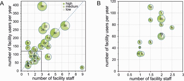
Characteristics of a representative group of German imaging CFs. (A) The graph displays the number of facility users per year (y‐axis) vs. the number of supporting staff (x‐axis). Each circle represents one CF. The size of the circle depends on the number of instruments, which is shown inside. The circle sectors indicate the proportion of high vs. medium vs. low level systems. The systems were defined as follows: High: Superresolution microscopy, fluorescence correlation imaging, MP and nonlinear imaging, light sheet imaging, laser capture microdissection; Medium: Point scanning and spinning disk confocal, total internal reflection microscopy, fluorescence resonance energy transfer; Low: Wide‐field, deconvolution, and stereo microscopes. The dashed line indicates the median user/staff ratio. (B) Enlarged view of the inset shown in (A). [Color figure can be viewed in the online issue, which is available at wileyonlinelibrary.com.]
A median user‐to‐staff ratio of 46 was calculated from these data. 12 CFs among those that participated in the survey operate below this value (Fig. 3). Regarding the level of experience of CF staff, the survey showed that all CFs employ at least one person holding a doctoral degree; in total, 69% of facility personnel has a PhD, reflecting the need for scientific and research expertise in CFs.
Figure 3.
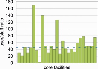
User to staff ratio in German ALM‐CFs. Each green bar represents one facility. The blue line indicates the median. [Color figure can be viewed in the online issue, which is available at wileyonlinelibrary.com.]
During the 6th GerBI Annual Community Meeting in July 2015, recommendations for the staffing of imaging CF were discussed and unanimously approved by the participants based on these data. A user/staff ratio of 45 : 1 is seen as the highest possible to provide adequate support on medium level systems. A lower ratio applies for more sophisticated instruments like superresolution microscopes. Furthermore, it was agreed that a CF should have at least two employees to ensure continuous operation and cover vacations and sick leave.
Overall it can be concluded from these data that CFs frequently operate at or even beyond the limit of their personnel capacity. In this respect, it is important to consider that the number of available instruments alone does not ensure useful and effective service to the users, but that sufficient staff to teach users and maintain instrument quality is essential.
We therefore also aimed at defining an optimal instrument/staff ratio, and collected recommendations for this parameter via a poll among the participants of the abovementioned community meeting. Different percentages of one full time equivalent (FTE) are needed to ensure adequate support depending on the complexity of the microscope. An estimation of optimal instrument/staff ratios was made assuming 50% average usage or 2 − 3 users per instrument and day (Table 1). Less staff might be needed if a CF harbors several identical instruments or, if only few power users have to be trained and assisted. More staff will be required if support in image processing and quantification is requested too, and if the institution puts emphasis on individual and customized user support, including the establishment of new or modification of existing imaging methods, help with sample preparation and provision of customized image analysis solutions.
Table 1.
Recommendations of GerBI for the staffing of imaging CFs
| Recommendation | FTE | based on |
|---|---|---|
| minimum | 1 FTE per 45 users; 2 FTE per CF; at least 1FTE holding a PhD | median user/staff ratio (GerBI survey June 2015, see Fig. 2 and Fig. 3) |
| optimum | per LS system: 17%/FTE; per MS system: 28%/FTE; per HS system: 53%/FTE | poll solicited among participants of the GerBI Annual Community Meeting 2015 |
FTE, full time equivalent; LS, low level system; MS, medium level system; HS, high level system; see also legend to Fig. 2.
Assessment of Instrument Performance
One of the main tasks of an imaging facility is to monitor and maintain the optimal performance of the microscope systems hosted by the facility. In a multi‐user environment, microscopes are prone to contamination, misalignment or even damage of optical components. Regular system checks should be common practice and measure e.g. the point spread function (PSF), the laser power, the illumination homogeneity of the field of view, the detector sensitivity as signal‐to‐noise‐ratio (SNR) and the coefficient of variation (Cole et al., 2011, 2013; Gelman and Rietdorf, 2010; Hibbs, 2006; Stack et al., 2011; Theer et al., 2014; Zucker and Price, 2001, 1999). When performed regularly, standardized test series often help identify damaged and misaligned microscope components, even before they significantly impair the quality of user data. Hardware defects frequently arise at objectives, illumination units, scanners, pinholes, and x/y/z translation devices. Table 2 lists common sources of performance decline together with the measurements which can help identifying the source of error. It is important to note that any troubleshooting will only be successful, if all other parameters (i.e. your test sample quality) are maintained and if the initial performance of the setup is known. In addition, for most of the mentioned tests it is important to switch the microscope on well in advance. To this end, the required system warm up time should be determined, for example by identifying the positional stability of a fluorescent bead over a 15 min time‐lapse recording (Table 2 row H1) or by means of a multi‐position experiment (Table 2 row H2). After switching on the microscope, the total apparent displacement of beads within a given time frame will decrease. The instrument should be warmed up for at least the amount of time required to minimize this displacement (or a reasonable approximation thereof). Depending on the degree of motorization and the illumination sources used, warm up times can change considerably. Frequently observed warm up times of advanced light microscopes amount to up to 3h. Unfortunately, software and computer issues are also among the most frequent reasons for malfunction. Yet, they are hard to predict and in many cases have to be solved by the microscope manufacturer.
Table 2.
List of test measurements for maintaining microscope performance
| Source of performance decline | Performance test | Time | Practical considerations | |
|---|---|---|---|---|
| A | Objective |
1) visually inspecting lens surface 2) PSF measurements |
1) 5 min 2) 15 min |
Clean, if required incubation o/n in water‐based cleaning solution. Measure PSF with another lens to identify damage source. If PSF with second objective is OK, send first objective to repair, if PSF with second objective shows the same abnormality, then perform tests B2, D, E, F, and H. |
| B | Illumination |
1) Stability over time 2) Field illumination homogeneity 3) Power |
1) 3h 15min 2) 5 min 3) 1 min |
Check for B, E, and F. Use recommended magnification or zoom settings, open pinhole, realign illumination beam path, and test for A, D, and E. Realign illumination beam path and clean lenses or filters in beam path. Replace illumination and fiber. |
| C | Chromatic aberration | Measurement of chromatic aberrations in x, y, and z direction | 15 min | Avoid changing dichroic mirror between channels. Check for A and B2. |
| D | Pinhole | Test pinhole position | 5 min | Measure intensity of sub‐resolution beads. If the intensity does not increase by more than a factor of 3 as diameter of pinhole is increased from 1 AU to > 2 AU, the position is good. If the increase is larger, adjust pinhole position. |
| E | Scanner | scan field uniformity | 15 min | Use recommended zoom and speed. Also test F and H. |
| F | Z‐drive |
1) Stability over time 2) Repositioning precision |
1) 20 min 2) 5 min |
Make sure the stage is firmly fixed, joystick is at “no move” position, and specimen is at environment temperature. Test for stability when all pumps, perfusion systems, heating devices etc. are switched off and when air conditioning and ventilation are switched off or protect microscope from draft with dust cover. Test for H. |
| G | Detector |
1) Measure instrument dark noise. 2) SNR and coefficient of variation measurements |
1) 5 min 2) 10 min |
Test also B, E, F, and H. |
| H | XY translation stage |
1) Stability over time 2) Repositioning precision |
1) 20 min 2) 5 min |
Same as for F. Test for F |
Regularly performing all checks and calibrations listed in Table 2 will cost a considerable amount of imaging time and man power. Some CFs employ students for some of the routine procedures. Which calibrations make sense and how often they should be performed will vary between CFs, depending on the number of users and their levels of experience as well as the type of experiments. In addition, it is useful to store the results from performance tests in a database/data management system. This enables tracking of changes in e.g. the shape of the PSF, the field illumination, the laser power etc. over time. Several image analysis tools and macros for evaluating performance tests and managing the corresponding data are available (MetroloJ/Fiji, (Hng and Dormann, 2013), PSFj (Theer et al., 2014)). Ideally, the standardized performance test procedures should be designed in collaboration with engineers from the manufacturing companies. To this end, it would be extremely helpful if microscope manufacturers shared test samples and protocols with experienced facility personnel to enable self‐contained, qualified diagnoses of performance problems.
Safety Aspects
Microscopy rooms primarily need to comply with institutions’ general and work safety rules, as any other room designed to host personnel. All the safety aspects of the microscopy rooms need to be carefully examined and discussed with the safety office of the hosting institution. However, there are several safety aspects specific to microscopy rooms that we want to briefly discuss here.
Laser Safety
Most commonly used laser devices in microscopy belong to class 3B and class 4, which have the potential to injure humans. Commercial systems fullfill high laser safety criteria and are designed to avoid exposure of the user to laser light. Particular attention is needed when imaging systems are custom designed to enable coupling of external lasers in free space. Exposure to the direct laser beam (class 3B) or even an indirect laser beam (class 4, e.g., reflected from matte surfaces), may entail injury, usually of the eye or skin. Additionally, secondary hazards, like for example laser‐induced fire, need to be considered, especially if flammable liquids (such as ethanol) are stored nearby. Both, room and instrument, must be labelled with internationally recognized laser illumination warning signs. A safety officer specialized in laser safety needs to examine and certify the room and the instrument before it can be operated by the users. Moreover, the facility personnel are recommended to attend a laser safety training in order to be able to officially act as laser safety officers.
Gas Safety
Live cell imaging is a much sought‐after microscopy technique which requires a CO2‐enriched (5%) atmosphere in the microscope environment control box. The necessary CO2 supply in the room can be installed as a dedicated gas outlet with various pressures (usually 1 bar) or in the form of gas cylinders (10‐25 l, 150‐200 bar). In the case of a gas valve malfunction, CO2 levels in the room can rise quickly, especially if high pressure gas cylinders are used. CO2 levels above 1000 ppm cause headache, drowsiness and impaired cognitive abilities. Levels above 5000 ppm may have adverse effects on health and levels above 50000 ppm cause intoxication and death. For this reason, the room and the requirement for CO2 supply must be assessed by a safety officer specialized in gas safety. Depending on the size of the room, the amount of CO2 stored and the room ventilation rate, installation of a CO2 monitoring and alarm system may be necessary. The safety aspects of other gases that may be used in the context of microscopic investigations (for example O2, N2, gas for animal narcosis etc.) are beyond the scope of this text.
Another topic that loosely fits in the category of gas safety is the explosion of a mercury‐based light source. In this case, the air space may fill up with toxic mercury vapor and, therefore, the room will need to be vacated immediately. Modern LED‐based light sources are superior to mercury lamps and will likely displace them in most microscopy applications in the coming years.
Biosafety
The general safety rules that apply to any area exposed to genetically modified organisms (GMOs) obviously also apply to microscopy rooms. GMO related documentation usually is the user's (group leader) responsibility. The imaging CF, however, needs to also record what types of GMO are examined using the microscopy infrastructure. Documentation thereof can be implemented in the booking procedure where users need to specify the type of biological sample they are working with. In special cases requiring an enhanced biosafety environment (for example research on infectious human pathogens), the microscopy room will need to be certified for usage under biosafety level (BSL) 2, 3 or 4 in close collaboration with the institution's biosafety officer. The respective regulations vary between countries, pathogens and the type of experiment. Yet, there are general strict rules regarding disinfection procedures within an enhanced biosafety area. All equipment and material will need to be sterilized before leaving the biosafety area. Various sterilization procedures exist, depending on the biosafety level. Microscopy equipment must be compatible with the respective disinfection procedure. Furthermore, all surfaces have to be easily accessible for disinfection in case of a spilling accident. All cables, thus, need to be carefully managed so that nothing is on the floor and tables. Furthermore, the holes in the optical table/breadboard often need to be covered. If wearing a full face mask or goggles is required (BSL3 and 4), this will impair the operator's ability to visually assess the sample through the ocular. Manufacturers can be asked to custom‐build oculars with a very long focal distance. Keeping the necessary set of microscopy maintenance tools within the enhanced BSL area is recommended. Some safety operations may interfere with microscopy, e.g the automatic test procedures for the mandatory emergency lights should not coincide with sensitive imaging experiments; the necessary high rate of air exchange may compromise temperature stability (see above); in the case of airborne pathogens, decontamination by fumigation with formaldehyde or H2O2 vapor is the method of choice, but will damage microscope components, so alternative procedures must be considered.
Proper implementation of the safety aspects mentioned here is crucial to minimize the risk of injury associated with usage of microscopes. Each user needs to be briefed about the potential hazards and safety rules in microscopy rooms. To ensure this, a comprehensive “Terms of Use” document that covers general and microscopy‐specific usage rules should be signed by each user. On top of that, all safety aspects need to be re‐iterated during the introductory session. Compliance with some safety aspects, such as laser safety and bio‐safety, requires the organization of an annual user training seminar. This will ensure the establishment and maintenance of high safety compliance standards necessary for maximum human safety.
Facility Administration
Financial Framework
Some key areas of facility administration must be covered with due care, in order to make sure that the imaging CF will operate smoothly and sustainably in the long run. One of these is the mode of facility financing for which different options exist. From the perspective of a CF, the easiest way is full funding by the hosting institution. In most cases, these facilities do not charge fees for their services (instrument usage and assistance time). This model, however, will only work out, if the facility serves internal users and collaborators. As soon as a considerable number of externals use the CF, the hosting institution will be interested in collecting usage fees.
Establishing such fees has several benefits. First, it is a transparent way of showing the cost of scientific work and instrumentation. Moreover, facility users are more likely to value the access to CFs, stick more stringently to the reserved time slots and take better care, if they have to pay for the usage of instrumentation. On top of that, usage fees are key to enable the open access concept – i.e. to open CFs to scientists from outside the hosting institution – and therefore help to increase instrument utilization and sharing. If fees are charged, a full economic costing (fEC) calculation is the basis for usage price determination. It enables the decision as to which costs have to be covered by CF users and which costs will be subsidized. Often, the hosting institution partially subsidizes instrument usage of internal users while fEC are charged to external users. In Germany, the costs for using CFs may be included in research proposals to the DFG. The accountable average rates vary from 15 EUR to 100 EUR per hour depending on the instrument type and mode of operation and were published by the DFG in 2011 (http://www.dfg.de/formulare/55_04/55_04_de.pdf).
Within the fEC model, direct costs generated by the usage of the CF and indirect costs covering infrastructure, as well as VAT (if applicable) can be distinguished. The full direct costs to run shared research infrastructure are composed of several cost items: 1. Service Contract, 2. Equipment Related Costs, 3. Facility Staff and 4. Depreciation. These items will now be explained and an example calculation for a ‘'typical’’ confocal laser scanning microscope (CLSM) will be given.
Service contracts including laser replacements are expensive but recommended for heavily used CFs. In Germany, for a standard CLSM service contracts currently amount to around 30 TEUR per year.
Instrument usage generates equipment related costs, such as expenses for repairs (e.g., lenses), small equipment (e.g., lenses and stage adapters) and consumables (e.g., filters, lamps, immersion liquid). As a rule of thumb, equipment related costs of about 10 TEUR per instrument and year have to be budgeted.
The constant presence of highly trained facility staff is crucial to maintain the state‐of‐the‐art equipment. On average 2 h per week are needed to properly service an instrument (e.g., cleaning, adjustment, measurement of laser power, and PSFs). This sums up to 100 h/year (2 h times 50 weeks). Moreover, facility staff is constantly needed for user support. On average, each hour of usage will cause five minutes of staff support, which, then, sums up to around 167 h/year (5 min times 8 h/day times 5 days/week times 50 weeks/year). Depending on the hosting institution, staff costs will be around 50 EUR/hour. For the example of the LSCM, this sums up to 13,4 TEUR yearly expenses for staff (267 h/year, 50 EUR/hour).
Depreciation is calculated differently depending on the hosting institution. For microscope instrumentation, it usually ranges from 3 to 13 years. For a LSCM that initially was bought for 500 TEUR a depreciation of 71,4 TEUR per year is assumed (500 TEUR/7 years).
The direct costs for running an LSCM can now be calculated as the sum of the expenses for a service contract (30,0 TEUR/year) plus equipment related costs (10,0 TEUR/year) plus facility staff costs (13,4 TEUR/year) plus depreciation (71,4 TEUR/year). As a result, the direct costs to run a LSCM will be around 124,8 TEUR/year. As mentioned before, indirect costs as well as VAT (e.g., for external users) have to be considered for the coverage of instrument infrastructure costs. Depending on the hosting institution, infrastructure costs (e.g., space, electricity, heating/cooling, administrative costs) are covered by an overhead that may be in the range of 30% of direct costs.
Full instrument utilization is counted in machine hours and defines the number of usage hours per year that represent 100% instrument usage. As a common basis, ∼ 1600 machine hours per year (∼40 weeks/year times 5 days/week times 8 h/day) refer to 100% instrument utilization. This estimation takes weekly maintenance and instrument downtime into account. The usage price at full instrument utilization is, then, calculated by dividing the sum of the direct and indirect costs by 1,600 h. In the example of the CLSM, this means that direct costs of 124,8 TEUR/year are divided by 1,600 h assuming full instrument utilization by internal users. The resulting usage price per machine hour is 78 EUR.
Some funding agencies do not allow instrument depreciation to be factored in. In the CLSM example, the fees per machine hour would, therefore, drop to the typical usage price range of around 33 EUR/hour for internals. In contrast, covering full economic costings, external users will have to pay around 120 EUR/hour for the example CLSM (including 30% overhead and 19% VAT).
Some institutions offer a third “collaborator” user group beside internal and external user groups. The idea is to charge all groups according to the same cost basis, but including different sets of costs. Externals, for example cover full costs, while collaborators do not pay indirect costs and internals pay neither indirect costs nor instrument depreciation.
Very often, a CF hosts several comparable instruments. To our experience, it is useful to calculate the usage price as a mixed price regarding to instrument groups instead of individual instruments. We categorize comparable instruments in groups, e.g., CLSM or live cell widefield systems, and calculate the usage price in a mixed calculation including the costs of all instruments in the group. Otherwise, the yearly recalculation of the usage price will result in considerable changes, as well as differences between technically comparable instruments. With a mixed calculation, comparable prices for comparable instruments can be offered. Researchers, thus, get the chance to choose the instrument depending on the applicability for the investigation alone and not based on usage price.
It must be noted that in this example, costs for image analysis as well as for CF staff training, including travel money, are not considered. The latter point refers to the very important issue of maintaining high‐level expertise in CFs (see below).
Usage Rules
Independently of the size of an imaging facility and the number of shared research infrastructures, it is clear that each user community has to agree upon a set of rules that allow efficient and sustainable CF usage. It is highly recommended to put these guidelines in written form, so that users and PIs can read and accept it. In case of the imaging CF being part of a larger technology platform, the user must agree to the general rules of the technology platform first and, in a second step, to imaging facility‐specific usage rules or guidelines. We are fully aware of the fact that not all situations that may arise in real life operation of an imaging facility can be covered by written rules. Thus, we recommend to add a paragraph asking users to always consult the facility staff when in doubt. The following item list covers typical, general usage rules that apply in many imaging CF.
Safety rules
General safety
Laser safety
Safety procedures related to usage of mercury based light sources
Safety rules that apply for work with Genetically Modified Organisms (GMO)
-
Rules related to booking:
How to create a booking, how to modify and cancel bookings
How to offer slots that were booked but will not be used
Booking restrictions
Payments information (including fees)
Problem reporting
Reporting of misuse of the CF by other users
User admonishment in case of misuse of CF
Rules regarding IT infrastructure and data storage
Acknowledgements and co‐authorship policies
Software to Manage Imaging Facility Operation
The set of tools needed for the administration of a research CF crucially depends on its size in terms of number of instruments and users. Many facilities start small and can simply be organized by a pen and paper approach at the beginning. As facilities grow and start attracting more instruments and—especially external—users, more professional organization tools will be required. For a large user community, e.g., online scheduling (booking) systems are clearly needed.
Facility management software tools are challenged to cover a broad portfolio of needs and features. Here, we provide typical requirements that such software tools should comply with.
- From the user perspective:
- Reservation and cancellation of CF bookings
- Reservation and cancellation of assistance (staff) bookings
- Reporting problems
- Changing registration information and contact details
- From the PI's perspective:
- Information about the time group members spend in individual CFs
- Information about money spent for CF services (if applicable)
- From the facility's perspective:
- Registration of users to the system
- Enabling/disabling access of users
- Restricting booking (time slot) length
- Blocking of instruments (for service and maintenance)
- Absence of staff (meetings, sickness, holidays)
- Trouble tracking (with interface to users and companies)
- Usage tracking and statistics
- User project management
- Setting the price for instrument usage and assistance
- Harmonize user credentials between microscopes and IT (e.g. Lightweight Directory Access Protocol, LDAP)
- From the administration and management perspective:
- integrated invoicing
- easy data export to third party invoicing software
- easy access to the usage statistics
There is a plethora of software that is currently available for facility management tasks. Some software primarily covers instruments only, while some more complex, usually commercially available software tools cover broader needs. In some cases, software is written on demand for specific hosting institutions addressing all local needs, but freeware solutions are also available. Readers who are interested in further information on this topic can visit the GerBI wikipage: http://www.germanbioimaging.org/wiki/index.php/Manufacturers. We also suggest to consult a paper from colleagues at Friedrich Miescher Institut for Biomedical Research in Basel (Switzerland), who developed a complex user management system for their facilities: http://www.imaging-git.com/science/protocols/enhancing-efficiency-resource-use.
Training of Core Facility Users
Typically, between 50 and 300 users per imaging CF and year benefit from the scientific advice of facility personnel. Training is one of the key activities of a multiuser facility and must be provided at two different levels: on one side, users of the facility must be trained so that they can independently and efficiently perform their experiments without interfering with the work of other users. On the other side, facility staff needs continuing training as well, in order to be able to provide state‐of‐the‐art service and support (see also Chapter on “Ensuring high level expertise in Core Facilities”).
Usually, user training is one of the most time‐consuming activities in a light microscopy facility. Therefore, it is important to efficiently organize training activities, which can be categorized as follows:
User Counseling
When starting a research project involving microscopy, users need advice on several aspects, including sample preparation, the choice of imaging technique as well as the selection of the most suitable instrument and fluorophores. These demands should be discussed in an introductory meeting, followed by the actual training on the microscope. As mentioned above, users must be informed about the terms of use of the CF during this meeting, as well as of the rules of good laboratory practice and relevant institutional policies. User counseling is a task extending for the whole duration of projects: beeing able to operate the instruments does not necessarily imply a user's capability to correctly interpret the data or develop further experiments. Assistance on how to improve data quality is also frequently requested. Subsequent to data collection, users often ask for advice on how to best perform image analysis. Depending on the resources of the facility, users may be supported directly or referred to experienced colleagues or dedicated service units.
Theoretical Microscopy Knowledge
Usually, during a practical introduction to microscope usage, there is not enough time to teach much theory of microscopy. Knowledge thereof, however, would help avoid erroneous data acquisition and inaccurate interpretation. A convenient and simple way to ensure that users have minimum background knowledge are mandatory online classes and tests, like those provided by the Australian Microscopy and Microanalysis Research Facility (AMMRF; http://li155-94.members.linode.com/myscope/). Experienced users will quickly go through the test, others have the opportunity to acquire the necessary basic knowledge through the online tutorials.
Another possibility of user training is to offer dedicated microscopy courses. Advice on how to structure these courses can be found at the GerBI homepage. Here, templates for course contents and detailed recommendations on course contents, student/teacher ratios and student/instrument ratios are provided. Still, enabling users to operate an advanced imaging setup to address the research questions, requires customized training sessions for each user. Although this task is extremely time‐consuming, it remains the most efficient way of teaching, in particular in facilities with many different setups, where users perform a broad range of inherently different experiments.
A useful structure for a user training procedure (based on (Anderson et al., 2007; DeMaggio, 2002; Trogadis, 2006) and GerBI workgroup 5 surveys) is as follows:
-
Meet with the user to discuss experimental needs as well as prior knowledge and practice regarding microscopy. With this information, the best instrument for the user can be identified and a tailored training scheme can be developed. In addition, advice for improving sample preparation for microscopy can be given. It is also important to discuss user needs with regard to image processing and data management.
Topics to be covered during this session are: sample species, sample mounting, number of samples, fluorescent labels, 2D or 3D acquisition, live or fixed samples, desired magnification and resolution.
-
Have a first training session that focuses on the technical details of the instrument and microscopy theory relevant for the user. This session is ideally performed with a “neutral” sample, so the user is not distracted by specific experimental concerns.
Topics to be covered during this session are: switching the system on and off, setup of the appropriate beam path, filter settings, acquisition speed, pixel size, resolution and magnification, saturation and bleaching as well as how to store and reload microscope settings.
-
In a follow‐up session, the user should develop an experimental setup suitable for the biological question together with facility staff. Now, the user is supposed to bring his or her own sample, apply the newly acquired knowledge and use the instrument hands‐on. Topics to be covered during the third session are: adjusting of imaging conditions to user sample and a check as to whether the user is able to set up imaging parameters properly on his own.
The first images produced without assistance should be discussed: What can be improved in terms of image acquisition? How can the images be interpreted (and how can't they)? Which options for further analysis are available?
Overall, new users usually need several hours of attention before they can confidently operate an instrument and produce reliable results alone. (Whether or not a user actually fully understands what he or she is doing is the user's responsibility in the end. Attempts to force someone to this point can be tedious and will probably not be successful, if the user is lacking motivation.)
Quality Assessment of Scientific Output
It is in the interest of research institutions that data obtained in CFs complies with highest scientific standards, and moreover, that they are reproducible and robust. Imaging facilities are so‐called “user facilities” where instruments are operated directly by trained users. In most CFs, the large number of users with their very diverse imaging projects does not allow for a proper quality control of the acquired and processed data by the facility personnel. Thus, the responsibility for the project, including the experimental design, the quality of the results as well as the compliance to good scientific practice lies in the hands of the project leaders. CFs, however, can offer proofreading of the methods part of relevant publications. In projects where the facility staff is fully involved in the experimental design, data acquisition and/or analysis as well as interpretation, they should take responsibility and request co‐authorship on publications. In both cases, it is important to agree with users on the level of involvement and responsibility taken over by the CF when starting a project.
DATA ANALYSIS AND DATA MANAGEMENT
Modern advanced light microscopy gives access to a large range of spatial and temporal resolutions depending on the biological questions and the microscope setup. Imaging scientists may acquire very large amount of data encoding multi‐parametric feature spaces, bringing up the question of how to reliably extract the information content.
The biomedical scientist nowadays is confronted with the fact that digital image processing and data analysis in general turns out to gain a highly prominent status within the entire experiment pipeline (Fig. 4). In fact, a shift of this weighting towards bioimage informatics within quantitative biology is to be expected more and more in the future. In this context, both the computational instrumentation and, moreover, the ability to apply image and data analysis will define the future perspectives of scientists in the life sciences (Carpenter et al., 2012; Eliceiri et al., 2012; Myers, 2012).
Figure 4.
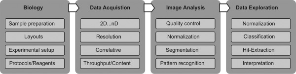
Experiment pipeline of a standard approach within quantitative biology. The figure depicts the information flow from the (i) biological approach, (ii) data acquisition, (iii) image analysis up to (iv) data exploration including the interpretation of the underlying biological process.
Recommendations for IT Infrastructure
The requirements for suitable data analysis capabilities and software solutions are strongly affected by the design and internal policies of the imaging CF in the context of data storage, data management, and data analysis.
Ideally, the CF is fully integrated in an existing data management and data analysis IT infrastructure. In this case, microscope raw data is directly transferred to a centralized data storage system enabling data to be processed in parallel. The imaging CF has to provide a reasonable user‐, group‐, and project‐management with internal and external accessibility to the image raw and analysis data. Self‐sustaining facilities with no access to such IT resources have to set up their own infrastructure. Assuming that the facility offers full support for image analysis, i.e. processing performed either by facility staff or by the user itself (using facility resources), the computational instrumentation still strongly depend on the number and types of microscopes. While for facilities equipped with standard microscope setups (e.g. wide field and confocal) a reasonable number of standard workstations1 is sufficient, at least high‐performance workstations2 and ideally cluster processing should be considered in case of advanced imaging facilities (e.g., super resolution, light sheet, and high‐throughput/high‐content microscopy).
In the context of data storage and data management systems, easy to configure data servers are commercially available, which offer reasonable storage capabilities including backup functionalities as well (order of magnitude: TB). Individual image analysis workstations then act as clients within this local intranet (Fig. 5). The central data servers enable transfer and storage of microscope raw data and can in parallel host the CF administration system. As a side effect, valuable microscope resources are saved by not allocating the instrument's computing power for image processing purposes. In case that the facility policies intend to provide long term data storage, the installation of an image/data repository and preferably a data base, respectively, with external access to image raw data and analysis results might be beneficial.
Figure 5.
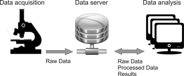
Image raw data is written and stored on a centralized data server, ideally featuring an integrated image/data repository and preferably a data base, respectively. The server ensures user and data management and external access for data analysis workstations.
Data Handling and Structure
Image Annotation
Imaging facilities in general hold diverse imaging setups for different purposes and from different manufacturers. As a consequence, different manufacturer‐specific proprietary image raw data formats have to be considered, although most of the microscope developers support a direct export of the image data to the Tagged Image File Format (TIFF). In any case it is of utmost importance to deal with file formats fulfilling at least the minimum standard of common universal readable data containers for not being restricted to the manufacturer's analysis software. Such a universal standard is given by the Bio‐Formats project (Open Microscopy Environment (OME), http://www.openmicroscopy.org/site/products/bio-formats) which addresses most of the commonly used image file formats. In addition to the image data itself, this standard guarantees to retrieve so‐called metadata, too. The metadata block of an image file is located in the file header and provides image related information like pixel data, dynamic range, dimensionality, experiment settings etc. In addition, the OME standard enables the conversion of proprietary file formats to the OME‐XML data model featuring the TIFF image file format and an XML metadata container block.
Data Access
Two types of imaging facility‐internal policies define how access to image data is granted. Under an (i) autonomous user management, the users themselves are responsible for data management (in the user‐accessible folder system). The image data is removed from the facility's infrastructure after the experiment is finalized. In case of a (ii) full user support including data management and (long term) data storage, the folder structure should be given by the facility and follow a clear hierarchical order (e.g., ‘/group/user/project/experiment/microscope/.’). Moreover, such a stringent order facilitates tracking of (image) data for a long time and, additionally, frames the basis for an efficient integration of image raw and analysis data into an image/data repository or data base.
Image Analysis
Most image analysis solutions developed in academia are designed to solve certain specific scientific problems (Table 3). Some of them are provided for particular instruments, cell types, tissues, assays, dimensions or throughput. Such tools can be found at distinct online lists such as the Neuroinformatics Tools and Resources Clearinghouse (NITRC; [1]). NITRC maintains lists of useful neuroimaging analysis software. FSL [2] and “I Do Imaging” [3] are other comprehensive libraries to track free medical imaging applications. Another category of image analysis software packages are those that can address a more general set of problems. They are usually modular and offer a large flexibility for various applications. Some commercial tools like Amira [4], Arivis, [5], Imaris [6], Image‐Pro Plus [7], Leica LAS [8], MetaMorph [9], NIS‐Elements [10], SlideBook [11], Velocity 3D [12] and Zeiss Zen [13] are offered by image processing and microscopy suppliers.
Table 3.
List of selected software tools and respective online sources
In many cases, a researcher needs to run different analysis routines including image pre‐processing, cell segmentation, cell tracking and quantification of distinct parameters using advanced machine learning algorithms. ImageJ (originally called NIH Image) holds a unique position in the area of extensible and interoperable open source tools which makes it the most popular and widespread multi‐functional image analysis tool (Kamentsky et al., 2011; Preibisch et al., 2010; Schneider et al., 2012) [14]). Within ImageJ the 3D Viewer plug‐in renders multi‐fluorophore 3D imaging that enables the user to explore the data. These tools are often based on VTK (Visualization Toolkit; [15]), a comprehensive open source library for 3D graphics, image processing, and visualization.
Fiji (Fiji Is Just ImageJ, (Schindelin et al., 2012) [16]) was developed to cover many features and plugins specifically suited for the microscopy community. Fiji closely collaborates with the ImageJ2 project and provides an improved version of ImageJ. The current data model of ImageJ is predominantly limited to 2D image data sets. The n‐dimensional model of ImageJ2 and Fiji will better support multidimensional image analysis (Pampaloni et al., 2013; Preibisch et al., 2010).
Pipeline‐ and workflow‐based software platforms provide multipurpose image and data analysis tools for the life sciences. CellProfiler (Carpenter et al., 2006) [17]) is highly modular and facilitates the creation of image analysis pipelines for different biological questions including intensity, phenotypic and tracking measurements. Ilastik ([18]) is a machine learning based toolkit which provides user‐friendly interactive learning and segmentation for automated pixel‐ and object‐level classification, tracking and counting. Workflow‐based solutions strongly emerge in the biological image analysis community and offer even more flexibility. Such tools have become increasingly attractive because the need to process and analyze image data in a sophisticated way is spreading from expert to non‐expert level. Konstanz Information Miner (KNIME, [19]) is a workflow‐based data analytics platform featuring manifold tools for data exploration and an image processing repository which is based on ImageJ2/Fiji. By designing workflow arrangements via an intuitive graphical user interface, both expert and non‐expert users gain access to automated image and data analysis solutions. The strength of such a platform or other tools like OMERO (Open Microcopy Environment Remote Objects, (Allan et al., 2012) [20]) and BISQUE (Bio‐Image Semantic Query User Environment, (Kvilekval et al., 2010) [21]) is that they are separated from the software pieces that actually do the work.
Vaa3D (Visualization Assisted Analysis 3D, (Peng et al., 2014), FARSight ([22]) and BioImageXD (Kankaanpaa et al., 2012), [23]) have sophisticated volume‐rendering visualization methods and surface rendering for large 3D image data of complex biological systems like whole organisms and organs. Icy (de Chaumont et al., 2012), [24]) offers unique features for cell segmentations and cell tracking and aims to combine the very best features of existing tools and interactions with different microscopy hardware. Huygens Software ([25]) and AutoQuant Deconvolution ([26]) are commercial fluorescence microscope image processing packages made for image restoration. Among the open source solutions, there are various plugins available for ImageJ (3D‐Deconvolution, [27]).
All these options for image visualization, processing and analysis give the user the choice which tool to use. A major challenge is not only to select the right tool to use, but—within a tool that offers many solutions—where to begin. Both, in commercial and open source software, there is a massive number of options with considerably overlapping features. Users often choose tools based on a preference for familiar interfaces, ease‐of‐use and similar criteria. A major goal for an imaging CF should be to provide a monolithic and strongly guided approach to facilitate the choice of proper tools.
KEEPING YOUR IMAGING CORE FACILITY UP TO DATE
Proper Acknowledgement of CFs and Evaluation of Their Performance
A regular evaluation of the performance of a CF is prerequisite for maintaining high standards of operation and quality of the scientific work. The evaluation criteria must take into account the diverse and interdisciplinary spectrum of activities of CF, with duties in service, education and research. Most facilities deliver annual reports to the institute administration or their steering committee/advisory board. The following points should be mentioned in these reports:
Quantitative data on the utilization: The performance of a CF is usually measured by the number of users and bookings and the utilized capacities of the CF. These data neither reflect the quality of the experiments nor how difficult and time‐consuming individual projects can be. Still, these statistics are essential for justifying new investments, in particular the replacement of outdated instruments.
Scientific impact: An equally important, but not as easily measurable criterion for the assessment of facility performance is its contribution to the scientific output of the institution or department. This is much more difficult to evaluate, because it requires an ongoing communication between the CF and its users. It is necessary to make users aware that facilities depend on acknowledgements and co‐authorships of their staff in scientific publications including student theses. Ideally, this is part of the institutional policy (e.g., http://www.embl.de/services/library/open-access-information/BMC_pre_pay_scheme1/IP-63—EMBL‐Publication‐Policy.pdf). If not, it is advisable to add a corresponding passage to the usage rules of the facility, requesting information about successful publications, which allows for a continuous record of the CF's scientific impact. Some CF management software platforms offer tools for reporting publications. In practice, however, months or even years may pass until data obtained in the CF appear in a manuscript and, hence, students or PIs may simply forget who helped them in getting the beautiful images. Offering discount on follow‐up projects can be an option to encourage proper acknowledgement. Advisory boards and scientific reviewers focus on impact factors, h‐indices as well as third party grants. The importance of documenting scientific output, therefore, cannot be underestimated.
Activities to increase visibility: Workshops, seminars and instrument demonstrations organized by the CF vouch for the performance and the liveliness of a CF. So do poster presentations and invited talks at conferences, which further add to the visibility and reputation of the CF. These are an apt way of presenting novel developments in imaging or sample preparation achieved by CF staff, as well as software and plugins for image analysis or even advancement of administration tools. The institution or department is not necessarily aware of these achievements. It is, therefore, helpful and necessary to highlight them in annual reports. In contrast, successful application for third‐party funds to acquire new instruments or staff positions is strongly perceived and an important factor in raising awareness about the relevance of the CF.
Adequate appraisal of the value of a CF is critical for justifying its existence and continuous investments to keep it up to date. Proper evaluation is, thus, an important pillar of the sustainability strategy. Standardized evaluations and surveys taking into account the abovementioned aspects could serve as starting point for an objective comparison between CFs. From there, a certificate of quality may be developed, that, on the long term, could replace the current procedure, in which CFs usually are judged under the aspect of their scientific output only. Regular quality controls or contests of this kind could, then, contribute to guide decisions on granting funds for highly expensive equipment.
Ensuring High Level Expertise in Core Facilities
Continuous Education of CF Staff
Very well educated staff is a precondition for a top‐quality CF. The interdisciplinary nature of such units calls for people educated in various fields, not only in microscopy and image analysis. As mentioned before, CF staff also need to have background knowledge in physics, biology, engineering and chemistry to be able to support users from various disciplines in planning their projects, preparing samples, operate microscopes as well as analyzing and interpreting image data. Furthermore, technical capabilities are required to tackle instrument maintenance and repair in cooperation with companies’ technical support.
At present, most CF staff is trained on the job and employed either at the level of technical assistant, master or PhD. Often, the scientific and technical expertise of these newcomers is quite advanced already. Knowledge gaps can be filled by participating in courses organized e.g. by EMBO (www.embo.org), the Royal Microscopy Society (RMS; www.rms.org.uk) or GerBI (http://www.germanbioimaging.org/wiki/index.php/Calendar:Courses).
Even for well‐trained CF staff, there is a permanent need to keep up‐to‐date, especially in the very dynamic field of microscopy. It is of the utmost importance that microscopy CF staff on one hand regularly attends microscopy conferences, to support their users in carrying out state of the art microscopy experiments. On the other hand, the interaction and exchange with microscopy and CF experts can be achieved by attending meetings of CF staff, such as the Royal Microscopical Society (RMS) Facility Managers Meeting or the GerBI Annual Community Meeting. Exchange or job shadowing initiatives are a third option. The GerBI Job Shadowing program, for example, promotes visits of CF staff members to other CFs to learn about their operation procedures or teaching activities as well as about specific imaging or image processing techniques (http://www.germanbioimaging.org/wiki/index.php/GerBI_Educational_Programme). Since its launch in 2013, 26 CF scientists have taken part in this program and visited other CFs. Recently, master programs more tailored towards bioimaging are emerging and some of them integrate more CF‐oriented curricula (Table 4).
Table 4.
List of Master study programs worldwide with a focus on bioimaging
| University and type of program | URL |
|---|---|
| Boston University: Master of Science in Bioimaging | http://www.bumc.bu.edu/mbi/ |
| ETH Zürich: Master in Biomedical Engineering, Track Bioimaging | http://www.master-biomed.ethz.ch/education/focus/Bioimaging2 |
| Universities Turku and Abo Akademi: Biomedical Imaging | http://www.bioimaging.fi/program/ |
| University of Bordeaux: Master Biologie santé, spécialité Bioimagerie | http://www.u-bordeaux.fr/formation/PRMASB_171/master-biologie-sante-specialite-bioimagerie |
| Imperial College London: Master in Bioimaging Sciences | http://www3.imperial.ac.uk/chemicalbiology/mresbioimaging |
| Paris Institute of Technology: Master BioMedical Engineering, Track BioImaging | http://www.bme-paris.com/en/article/26 |
| University of Iowa: Master Biomedical Engineering, Bioimaging Track | http://www.engineering.uiowa.edu/bme/undergraduate-program/bme-tracks/bioimaging-track-bme |
| University of California Davis: Master Biomedical Engineering, Biomedical Imaging | http://bme.ucdavis.edu/graduate/research/biomedical-imaging/ |
| University of California Davis: Master Biomedical Engineering, Biophotonics and Bioimaging | http://bme.ucdavis.edu/graduate/student-info/designated-emphasis-in-biophotonics/ |
| University of Singapure: CBIS BioImaging Training Programme | http://cbis.nus.edu.sg/graduate-studies/ |
| University College Dublin: MSc Imaging and Microscopy | http://www.ucd.ie/graduatestudies/coursefinder/taughtprogrammes/msc-imaging-and-microscopy / |
| University of Amsterdam: MSc Biomedical Sciences, Track Cell Biology and Advanced Microscopy | http://gss.uva.nl/masters-programmes/content18/study-programme/cell-biology-and-advanced-microscopy.html |
| University of Sydney: Master of Science in Microscopy and Microanalysis | http://sydney.edu.au/handbooks/archive/2012/science/postgraduate/coursework/microscopy_microanalysis.shtml |
In addition to purely academic knowledge in the natural and life sciences, CF staff must also be proficient in management and interpersonal skills in order to accomplish their very diverse tasks. Examples are: the interaction with a heterogeneous user community, team management and leading, the communication with the institution's or departmental directors, negotiating with company representatives and organizing CF operations.
There are only a few courses covering these subjects which are specifically tailored to the needs of CF staff. Examples are the RMS course “Establishing and Providing Light Microscopy Core Facility Services”, with a rather technical focus, and the GerBI Core Facility Management Course (Utz, 2014). During the latter course, professional challenges such as the diverse role definitions of facility managers, conflicts with users, difficult negotiations with suppliers or within the organization as well as budgeting or calculating fees are addressed.
Careers in Core Facilities
CFs are opening up new career opportunities for young academics. Researchers apply for positions in CFs usually after one or two employments as regular post‐docs during which they gained experience in a number of imaging techniques for their research projects. The levels of salary and responsibility at which they are appointed may vary considerably. This is mainly because the circumstances under which facilities are set up and operate can be quite different. As mentioned in the introductory chapter when CFs are created by the institution's executive management as new autonomous entities, the leader is often an externally recruited, mature scientist who acts on an equal footing with the PIs of the groups heavily using the CF, who usually constitute the Steering Committee. When the CF is born as a “spin‐off” of one or a few groups heavily using microscopes, the financial and staff responsibility as well as the scientific lead may remain with the head of one of the groups, who acts as scientific director and often also continues hosting the equipment. A Steering Committee is not always installed. In this case, the facility leader is an important technical advisor but he or she is usually a scientifically less mature person and may be appointed also at the level of an expert technician.
Which of these two scenarios are put into practice depends on many factors, most importantly the financial situation and the institutional settings. A structure which foresees a strong facility leadership can be attractive with respect to career perspectives, in particular if there is the choice to perform research work on the side. Scientists could advance to this type of position through a few career steps, which should be predefined both with regard to the job description and the salary. HR departments might question whether the employees of a CF should be considered as academic/scientific staff, since the main criterion for this group is research activity. This ill‐defined situation results in very different levels of appointments of facility staff that often do not reflect the level of responsibility on the job. A further consequence of the lack of adequate and consensual policies for the appointment of facility staff is that the wide majority holds temporary positions. This is in contradiction with one of the main purposes of CFs: To secure continuity in scientific support and technical expertise. CFs fall short of this goal if they underlie the same fluctuations in personnel that are typical for research groups. GerBI has advocated the need for permanent positions for facility leaders (http://www.germanbioimaging.org/wiki/images/c/ca/IF-Professur-Positionspapier.pdf, in German language only). Indeed, the German Council for Science and Humanities (Wissenschaftsrat, WR) has pinpointed research infrastructures as one of the pillars of the academic system that should offer long‐term career perspectives.
Whether CFs should conduct research projects on their own, is a heavily debated issue, at least in Germany. Obviously, the legitimation and genuine mission of a CF is service to its users, thus research can only be a secondary activity. The main arguments against independent research in CFs where the facility leader acts as the PI are that it will detract resources and attention from service and that the quality of the research will be mediocre, thus not worth the investment. What speaks in favor of not only enabling but requesting to some extent independent research in CFs is that it has a huge influence on the recruitment of highly motivated young scientists for the position of facility heads. Excellent postdocs looking for a position in academia currently consider the leadership of a CF the second‐ if not third‐best option because it is associated with a lack of independence and creativity. These positions are then at risk to be filled with highly expert and diligent but not particularly innovative individuals, which can be counterproductive in the extremely dynamic context of technology. In the end, enabling facilities to pursue independent research projects is a matter of resource allocation. If the projects are focused on the development or refinement of imaging or sample preparation methods, they will entail benefits for the users, too, leading to a win−win situation.
Altogether, a clear definition of the career path and the opportunities associated with CFs will significantly help attract highly qualified and strongly motivated young scientists to this area. This is a prerequisite for building a powerful infrastructure with the capability to stay up‐to‐date and reliably deliver high quality service to its user community.
ACKNOWLEDGMENTS
The authors thank R. Nitschke for precious and fruitful discussions, A. Tieftrunk, I. Baines, M. Stöckl, and S. Dietzel for critical reading of the manuscript.
REVIEW EDITOR: Prof. Alberto Diaspro
Footnotes
Standard personal computer featuring sufficient available working memory, advanced graphics card and multi‐core processing unit.
Personal computer specifically designed for image processing purposes.
REFERENCES
- Allan C, Burel JM, Moore J, Blackburn C, Linkert M, Loynton S, Macdonald D, Moore WJ, Neves C, Patterson A, Porter M, Tarkowska A, Loranger B, Avondo J, Lagerstedt I, Lianas L, Leo S, Hands K, Hay RT, Patwardhan A, Best C, Kleywegt GJ, Zanetti G, Swedlow JR. 2012. OMERO: Flexible, model‐driven data management for experimental biology. Nat Methods 9:245–253. [DOI] [PMC free article] [PubMed] [Google Scholar]
- Anderson KI, Sanderson J, Peychl J. 2007. Design and Function of a Light‐Microscopy Facility. In: S.L. Shorte and F. Frischknecht, editors. Imaging Cellular and Molecular Biological Functions. Springer. pp. 93–113.
- Carpenter AE, Jones TR, Lamprecht MR, Clarke C, Kang IH, Friman O, Guertin DA, Chang JH, Lindquist RA, Moffat J, Golland P, Sabatini DM. 2006. CellProfiler: Image analysis software for identifying and quantifying cell phenotypes. Genome Biol 7:R100. [DOI] [PMC free article] [PubMed] [Google Scholar]
- Carpenter AE, Kamentsky L, Eliceiri KW. 2012. A call for bioimaging software usability. Nat Methods 9:666–670. [DOI] [PMC free article] [PubMed] [Google Scholar]
- Cole RW, Jinadasa T, Brown CM. 2011. Measuring and interpreting point spread functions to determine confocal microscope resolution and ensure quality control. Nat Protoc 6:1929–1941. [DOI] [PubMed] [Google Scholar]
- Cole RW, Thibault M, Bayles CJ, Eason B, Girard AM, Jinadasa T, Opansky C, Schulz K, Brown CM. 2013. International test results for objective lens quality, resolution, spectral accuracy and spectral separation for confocal laser scanning microscopes. Microsc Microanal 19:1653–1668. [DOI] [PubMed] [Google Scholar]
- de Chaumont F, Dallongeville S, Chenouard N, Herve N, Pop S, Provoost T, Meas‐Yedid V, Pankajakshan P, Lecomte T, Le Montagner Y, Lagache T, Dufour A, Olivo‐Marin JC. 2012. Icy: An open bioimage informatics platform for extended reproducible research. Nat Methods 9:690–696. [DOI] [PubMed] [Google Scholar]
- DeMaggio S. 2002. Running and setting up a confocal microscope core facility. Methods Cell Biol 70:475–485. [DOI] [PubMed] [Google Scholar]
- Eliceiri KW, Berthold MR, Goldberg IG, Ibanez L, Manjunath BS, Martone ME, Murphy RF, Peng H, Plant AL, Roysam B, Stuurman N, Swedlow JR, Tomancak P, Carpenter AE. 2012. Biological imaging software tools. Nat Methods 9:697–710. [DOI] [PMC free article] [PubMed] [Google Scholar]
- Gelman L, Rietdorf J. 2010. Routine assessment of fluorescence microscope performance. Imaging Microscopy Online Protocol DOI: 10.13140/RG.2.1.3977.1604. [Google Scholar]
- Hibbs AR, MacDonald, G. , Garsha K. 2006. Practical Confocal Microscopy In: Pawley JB, editor. Handbook of biological confocal microscopy, 3d ed Springer USA; pp 650–671. [Google Scholar]
- Hng KI, Dormann D. 2013. ConfocalCheck—A software tool for the automated monitoring of confocal microscope performance. PLoS One 8:e79879. [DOI] [PMC free article] [PubMed] [Google Scholar]
- Kamentsky L, Jones TR, Fraser A, Bray MA, Logan DJ, Madden KL, Ljosa V, Rueden C, Eliceiri KW, Carpenter AE. 2011. Improved structure, function and compatibility for CellProfiler: Modular high‐throughput image analysis software. Bioinformatics 27:1179–1180. [DOI] [PMC free article] [PubMed] [Google Scholar]
- Kankaanpaa P, Paavolainen L, Tiitta S, Karjalainen M, Paivarinne J, Nieminen J, Marjomaki V, Heino J, White DJ. 2012. BioImageXD: An open, general‐purpose and high‐throughput image‐processing platform. Nat Methods 9:683–689. [DOI] [PubMed] [Google Scholar]
- Kling S. 2010. Sustainable Design of Research Laboratories: Planning, Design, and Operation. Hoboken, N.J.: John Wiley & Sons, ISBN:9780470485644. [Google Scholar]
- Kvilekval K, Fedorov D, Obara B, Singh A, Manjunath BS. 2010. Bisque: A platform for bioimage analysis and management. Bioinformatics 26:544–552. [DOI] [PubMed] [Google Scholar]
- Mayer L. 1995. Design and Planning of Research and Clinical Laboratory Facilities: John Wiley & Sons, ISBN 0‐471‐30623‐1. [Google Scholar]
- Myers G. 2012. Why bioimage informatics matters. Nat Methods 9:659–660. [DOI] [PubMed] [Google Scholar]
- Murphy JA. 2002. Designing a microscopy/analytical instrumentation facility: Step by step procedure. Microsc Today 10:36–39. [Google Scholar]
- Pampaloni F, Ansari N, Stelzer EH. 2013. High‐resolution deep imaging of live cellular spheroids with light‐sheet‐based fluorescence microscopy. Cell Tissue Res 352:161–177. [DOI] [PubMed] [Google Scholar]
- Peng H, Bria A, Zhou Z, Iannello G, Long F. 2014. Extensible visualization and analysis for multidimensional images using Vaa3D. Nat Protoc 9:193–208. [DOI] [PubMed] [Google Scholar]
- Preibisch S, Saalfeld S, Schindelin J, Tomancak P. 2010. Software for bead‐based registration of selective plane illumination microscopy data. Nat Methods 7:418–419. [DOI] [PubMed] [Google Scholar]
- Schindelin J, Arganda‐Carreras I, Frise E, Kaynig V, Longair M, Pietzsch T, Preibisch S, Rueden C, Saalfeld S, Schmid B, Tinevez JY, White DJ, Hartenstein V, Eliceiri K, Tomancak P, Cardona A. 2012. Fiji: An open‐source platform for biological‐image analysis. Nat Methods 9:676–682. [DOI] [PMC free article] [PubMed] [Google Scholar]
- Schneider CA, Rasband WS, Eliceiri KW. 2012. NIH Image to ImageJ: 25 years of image analysis. Nat Methods 9:671–675. [DOI] [PMC free article] [PubMed] [Google Scholar]
- Stack RF, Bayles CJ, Girard AM, Martin K, Opansky C, Schulz K, Cole RW. 2011. Quality assurance testing for modern optical imaging systems. Microsc Microanal 17:598–606. [DOI] [PubMed] [Google Scholar]
- Theer P, Mongis C, Knop M. 2014. PSFj: Know your fluorescence microscope. Nat Methods 11:981–982. [DOI] [PubMed] [Google Scholar]
- Trogadis J. 2006. Issues in the management of a core imaging facility. Lab Manager Magazine 1:11–16. [Google Scholar]
- Utz N, Ferrando‐May E. 2014. GerBI core facility management course for imaging specialists. Imaging Microscopy 3:12–13. [Google Scholar]
- Zucker RM, Price O. 2001. Evaluation of confocal microscopy system performance. Cytometry 44:273–294. [DOI] [PubMed] [Google Scholar]
- Zucker RM, Price OT. 1999. Practical confocal microscopy and the evaluation of system performance. Methods 18:447–458. [DOI] [PubMed] [Google Scholar]