Abstract
Background
The accurate localization of implanted ECoG electrodes over the brain is of critical importance to invasive diagnostic work-up for the surgical treatment of intractable epileptic seizures. The implantation of subdural electrodes is an invasive procedure which typically introduces non-uniform deformations of a subject’s brain, increasing the difficulty of determining the precise location of the electrodes vis-à-vis cortex. Formalization of this problem is used to define a novel solution for the optimal localization of subdural electrodes.
New Method
We demonstrate that nonlinear transformation is required to accurately register the implanted electrodes to the non-deformed pre-surgical cortical surface, and that this problem is accommodated by utilizing known features of electrode geometry. Techniques to register chronically implanted subdural electrodes to the undistorted brain image are described and evaluated using simulated and clinical data.
Results
Principal Axis, our novel analysis method that estimates an electrode’s orientation by the moment of inertia of the solid electrode volume, proved to be the most reliable measure in both the simulated and clinical datasets.
Comparison with Existing Methods
This method of electrode translation along its principal axis is an improvement over other techniques, such as the limited view provided by intraoperative photography, and the image degradation inherent in post-operative MRI.
Conclusions
This technique compensates for alterations due to post-operative brain edema, and translates subdural electrodes to their original location on pre-operative MRI 3D models. This is helpful in the correct localization of seizure foci and functional mapping of epilepsy patients.
Keywords: subdural electrodes, electrocorticography (ECoG), electrode registration, epilepsy surgery, geometric modeling, brain deformation
1.1 Introduction
Electrocorticography (ECoG) is an invasive method for recording epileptic activity diretly from cortex using chronically implanted subdural electrodes. The diagnostic value of implanted ECoG electrodes in the surgical work-up of intractable epileptic seizures has resulted in improved prognosis (Spencer et al. 1990; Engel, 2005). Due to their superior spatial resolution compared to scalp recordings, ECoG has been considered a gold standard for locating seizure foci and determining their relationship to eloquent cortex (Rosenbaum et al. 1986; Spencer et al. 1990; van Veelen et al. 1990). However, it remains a non-trivial task to determine the precise location of each implanted ECoG electrode relative to a specific area of cortex once the scalp has been closed (Morris et al. 2004; Tao et al. 2009). Furthermore, because subdural electrode arrays are placed according to the individual needs of the patient, group studies requiring electrode-cortical location comparisons across patients are limited by the diversity of implantation strategies across patients.
The localization of electrodes to the cortical surface has classically been determined by visual inspection of intraoperative photographs (Towle et al. 1995; Rutka et al. 1999; Wellmer et al. 2002; Dalal et al. 2008), but not all of the electrodes are visible. The floating spatial configuration of all of the implanted electrodes can be determined with minimum radiation exposure from orthogonal skull films (Grzeszczuk et al. 1992), but this does not correct for post-surgical brain-shift. Alternatively, to determine the location and configuration of electrodes, some institutions obtain post-implant MRIs to localize the electrodes on the cortical surface (Morris et al. 2004; Yang et al. 2012). However, the metallic composition of the electrodes causes significant spatial distortion of the MR images, and degradation of the images in the region of the electrodes. More commonly, patients undergo a presurgical MRI days or weeks before the implantation of electrodes, followed by an immediate post-surgical CT to image the subdural electrodes with minimal field distortion. The preoperative and post-operative images can be co-registered using common fiducial points (Towle et al. 2008) or mutual information theory (Viola & Wells, 1997), to create composite images (Towle et al. 1995; Thevenaz & Unser, 2000). This procedure images the location of migrated electrodes, but does not reveal their location on the pre-operative MRI. This is because the invasive surgical process often introduces gradual deformation to a subject’s brain, resulting in “brain shift” (Skninjan et al. 2002; Elias et al. 2007). After co-registering the pre-implant MRI with post-implant CT some electrodes often appear buried inside the pre-implant cortex due to the brain migrating from its original position due to the accumulation of CSF, blood, and other interstitial fluids, and the electrodes can slide to different locations over cortex (Figure 1).
Figure 1.
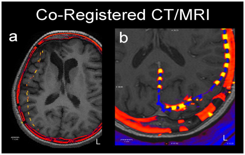
Two examples of how electrodes (yellow) shift in axial slices of post-operative CT (red) co-registered to pre-operative MRI (grey). a) (patient 4) A typical patient with a moderate (1 cm) medial shift of right frontal and parietal electrodes. b) (patient 1) A patient with occipital electrodes showing anterior shift of left occipital electrodes. These shifts reflect the underlying brain deformation.
It is therefore not a valid approach to evaluate the goodness of registration by comparing to intraoperative photographs in which electrodes necessarily conform to fixed in-grid distances. Intraoperative photography also has the limitation that it only applies to visually exposed areas where the convexity of the brain is usually low. Electrodes placed over inferior or medial cortical areas are usually slid into place through burr holes, and thus are not visible during surgery. In particular, the electrode shift may be large in areas where the cortex is highly warped, e.g., occipital pole, temporal pole, and inferior temporal gyrus, where intraoperative photography is usually unavailable. Beyond its theoretical limitations and spatial distortions, estimating the on-cortex locations of electrodes from photographs is a non-trivial exercise (Dalal et al. 2008). This physical deformation of the brain creates a problem for researchers and clinicians, as the cortical locations of the electrodes, and thus the actual location of the electrophysiologic activity recorded from the cortical surface, are not immediately clear. Although past researchers have provided techniques to correct for brain shift, and register the electrodes onto the pre-implant cortical surface, i.e., the cortical surface as it appears on the pre-implant MRI in order to minimize the uncertainty about the origin of electrophysiologic potentials generated in the brain (Hermes et al. 2010; Dykstra et al. 2012), here we address this problem in a completely novel manner by taking the geometry of the disk electrodes from the CT into account.
1.2 Formalization of the problem
As introduced above, there have been several approaches to addressing the problem of localizing postoperative electrodes using different input image modalities. However, we are unaware of a formal framework to understand and assess these methods. This electrode registration problem can be formalized as a weak form of the problem to determine the deformation of the cortex due to electrode implantation. The following discourse is intended to formalize the electrode registration problem.
Suppose that the pre-implant cortical surface, denoted by C, is deformed into C′ by some isometry s: C → C′ with some anatomical landmarks preserving constraints (Figure 2). The problem of determining this deformation amounts to solving for the map s given C and C′. Because the electrodes are implanted subdurally, they rest on the pial surface over the cortex, and we can denote their positions as E on the pre-implant surface C and E′ = s(E) on the post-implant surface C′, i.e. E ⊂ C and E′ ⊂ C′. This electrode registration problem amounts to solving for s−1 restricted to E, given E′ and C. Solving for C′ from E′ and C will yield a similarly desirable result as either pair of E and C or E′ and C′ will define the electrodes’ locations in respect to the cortex. This will require solving the full deformation problem.
Figure 2.
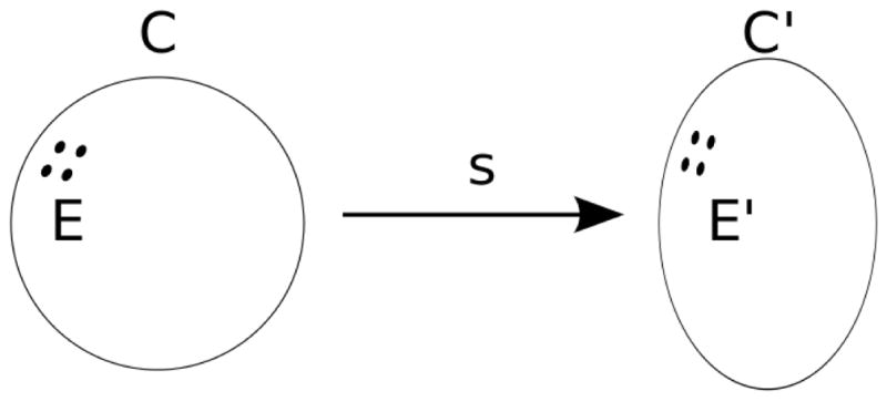
An S2 manifold C deforms into another S2 manifold C′ by homeomorphism s. electrodes E are mapped to E′ by s.
The electrode registration problem is a weak form of the deformation problem in the sense that if we can solve for s (or equivalently, s−1), then in particular, we can trivially obtain the electrode locations E from E = s−1(E′). This formalization is rather flexible: the aforementioned anatomical landmark preserving constraint on deformation s can be point-based or spline-based.
This simple formalization is already useful in re-evaluating the initial practice of testing a registration method by comparing it to intraoperative photography. Suppose we register a rectangular electrode grid; the in-grid distances between electrodes would be fixed according to grid configuration in the post-implant CT and also in the intraoperative photographs. But s−1 is only guaranteed to preserve in-cortex distance, not in-grid distance (the electrode grid is a manifold that intersects with C′ at E′ but generally not a part of C′) so it is generally false that E = s−1(E′) would conform to the same in-grid distances as E′ does.
The formalization suggests a way to quantitatively evaluate registration results, and thus registration methods. Specifically, obtaining the solution to the full deformation map s−1, will yield s−1 restricted to E′. Recovering s−1 restricted to E′ given E′ and C is a challenging task because the available information is extremely limited (E′, being a point set, has very little structure). Such an evaluation dataset can be constructed by incorporating post-implant MRI. It is possible to estimate the deformation map s by using FreeSurfer’s spherical map or other brain warping methods to connect the reconstructions of pre-implant cortex and post-implant cortex. Because subdural electrodes are implanted based on the clinical needs of the patient, one interesting option to explore further for inter-subject comparisons is to use FreeSurfer’s spherical map as the constraint (Fischl et al. 1999a, b).
2.1 Evaluation of Nonlinear Registration using Simulated Data
One of the most salient features in a post-implant CT is the disk-like geometry of electrodes (Figure 3). Instead of modeling electrodes as points, as in previously published methods, here the electrodes are modeled as disks with no extent, i.e. each electrode is specified by its center (a point) and orientation (a vector). Thus we have {ne f or e ∈ E} in addition to E′ and C and assuming good contact of the electrodes with the cortex, the disk orientations are the surface normals of C′ at E′. With the knowledge of the surface normals at E′, it is possible to estimate the deformation s by assuming that the deformation is purely compressive along the normals, and there is no shear within the grid perpendicular to the surface normals. Therefore to recover s−1 restricted to E′, we project each electrode e to the intersection of a line along its orientation ne and C. In order to evaluate the accuracy of surface-normal estimates to electrodes, we first generated simulated electrodes of known radius, thickness, and orientation.
Figure 3.
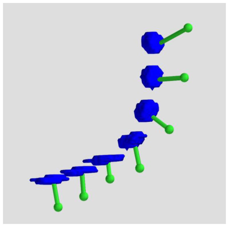
3D rendered ECoG electrodes from a CT scan. The electrodes as imaged in high resolution CT exhibit disk-like geometry as they progressively wrap around the cortex (blue: electrodes, green: translation to the dura).
2.1 Methods
1000 cylinders of uniformly random orientations were generated using custom-written python packages and visualized with MayaVi. Cylinders were generated with a radius of 2.5 mm (± 0.1 mm uniform random noise) and a thickness of 2.5 mm (± .5 mm uniform random noise). Uniform random noise was added to these parameters to approximate the variable boundaries of In Vivo electrodes on a thresholded CT image. After generation, cylinders were digitized into voxels that varied systematically in sampling density from .2 × .2 × .2 mm to 1.5 × 1.5 × 1.5 mm. Three techniques were developed and tested with simulations to estimate the orientation of a cylinder relative to ground-truth: (a) Best-Fitting Plane, (b) Random Sample Consensus and (c) Principal Axis.
The Best-Fitting Plane algorithm finds the plane that best fits all segmented electrode voxels.
Random Sample Consensus (RANSAC) is an iterative stochastic algorithm that tries to identify a plane that can explain most, instead of all of the segmented electrode voxels. In order to avoid fitting a plane to the voxels inside the segmented electrode cylinder, we hollowed out the electrode segments before running RANSAC. On a cylinder with large radius-to-height ratio, it should identify either the top cap or the bottom cap.
The Principal Axis method treats a segmented electrode as a solid object of uniform density. The moment of inertia matrix is calculated by summing the moment of inertia of each constituent voxel with respect to the center of mass of the electrode. Analysis has revealed that for a cylinder where the radius-to-height ratio is larger than , the principal axis with the largest moment of inertia is along the cylinder’s longitudinal axis.
Angular displacement values were calculated for each iteration as the difference between the estimated orientation relative to the true orientation for each of the three methods (Figure 4). This approach yielded 1000 angular displacement values for each method. Distributions of angular displacement were compared using Kruskal-Wallis Tests (non-parametric one-way ANOVA) and follow-up Wilcoxon rank order tests (non-parametric t-tests).
Figure 4.
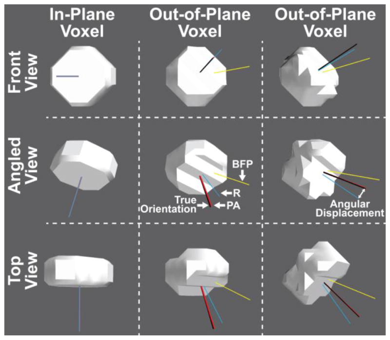
Simulated electrodes (radius = 2.5 mm, thickness = 2.5 mm) digitized in the same anisotropic CT voxels (0.5 × 0.5 × 0.5 mm resolution), but at different orientations to the voxel plane (left column in-plane, center and right columns out-of-plane) and shown from different angles (rows). The true orientation of the electrode is represented by the black line and the three colored lines represent the orientation calculated by each of the three measures: Best-Fitting Plane (BFP; yellow), RANSAC (R; blue), and Principal Axis (PA; red). The angular displacement between the true and calculated electrode orientation increases when the orientation of the electrode does not match the voxel slice orientation. Nevertheless, the Principal Axis method significantly outperformed the other two measures regardless of electrode orientation. Some overlapping axes are not visible.
2.2 Results
Because the true orientation of any implanted electrode is not known, its orientation must be estimated from the post-op CT image. Three techniques were developed and tested with simulations to estimate the orientation of a stimulated electrode from CT: Best-Fitting Plane, RANSAC, and Principal Axis. 1000 disks of uniformly random orientations were generated and these three proposed analysis techniques were applied to estimate their orientations for comparison with their true orientations. As the calculated orientation of the stimulated electrode could be affected by the orientation of the voxels or slices after digitization of the stimulated electrode into voxels (Figure 4), the 1000 generated cylinders were drawn from uniformly random generated orientations to yield a sample of electrodes representative of real-world constraints.
Figure 5 shows the histograms of the inner product of estimated and true orientations for each of these methods. At 0.2 × 0.2 × 0.2 mm voxel resolution, Principal Axis showed the lowest angular displacement relative to the true disk orientation (median angular displacement of 0.17 degrees), RANSAC the second best (median angular displacement of 5.60 degrees), and Best-Fitting Plane the worst (median angular displacement of 29.88 degrees), with differences between these distributions confirmed using Kruskal-Wallis Tests (H(2) = 2320.1, p < .0001). Follow-up tests using the Wilcoxon Method confirmed the significant differences between these methods in a pairwise fashion: Principal Axis greater than RANSAC (z = 38.4, p < .0001), Principal axis greater than Best-Fitting Plane (z = 38.7, p < .0001), and RANSAC greater than Best-Fitting Plane (z = 27.4, p < .0001).
Figure 5.
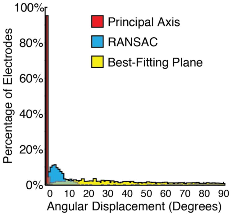
Histograms showing the results of the accuracy in degrees between the true orientation and the orientations estimated by the three proposed methods. The Principal Axis method shows the lowest angular displacement highlighting it as the most robust and reliable method.
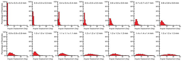
As poor anisotropic resolution of the CT will limit the amount of shape information present in the digitized voxels, we separately evaluated the impact of voxel size on angular disparity for the Principal Axis method. 1000 disks of uniformly random generated orientations were created at 14 isotropic voxel resolutions, varying linearly from .2 × .2 × .2 mm to 1.5 × 1.5 × 1.5 mm in .1 mm intervals. Figure 6 shows the histograms of the inner product of the true orientations relative to the Principal Axis estimated orientations. Table 1 reports the median, min, and max angular displacements at each of these voxel resolutions and associated cubic volume. Angular displacement increased as a function of voxel size and showed a linear and positive relationship with voxel volume (such that increased voxel volume correlated with increased angular displacement), r = 0.963, t(12) = 12.46 p < .0001.
Figure 6.
Histograms showing the results of the accuracy in degrees between the true orientation and the orientations estimated by Principal Axis at voxel resolutions varying from 0.2 mm isotropic to 1.5 mm isotropic. Mean accuracy decreases linearly with cubic voxel size.
Table 1.
Angular displacement as a function of voxel size
| Voxel Resolution (mm) | Volume (mm^3) | Mean (degrees) | Min (degrees) | Max (degrees) |
|---|---|---|---|---|
| 0.2 × 0.2 × 0.2 | 0.01 | 0.2 | 0.0 | 2.1 |
| 0.3 × 0.3 × 0.3 | 0.03 | 0.5 | 0.0 | 3.9 |
| 0.4 × 0.4 × 0.4 | 0.06 | 1.0 | 0.0 | 6.7 |
| 0.5 × 0.5 × 0.5 | 0.13 | 1.6 | 0.0 | 11.1 |
| 0.6 × 0.6 × 0.6 | 0.22 | 2.4 | 0.1 | 14.4 |
| 0.7 × 0.7 × 0.7 | 0.34 | 3.1 | 0.0 | 20.1 |
| 0.8 × 0.8 × 0.8 | 0.51 | 3.9 | 0.0 | 17.5 |
| 0.9 × 0.9 × 0.9 | 0.73 | 5.9 | 0.4 | 18.2 |
| 1.0 × 1.0 × 1.0 | 1.00 | 4.4 | 0.1 | 19.3 |
| 1.1 × 1.1 × 1.1 | 1.33 | 7.8 | 0.1 | 29.0 |
| 1.2 × 1.2 × 1.2 | 1.73 | 11.3 | 0.5 | 28.4 |
| 1.3 × 1.3 × 1.3 | 2.20 | 11.3 | 0.5 | 89.6 |
| 1.4 × 1.4 × 1.4 | 2.74 | 11.0 | 0.5 | 52.9 |
| 1.5 × 1.5 × 1.5 | 3.38 | 14.1 | 0.3 | 33.6 |
3.1 In Vivo Clinical Studies
Artificially generated electrodes reflect the best-case scenario for the application of these methods. Conversely, In Vivo electrodes will vary in their size and specific shape due to signal dropout, merged electrodes, and contact with signal artifacts including the skull, wires, and staples. As our in silico simulations revealed Principal Axis to be the best a priori method for establishing the tangent vector of electrodes, here we applied this method to clinically acquired post-operative CT images to evaluate their clinical efficacy relative to manually adjusted electrode placements. To provide a metric relative to other studies, we additionally localized electrodes using the nearest-neighbor approach, relative to manually adjusted electrode placements.
3.2 Methods
CT and MRI scans from 10 epilepsy surgery patients were studied as they became available. Inclusion and exclusion criteria were based on clinical grounds, according to the needs of the patient. Pre-operative structural MRI scans were obtained on a GE 3T scanner with 512 × 512 in-plane resolution using a T1 pulse sequence. Post-operative CT scans were obtained on different clinical scanners with various resolutions; the clinical and imaging characteristics of the patients are displayed in Table 2. MRI and CT images were registered using the mutual information methods contained in SPM8 (Viola & Wells, 1997; Penny et al. 2006). No reslicing or resampling of the CT was used.
Table 2.
Demographic, clinical and imaging characteristics of the patients.
| Pt. | Gender | Age | Diag. | MRI Status | # Elect. | Split Elect. | Manual Elect. | Areas | CT Voxel Resolution (mm) | Volume (mm^3) |
|---|---|---|---|---|---|---|---|---|---|---|
| 1 | F | 27 | L TLE | L med t scler | 136 | 17 | 3 | L fpto | 0.453 × 0.453 × 0.600 | 0.137 |
| 2 | F | 21 | L TLE | normal | 64 | 2 | 1 | L fpt | 0.409 × 0.409 × 1.000 | 0.167 |
| 3 | M | 28 | R TLE | B t enceph | 64 | 8 | 0 | R fpot | 0.434 × 0.434 × 0.900 | 0.170 |
| 4 | F | 15 | R TLE | normal | 96 | 10 | 0 | R fpt | 0.424 × 0.424 × 1.000 | 0.180 |
| 5 | F | 9 | L TLE | L med t scler | 122 | 7 | 0 | L fpt | 0.449 × 0.449 × 1.000 | 0.202 |
| 6 | F | 46 | L TLE | L t cavernoma | 54 | 10 | 0 | L fpt | 0.488 × 0.488 × 1.000 | 0.238 |
| 7 | F | 16 | R o sz | R f encephala | 144 | 12 | 10 | R ftp | 0.502 × 0.502 × 1.000 | 0.252 |
| 8 | F | 24 | R TLE | R polymicrog | 104 | 12 | 0 | R fpt | 0.503 × 0.503 × 1.000 | 0.253 |
| 9 | M | 15 | L f sz | L t lesion | 136 | 8 | 36 | L fpt | 0.512 × 0.512 × 1.500 | 0.393 |
| 10 | M | 30 | L TLE | normal | 72 | 9 | 0 | L ft | 1.000 × 1.000 × 1.000 | 1.000 |
Using one of the proposed estimation techniques, we obtained {ne} and E′. The pre-implant cortical surface C was extracted from the MRI using FreeSurfer. Due to the fixed lattice arrangement of electrodes in an electrode grid, some electrodes were inadvertently placed onto blood vessels or lesions, and were therefore out of contact with C′ (Figure 7). To avoid registering electrodes into sulci, instead of strictly following the discussion of using cortical surface C and C′, in practice, we registered E′ onto the pre-implant dura surface D. The pre-implant dura surface D was approximated by a morphological closing operation on C′, with a spherical element of some suitable radius (Dykstra et al. 2012; Schaer et al. 2008). We generated the dura surface with custom scripts that are available as part of the included registration program at https://github.com/towle-lab/electrode-registration-app which utilized common FreeSurfer tools including the mris_fill and make_outer_surface functions. The diameter should be somewhat larger than the width of a typical sulcus; we used 15mm following Schaer et al. (2008).
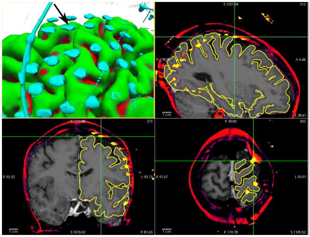
Figure 7.
(patient 1) An electrode (marked with cursors and arrow) segmented from CT, and registered to the presurgical MRI, floating in space over a sulcus.
After registration and generation of the dural surface, the electrode voxels were segmented from the CT with thresholding by intensity (Hunter et al. 2005); voxel intensity values used to segregate electrodes from other signals on the CT were set initially to 3200 and then were reduced until the majority of electrodes were visualized with their shape information maintained. Clusters of contiguous voxels above this intensity threshold value were then subject to inclusion only if they were within 25 mm of the dura surface and displayed a volume of 5 mm3, to exclude remnant skull, wires, and other artifacts. Any artifacts that survived these correction procedures were then removed from visualization. As electrodes overlapping with one another or that were merged with the skull are comprised of a single contiguous set of voxels that lacks disk shape information, we excluded these electrodes from analyses (see Table 2). In addition, as setting a single voxel intensity threshold was not optimal for all areas due to signal dropout, not all electrodes were always located in a single pass and had to be added in manually or located at a second pass with a lower threshold; for simplicity we excluded manually added electrodes from the present analyses (see Table 2).
We then registered electrodes to the dura surface using three methods: (a) Principal Axis, (b) Nearest Neighbor Approximation, and (c) Manual Electrode Placement.
Principal Axis, described in our simulation studies, was shown to be the best a priori method for establishing the tangent vector of electrodes and here we test its performance in real-world settings. Estimated electrode position on the dura surface was identified by contact with the projection of the tangent vector from the electrode.
Nearest Neighbor Approximation, in which the closest dura point relative to an electrode voxel in Cartesian space (equivalent to modeling the deformation being minimal in terms of distance), was used as a comparative measure.
Manual Electrode Placement, in which the spatial positions of electrodes were manually adjusted using known electrode geometry, relative positions of electrodes on strips and grids, as well as intraoperative photography (when available), was completed by one of the authors (DB) and used as the closest measure to ground truth available for comparison with the other two methods.
The registered images were displayed with the multi-image capabilities of FreeSurfer (Fischl et al. 2004; Segonne et al. 2004, 2007).
For each of the 10 patients we calculated the difference between Principal Axis and Manual Electrode Placement, Nearest Neighbor Approximation and Manual Electrode Placement, as well as the difference in errors between Principal Axis and Nearest Neighbor Approximation ((Principal Axis - Manual)- (Nearest Neighbor - Manual)). Accuracy between the two measures was compared using paired two-tailed t-tests.
3.3 Results
Accuracy for the Principal Axis and Nearest Neighbor Approximations were compared relative to Manual Electrode Placement. Registration errors between these two measures relative to Manual Electrode Placement for each of the 10 patients are presented in Table 3. Across these patients, Principal Axis resulted in significantly less registration error (mean = 0.4 mm, SD = 0.8 mm) than that of Nearest Neighbor Approximation (mean = 1.6 mm, SD = 0.9 mm), t(9) = 3.95, p = .003. At the individual subject level, 9 out of 10 patients showed significantly better registration accuracy with Principal Axis compared to Nearest Neighbor Approximation (see Table 3); the patient who experienced no difference in registration accuracy between the two methods had the lowest CT resolution among the group (Patient 10: 1.0 × 1.0 × 1.0 mm).
Table 3.
Individual subjects’ registration accuracy using the Principal Axis and Nearest Neighbor Approximation techniques. Electrode displacement is additionally reported as length of the vector between pre- and post-registration of electrodes as an estimate of average brain shift.
| Pt. | Principal Axis - Manual (mm) Mean (min-max) | Nearest Neighbor - Manual (mm) Mean (min-max) | Principal Axis vs. Nearest Neighbor Statistics | Electrode displacement (mm) Mean (min-max) |
|---|---|---|---|---|
| 1 | 0.0 (0.0 – 0.0) | 1.1 (0.0 – 10.7) | t(115) = 8.1 p < .0001) | 3.9 (0.2 – 14.7) |
| 2 | 0.2 (0.0 – 3.8) | 1.6 (0.0 – 5.4) | t(60) = 8.4 p < .0001) | 5.0 (0.3 – 12.4) |
| 3 | 0.6 (0.0 – 13.2) | 4.0 (0.0 – 15.5) | t(55) = 5.9 p < .0001) | 8.0 (0.0 – 14.3) |
| 4 | 0.1 (0.0 – 2.5) | 1.1 (0.0 – 5.6) | t(85) = 10.7 p < .0001) | 4.6 (0.1 – 10.8) |
| 5 | 0.0 (0.0 – 0.0) | 0.9 (0.0 – 11.9) | t(114) = 7.3 p < .0001) | 3.4 (0.2 – 12.7) |
| 6 | 0.0 (0.0 – 0.0) | 1.0 (0.0 – 3.2) | t(43) = 8.5 p < .0001) | 3.8 (0.2 – 7.8) |
| 7 | 0.2 (0.0 – 5.9) | 1.7 (0.0 – 7.4) | t(121) = 8.3 p < .0001) | 6.0 (0.2 – 14.2) |
| 8 | 0.0 (0.0 – 0.0) | 1.6 (0.0 – 6.2) | t(91) = 12.7 p < .0001) | 5.1 (0.1 – 10.5) |
| 9 | 0.6 (0.0 – 10.2) | 1.3 (0.0 – 3.5) | t(91) = 3.2 p < .0001) | 6.3 (1.0 – 11.6) |
| 10 | 2.6 (0.0 – 25.9) | 2.1 (0.0 – 6.1) | t(62) = 1.0 p = .309) | 6.1 (1.4 – 13.0) |
In order to further explore the poor performance of the Principal Axis technique applied to Patient 10 we calculated this subjects’ predicted error based on the simulation data. Table 1 reports that a 1.0 × 1.0 × 1.0 mm CT resolution engenders a maximum angular displacement of 19.3 degrees. Extrapolating from this worst case scenario and using Patient 10’s electrode displacement value of 6.1 mm we can calculate ([tan(angular displacement) * electrode displacement]) an average linear registration error of 2.14 mm, slightly under the observed average error of 2.6 mm.
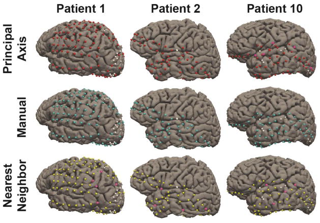
Figure 8 shows the electrodes from three representative subjects (including Patient 10) registered using these three different approaches, and highlights that small deviations in registration accuracy can lead to mislocalization of electrodes onto incorrect gyri. In order visualize the distribution of mislocalization errors made by the two techniques, we additionally include histograms for the 10 patients, reflecting the difference in registration accuracy between Nearest Neighbor and Principal Axis (Figure 9).
Figure 8.
Electrodes registered to the cortical surface for three representative patients. Electrodes registered using Principal Axis are marked red, Manually marked cyan, and Nearest Neighbor Approximation marked yellow. White electrodes denote electrodes not registered due to poor signal quality or merged contacts. Pink electrodes highlight errors in registration that led to the placement onto an incorrect gyral surface.
Figure 9.
Individual electrode histograms reflecting the difference in mislocalization errors in mm between Nearest Neighbor and Principal Axis methods, presented for each of the 10 patients. Positive values on the x-axis reflect the number of individual electrodes that were better localized with Principal Axis, and negative numbers on the x-axis reflect the number of individual electrodes that were better localized with Nearest Neighbor.
4.1 Discussion
Here we describe and test a new approach to spatially adjust 3D MRI images so that subdural electrode locations from a CT will be translated to the physiologically appropriate locations on the post-surgical surface of the brain. This method enables the accurate registration of intracranial electrodes, enabling more accurate analyses of electrophysiologic findings over the cortex. Specifically, using computational simulations to model electrodes as disks we found our Principal Axis method more reliable and robust against noisy segmented voxels. Applying this method to clinically acquired intracranial electrodes extracted from CT images, we found the Principal Axis method predicted the pre-implant spatial location of electrodes relative to the surface of the brain with remarkable accuracy, exceeding the performance of Nearest Neighbor approaches. Although registration validity was not confirmed with cortical stimulation mapping, ECoG gamma localization revealed that electrodes associated with specific cortical functions were located on the appropriate gyri, as determined by the anatomic gyral database within FreeSurfer (Desikan et al. 2006; Fischl et al. 2004).
Our simulation study compared three computational methods to identify the tangent vector to a cylinder resampled into common CT resolutions. The Principal Axis method, in which the moment of inertia of each constituent voxel within a segmented electrode is used to estimate the tangent vector, was the most reliable method in simulations. Indeed, this method indicated little angular disparity even at low image resolutions (large voxel size). Of note, however, at very small voxel sizes (less than 0.1 × 0.1 × 0.1 mm) each of the three proposed methods performed well in our simulations. However, using realistic voxel sizes ranging from 0.2 × 0.2 × 0.2 mm to 1.5 × 1.5 × 1.5 mm, Principal Axis demonstrated the least error in calculating the tangent vector when the electrode did not match the in-plane slicing of the voxels and with increased voxel size. Although smaller voxels will provide increased resolution of electrodes’ geometry, the advantage of high-resolution scans must be balanced with the dangers of excess radiation (Berrington de González et al. 2009).
The method described by Hermes et al. (2010) is similarly resistant to the problem of increased angular disparity with increased voxel size, and is the most similar to our Principal Axis method in that it also tries to make use of the information from the surface normal. However it differs from our method in how surface normals are estimated; electrodes are modeled as points and the normal is estimated from multiple nearby electrodes’ locations. Although, our method works well for electrodes in a single-row strip (Figure 3), estimating normals from overlapping sets of points would effectively produce smooth normals across an electrode grid. A combination of these two approaches might produce superior results.
In parallel to our simulation studies, Principal Axis reliably localized electrodes segmented from post-operatively acquired CT image relative to Nearest Neighbor electrode localization procedures in 9 out of 10 patients. Patient 10, in whom there was no difference between the two registration techniques, showed the poorest CT resolution which limited our application’s ability to extract robust shape information from the segmented voxels. Principal Axis proved beneficial to all other patients with better CT resolutions (<1 mm3 volumes), indicating this as the upper threshold in a practical sense. Failure to use the Principal Axis approach (and its use with low resolution CT images) resulted in mislocalization of several electrodes onto incorrect cortical gyri even in instances where the misregistration was small.
As both voxel size and the electrode orientation relative to voxel plane can lead to angular displacement using the Principal Axis method, the effect of this offset depends on the extent of brain shift at each electrode contact (with increased brain shift resulting in reduced localization accuracy approximated by the function [tan(angular displacement) * brain shift distance]). Table 3 reported the minimum, maximum, and mean displacement distance of electrodes, with maximum values of approximately 14 mm across patients. Utilization of this technique for patients with a large number of electrodes over different brain regions demonstrated the logical case that regions with increased brain shift will show worse registration accuracy due to the probabilistic distribution of the estimated tangent vector. In specific, if an electrode is only mildly displaced from pre-implant cortex, then little difference will be observed across registration techniques, even at low CT resolutions.
Past methods have also achieved clinically acceptable levels of registration accuracy using alternative procedures, including post-operative MRIs as opposed to CTs. In a method proposed by Yang and colleagues (2012), electrodes were registered along the rays originating from a fixed central point, equivalent to modeling the deformation as compressing towards the chosen fixed point. While this technique was efficient in localizing electrodes in a lateral grid, this modeling approach is ineffective for strips of electrodes and in areas of high curvature, including the temporal and occipital poles among others. In addition, as limits to this method, a post-operative MRI is not available in all instances for all patients and as electrodes produce significant artifact on the MRI, the points of contact on individual gyri could not be unambiguously identified. Nevertheless, as this technique made efficient use of relative information about the spatial positions of neighboring electrodes, some combination of techniques may prove efficient. Of critical note, even though a single method may prove adequate in providing an average mislocalization error of approximately 1 mm, a small number of electrodes will often exceed this threshold raising the possibility they may actually be localized on different cortical gyri which may affect clinical care. Indeed, in the present data, 220 out of 847 (26.0%) of the electrodes localized with the Nearest Neighbor approach were mislocalized with an error greater than 2 mm, and in extreme cases electrodes can be mislocalized with an error exceeding 5 mm (36 out of 847 electrodes, 4.3%), highlighting the need for continued improvement in registration accuracy.
When implemented in a practical clinical context, Principal Axis yielded reliable registration for the majority of electrodes across patients with acceptable CT resolutions. Critically, our method is subject to failure when electrodes cannot be segmented away from overlapping electrodes, nearby wires, or skull artifacts, leading to insufficiently well-defined shape information for accurate estimation of the electrode orientation. Given this, our present application does not account for the signal dropout that occurs in some regions, which is compounded by our use of a single threshold value to segment skull and artifacts from electrodes, limiting our ability to fully maximize the extent, and thus the shape, of electrodes in all instances. In the present data, electrodes that were overlapping or merged with voxels from CT artifacts accounted for 95 out of 992 total electrodes across the present 10 patients. Improving the ability to segment these merged voxels while preserving the shape information of the individual electrodes (along with the introduction of an adaptive thresholding procedure that utilizes known size of the electrodes) will provide a significant enhancement to the present protocol and is a goal we are actively pursuing. Without these enhancements, these small numbers of electrodes are best treated by nearest-neighbor approximation. A selection of both disk-based and point-based methods is included in in our interactive registration program (available at https://github.com/towle-lab/electrode-registration-app).
With regard to the achievable spatial accuracy of ECoG electrode registration, there may be some ceiling due to the inherent limitation of ECoG technology. Unlike microelectrode arrays that have pin electrodes, ECoG grids’ flat electrodes do not insert into the cortex and are usually sutured to the dura by the edges of a grid. In the clinical setting, one can sometimes observe the artifacts in recorded data due to large head movements during a recording, or due to pulse-related movement of some electrodes, presumably because the electrodes’ contact with the brain is disturbed. Over time, the position of the electrodes changes as well. There has been a quantitative report on the displacement of electrodes between implant and explant (LaViolette et al. 2013). Another option for accuracy validation is through functional ECoG recordings. When there are electrodes serendipitously implanted between two well-established, functionally distinguishable regions like the central sulcus, which sits between sensory and motor areas, we could use the functional selectivity to determine whether the registration is correct per gyrus. Over some highly warped areas, where different registration methods select different gyri assignments, this functional test may be used to compare methods.
In addition to facilitating electrode localization, the present software package may also be useful for estimating brain shift as a function of time. In terms of clinical relevance, brain shift, particularly when it distorts the midline structures, can be an early warning sign for possible infarction, edema, and eventually, life-threatening herniation. This can happen quickly, and can become a medical emergency. Our post-op CTs are taken immediately after surgery, and reveal a substantial volume of subdural fluid can accumulate rapidly. The distance between the electrodes as imaged in CT, and their corresponding registered locations on the dura could be an objective and quantitative proxy for measuring brain shift. If subsequent CTs are taken, this value could be recalculated to see if there is an alarming progression of this process.
In sum, these data from both simulated and clinical acquired intracranial electrodes demonstrate that our Principal Axis method can reliably estimate the orientations of the electrodes from their CT imagery. Because intraoperative photography is ill-suited for establishing true on-cortex locations of electrodes after brain shift, and as areas of high curvature prevent the cortex from being modeled as a planar surface, the present method provides a useful model for estimating the true location of intracranial electrodes post-implantation.
Highlights.
A formalization of the electrode registration problem is presented.
Electrodes are modeled geometrically as disks to determine their orientations.
A new validation method for electrode registration accuracy is proposed.
Acknowledgments
This study was supported in part supported by NIH R01 NS40514, NIH K99 DC013828, The Brain Research Foundation and The Susman & Asher Foundation. We are grateful to G. Kavya Minama-Reddy for her contributions to this work.
Footnotes
Publisher's Disclaimer: This is a PDF file of an unedited manuscript that has been accepted for publication. As a service to our customers we are providing this early version of the manuscript. The manuscript will undergo copyediting, typesetting, and review of the resulting proof before it is published in its final citable form. Please note that during the production process errors may be discovered which could affect the content, and all legal disclaimers that apply to the journal pertain.
References
- Berrington de González A, Mahesh M, Kim KP, Bhargavan M, Lewis R, Mettler F, Land C. Projected cancer risks from computed tomographic scans performed in the United States in 2007. Arch Intern Med. 2009;169(22):2071–2077. doi: 10.1001/archinternmed.2009.440. [DOI] [PMC free article] [PubMed] [Google Scholar]
- Dalal SS, Edwards E, Kirsch HE, Barbaro NM, Knight RT, Nagarajan SS. Localization of neurosurgically implanted electrodes via photograph–MRI–radiograph coregistration. J Neurosci Meth. 2008;174(1):106–115. doi: 10.1016/j.jneumeth.2008.06.02. [DOI] [PMC free article] [PubMed] [Google Scholar]
- Desikan RS, Segonne F, Fischl B, Quinn BT, Dickerson BC, Blacker D, Buckner RL, Dale AM, Maguire RP, Hyman BT, Albert MS, Killiany RJ. An automated labeling system for subdividing the human cerebral cortex on MRI scans into gyral based regions of interest. NeuroImage. 2006;31:968–980. doi: 10.1016/j.neuroimage.2006.01.021. [DOI] [PubMed] [Google Scholar]
- Dykstra AR, Chan AM, Quinn BT, Zepeda R, Keller CJ, Cormier J, Madsen JR, Eskandar EN, Cash SS. Individualized localization and cortical surface-based registration of intracranial electrodes. NeuroImage. 2012;59(4):3563–3570. doi: 10.1016/j.neuroimage.2011.11.046. [DOI] [PMC free article] [PubMed] [Google Scholar]
- Elias WJ, Fu KM, Frysinger RC. Cortical and subcortical brain shift during stereotaxic procedures. J Neurosurg. 2007;107:983–988. doi: 10.3171/JNS-07/11/0983. [DOI] [PubMed] [Google Scholar]
- Engel AK, Moll CK, Fried I, Ojemann GA. Invasive recordings from the human brain: clinical insights and beyond. Nat Rev Neurosci. 2005;6(1):35–47. doi: 10.1038/nrn1585. [DOI] [PubMed] [Google Scholar]
- Fischl B, Liu A, Dale AM. Automated manifold surgery: constructing geometrically accurate and topologically correct models of the human cerebral cortex. IEEE Trans Med Imag. 2001;20:70–80. doi: 10.1109/42.906426. [DOI] [PubMed] [Google Scholar]
- Fischl B, Sereno MI, Dale AM. Cortical surface-based analysis. II: Inflation, flattening, and a surface-based coordinate system. NeuroImage. 1999a;9:195–207. doi: 10.1006/nimg.1998.0396. [DOI] [PubMed] [Google Scholar]
- Fischl B, Sereno MI, Tootell RB, Dale AM. High-resolution intersubject averaging and a coordinate system for the cortical surface. Hum Brain Map. 1999b;8:272–284. doi: 10.1002/(SICI)1097-0193(1999)8:4<272::AID-HBM10>3.0.CO;2-4. [DOI] [PMC free article] [PubMed] [Google Scholar]
- Fischl B, van der Kouwe A, Destrieux C, Halgren E, Segonne F, Salat DH, Busa E, Seidman LJ, Goldstein J, Kennedy D, Caviness V, Makris N, Rosen B, Dale AM. Automatically parcellating the human cerebral cortex. Cereb Cortex. 2004;14:11–22. doi: 10.1093/cercor/bhg087. [DOI] [PubMed] [Google Scholar]
- Grzeszczuk R, Tan KK, Levin DN, Pelizzari CA, Hu X, Chen GTY, Beck RN, Chen CT, Cooper M, Milton J, Spire JP, Towle VL, Dohrmann GJ, Erickson RK. Retrospective fusion of radiographic and MR data for localization of subdural electrodes. J Comp Assisted Tomogr. 1992;16:764–773. doi: 10.1097/00004728-199209000-00018. [DOI] [PubMed] [Google Scholar]
- Hermes DK, Miller J, Noordmans HJ, Vansteensel MJ, Ramsey NF. Automated electrocorticographic electrode localization on individually rendered brain surfaces. J Neurosci Meth. 2010;185(2):293–298. doi: 10.1016/j.jneumeth.2009.10.005. [DOI] [PubMed] [Google Scholar]
- Hunter JD, Hanan DM, Singer BF, Shaikh S, Brubaker KA, Hecox KE, Towle VL. Locating chronically implanted subdural electrodes using surface reconstruction. Clin Neurophysiol. 2005;116:1984–1987. doi: 10.1016/j.clinph.2005.03.027. [DOI] [PubMed] [Google Scholar]
- LaViolette PS, Hoyt A, Rand SD, Schmainda KM, Mueller WM. 3D visualization of subdural electrode shift as measured at craniotomy reopening. Epilepsy Res. 2013;94(1–2):102–109. doi: 10.1016/j.eplepsyres.2011.01.011. [DOI] [PMC free article] [PubMed] [Google Scholar]
- Morris K, O’Brien TJ, Cook MJ, Murphy M, Bowden SC. A computer-generated stereotactic “virtual subdural grid” to guide resective epilepsy surgery. Am J Neuroradiol. 2004;25:77–83. [PMC free article] [PubMed] [Google Scholar]
- O’Shea JP, Wells WM, III, Golby AJ. Using surface normals to localize subdural intracranial electrodes placed during neurosurgery. Proc IEEE Int Symp Biomed Imaging; 2006. pp. 331–334. [Google Scholar]
- Penny W, Friston K, Ashburner JS, … Nichols T, editors. Statistical Parametric Mapping: The Analysis of Functional Brain Images. 1. Elsevier; 2006. [Google Scholar]
- Pieper S, Halle M, Kikinis R. 3D SLICER. Proc IEEE Int Symp Biomed Imaging; Apr; 2004. pp. 632–5. [Google Scholar]
- Pieters TA, Conner CR, Tandon N. Recursive grid partitioning on a cortical surface model: An optimized technique for the localization of implanted subdural electrodes. J Neurosurg. 2013;118:1086–1097. doi: 10.3171/2013.2.JNS121450. [DOI] [PubMed] [Google Scholar]
- Rosenbaum TJ, Laxer KD, Vessely M, Smith WB. Subdural electrodes for seizure focus localization. Neurosurgery. 1986;19:73–81. doi: 10.1227/00006123-198607000-00011. [DOI] [PubMed] [Google Scholar]
- Rutka JT, Otsubo H, Kitano S, Shirasawa A, Ochi A, Snead OC., 3rd Utility of digital camera-derived intraoperative images in the planning of epilepsy for children. Neurosurgery. 1999;45:1186–1191. doi: 10.1097/00006123-199911000-00033. [DOI] [PubMed] [Google Scholar]
- Schaer M, Cuadra MB, Tamarit L, Lazeyras F, Eliez S, Thiran J. A surface-based approach to quantify local cortical gyrification. Med Imag IEEE Transactions on. 2008;27(2):161, 170. doi: 10.1109/TMI.2007.903576. [DOI] [PubMed] [Google Scholar]
- Segonne F, Dale AM, Busa E, Glessner M, Salat D, Hahn HK, Fischl B. A hybrid approach to the skull stripping problem in MRI. NeuroImage. 2004;22:1060–1075. doi: 10.1016/j.neuroimage.2004.03.032. [DOI] [PubMed] [Google Scholar]
- Segonne F, Pacheco J, Fischl B. Geometrically accurate topology-correction of cortical surfaces using nonseparating loops. IEEE Trans Med Imag. 2007;26:518–529. doi: 10.1109/TMI.2006.887364. [DOI] [PubMed] [Google Scholar]
- Skninjan O, Nabavi A, Duncan J. Model-driven brain shift compensation. Med Image Anal. 2002;6:361–70. doi: 10.1016/s1361-8415(02)00062-2. [DOI] [PubMed] [Google Scholar]
- Spencer SS, Spencer DD, Williamson PD, Mattson R. Combined depth and subdural electrode investigation in uncontrolled epilepsy. Neurology. 1990;40:74–79. doi: 10.1212/wnl.40.1.74. [DOI] [PubMed] [Google Scholar]
- Tao JX, Hawes-Ebersole S, Baldwin M, Shah S, Erickson RK, Ebersole JS. The accuracy and reliability of 3D CT/MRI co-registration in planning epilepsy surgery. Clin Neurophysiol. 2009;120:748–753. doi: 10.1016/j.clinph.2009.02.002. [DOI] [PubMed] [Google Scholar]
- Thevenaz P, Unser M. Optimization of mutual information for multiresolution image registration. IEEE Trans Image Process. 2000;9:2083–2099. doi: 10.1109/83.887976. [DOI] [PubMed] [Google Scholar]
- Towle VL, Yoon HA, Castelle MC, Edgar JC, Biassou NM, Frim DM, Spire J-P, Kohrman MH. ECoG gamma activity during a language task: Differentiating expressive and receptive speech areas. Brain. 2008;131:2013–2027. doi: 10.1093/brain/awn147. [DOI] [PMC free article] [PubMed] [Google Scholar]
- Towle VL, Cohen S, Alperin N, Hoffmann K, Cogen P, Milton J, Grzesczcuk R, Pelizzari C, Syed I, Spire JP. Displaying electrocorticographic findings on gyral anatomy. Electroencephalogr Clin Neurophysiol. 1995;94:221–228. doi: 10.1016/0013-4694(95)98474-m. [DOI] [PubMed] [Google Scholar]
- van Veelen CW, Debets RM, van Huffelen AC, van Emde Boas W, Binnie CD, Storm van Leeuwen W, Velis DN, van Dieren A. Combined use of subdural and intracerebral electrodes in preoperative evaluation of epilepsy. Neurosurgery. 1990;26:3–101. doi: 10.1097/00006123-199001000-00013. [DOI] [PubMed] [Google Scholar]
- Viola P, Wells WM. Alignment by maximization of mutual information. Int J Comput Vis. 1997;24:137–154. [Google Scholar]
- Wellmer J, von Oertzen J, Schaller C, Urbach H, König R, Widman G, Dirk Van Roost D, Elger CE. Digital photography and 3D MRI-based multimodal imaging for individualized planning of resective neocortical epilepsy surgery. Epilepsia. 2002;43(12):1543–1550. doi: 10.1046/j.1528-1157.2002.30002.x. [DOI] [PubMed] [Google Scholar]
- Yang AI, Wang X, Doyle WK, Halgren E, Carlson C, Belcher TL, Cash SS, Devinsky O, Thesen T. Localization of dense intracranial electrode arrays using magnetic resonance imaging. NeuroImage. 2012;63(1):157–65. doi: 10.1016/j.neuroimage.2012.06.039. [DOI] [PMC free article] [PubMed] [Google Scholar]


