Abstract.
Optical-resolution photoacoustic microscopy (OR-PAM) offers label-free in vivo imaging with high spatial resolution by acoustically detecting optical absorption contrasts via the photoacoustic effect. We developed a compact handheld OR-PAM probe for fast photoacoustic imaging. Different from benchtop microscopes, the handheld probe provides flexibility in imaging various anatomical sites. Resembling a cup in size, the probe uses a two-axis water-immersible microelectromechanical system mirror to scan both the illuminating optical beam and resultant acoustic beam. The system performance was tested in vivo by imaging the capillary bed in a mouse ear and both the capillary bed and a mole on a human volunteer.
Keywords: photoacoustic handheld probe, optical-resolution photoacoustic microscopy, two-axis microelectromechanical system mirror, confocal scanning, human skin imaging
The American Cancer Society recommends regular examinations of skin lesions as the best way to find skin cancers early.1 Therefore, a noninvasive device that can easily scan the body would facilitate such routine examinations. Optical microscopy has excellent imaging contrast in soft tissue2 and has been miniaturized for clinical applications. For use in medical offices and clinics, handheld microscopes have been developed based on various optical imaging modalities.3–6 Compact confocal microscopy achieves fast imaging speed with high spatial resolution, but its shallow imaging depth (200 to ) limits its wide application.3,4 Optical coherence tomography-based probes exploit the optical contrast in backscattered light5,6 and are complementary to photoacoustic tomography (PAT), which shows the optical absorption contrast.
PAT is a hybrid imaging modality in which laser-generated ultrasound waves are used to obtain three-dimensional (3-D) images of soft tissue.7,8 A major implementation of PAT, optical-resolution photoacoustic microscopy (OR-PAM), provides optical absorption contrast with high resolution9 and has been proven capable of anatomical, chemical, functional, and metabolic imaging.10–15 By tightly focusing the laser beam to a depth within the optical diffusion limit, OR-PAM provides capillary-level spatial resolution.10 Recently, an OR-PAM system used a water-immersion optical focusing lens with a numerical aperture of 1.23 to improve the spatial resolution to 220 nm.16 The imaging depth or thickness has also been improved by using near-infrared light17 or double illumination.18 High-speed OR-PAM has been achieved by fast scanning the optical and acoustic foci with a one-axis water-immersible microelectromechanical system (MEMS) and by slow scanning the samples along the orthogonal directions.19
In this article, we present a handheld probe, based on OR-PAM, that uses a newly developed two-axis water-immersible MEMS scanning mirror.20 In the OR-PAM probe, the optical and acoustic beams are confocally configured to maximize the signal-to-noise ratio (SNR).10,21,22 The two beams are fast scanned by the MEMS mirror, yielding a 3-D imaging rate of 2 Hz over a volume. This probe was tested in vivo on both the mouse ear and human skin.
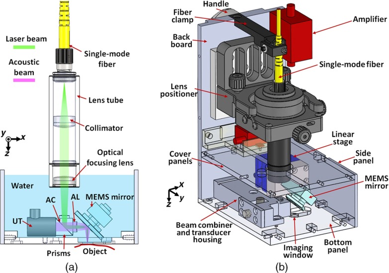
Figure 1(a) is a schematic of the optical and acoustic elements in the OR-PAM handheld probe. A laser beam is directed into the probe through a single-mode fiber (P1-460B-FC-2, Thorlabs), which guides the light to a lens tube in the handheld probe. Two optical lenses (AC127-025-A, Thorlabs; and PAC025, Newport) in the lens tube focus the light to an optical–acoustic beam combiner immersed in water. To seal the lens tube from water, we sealed the second lens at the end of the lens tube with silicone caulk. The beam combiner, composed of an aluminum-coated prism (MRA10-F01, Thorlabs) and an uncoated prism (PS910, Thorlabs), provides acoustic and optical coaxial alignments. The thin aluminum coating reflects light, but transmits sound.22 The focused laser beam is reflected by the MEMS mirror plate onto the surface of the object to be imaged. The resultant photoacoustic waves are reflected by the MEMS mirror plate to an acoustic lens (LC1975, Thorlabs) that is attached to the right side of the combiner. The photoacoustic waves are then detected by a 50-MHz ultrasound transducer (V214-BB-RM, Olympus-NDT), which is tightly attached to the beam combiner from the left. Thus, the laser beam and acoustic beam are confocally aligned through the beam combiner and the MEMS scanning mirror. An optical correction lens (45-119, Edmund) is attached to the top surface of the combiner to correct prism-induced aberration.10 Volumetric imaging is provided by fast rotational scanning along the -axis and slow rotational scanning along the -axis, as well as by the time-resolved detection of the ultrasound signal. The imaging probe is filled with water for ultrasound coupling.
Fig. 1.
Schematic of the OR-PAM handheld probe. (a) 2-D sketch of the optical and acoustic beams in the probe. UT, ultrasound transducer; AC, aluminum coating; AL, acoustic lens. (b) 3-D rendering of the OR-PAM handheld probe. The front and the left side panels are removed for better visualization.
Figure 1(b) is a 3-D rendering of the OR-PAM handheld probe. The probe has dimensions of along the , , and axes. The lens tube is mounted on a five-axis lens positioner (LP-05A, Newport), which is used for fine tuning the laser beam. The MEMS scanning mirror is fixed on a compact linear stage (DS25-XY, Newport) for precise position adjustment. The front, bottom, and cover panels are made of transparent acrylic to help to localize the targeted area. The imaging window on the bottom panel has a diameter of 6 mm and is sealed with a transparent film. A clamp mounted on the top of the probe protects the fiber from excessive bending. The PA signal from the ultrasound transducer is amplified by two integrated amplifiers (ZX60-43-S+ and ZFL-500LN+, Minicircuits) that provide a total amplification of 41 dB. The probe is grounded through a cable attached to the backboard.
The handheld probe is connected to the main system including the laser, MEMS driver, data acquisition (DAQ) devices, and computer. The light is provided by a fiber laser (VPFL-G-10, VGEN) that generates 5-ns pulses at 532 nm, with a pulse repetition rate of 88 kHz. The MEMS mirror is driven by a sinusoidal current from a homemade MEMS driver. The amplified PA signal from the probe is recorded by the DAQ device (ATS9350, Alazar Technologies) with a sampling rate of 250 MHz. A low-pass filter (BLP-70+, Minicircuits) is connected between the amplifier and the analog-to-digital converter to eliminate high-frequency noises. Both the mirror scanning and the DAQ are synchronized with the laser pulse.
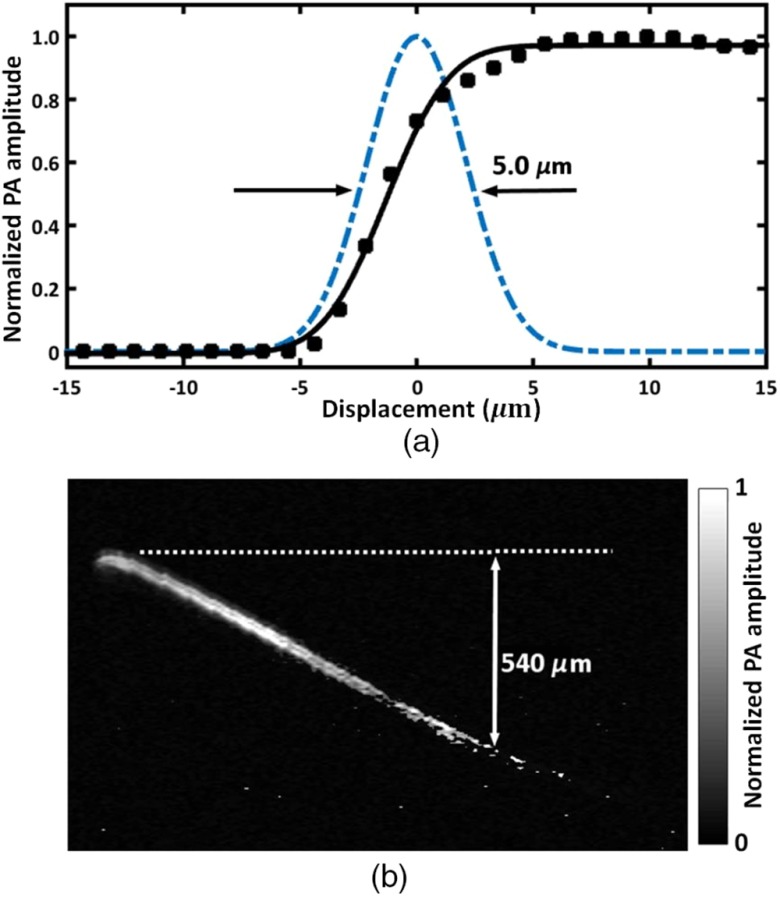
To characterize the lateral resolution of the handheld OR-PAM system, the edge of a sharp blade was imaged in water, with a step size of and a scanning range of along the -axis. After conversion from polar coordinates to Cartesian coordinates, the maximum amplitude projection (MAP) of the B-scan along the acoustic axis was calculated and is plotted as a function of the displacement of the optical and acoustic foci from the edge (Fig. 2). Assuming a Gaussian line spread function, fitting of the measured data to an error function indicates a lateral resolution of (FWHM), which agrees well with the theoretical diffraction-limited focused laser spot size (). The lateral resolution in tissue decreases with imaging depth due to optical scattering.17 The axial resolution of the system is determined by the bandwidth of the ultrasound transducer and was estimated to be . The penetration depth of the handheld probe was quantified by a hair embedded in an optical scattering medium consisting of 2% Intralipid solution (reduced scattering coefficient at 532 nm) and 3% agar gel, which mimics the reduced scattering coefficient of the human skin.23 The projected MAP image is shown in Fig. 2(b). The PA signal from the hair 0.54 mm beneath the surface (indicated by the dashed line) was still detectable when 100-nJ pulse energy was used.
Fig. 2.
Characteristics of the handheld OR-PAM probe. (a) Lateral resolution measurement by imaging a sharp edge. Solid squares: the PA amplitude when the laser beam was scanned across the edge. Solid curve: the fit of the measured data to an error function. Dashed line: the extracted Gaussian-shaped line spread function. (b) Penetration depth measured by a hair embedded in an optical scattering medium mimicking skin tissue. The acoustic attenuation has been compensated for by multiplying the PA signal by a depth-dependent exponential correction factor. The gray bar shows the normalized PA signal amplitude.
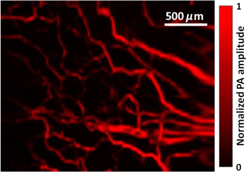
To demonstrate the imaging capability of the handheld OR-PAM probe, blood vessels in a nude mouse ear were imaged in vivo. All experimental animal procedures followed the laboratory animal protocol approved by the Animal Studies Committee of Washington University in St. Louis. The mouse ear was acoustically coupled beneath the imaging window by ultrasound gel. The round-trip scanning frequency of the MEMS mirror was set at 220 Hz for the fast axis and 1 Hz for the slow axis. Then, a region of was imaged with a volumetric imaging rate of 2 Hz (bidirectional scanning). The laser pulse energy was measured as 130 nJ under the imaging window, and an image with an SNR of 28 dB was obtained after averaging over 25 volumes, as shown in Fig. 3.
Fig. 3.
Handheld OR-PAM of vessels in a mouse ear.
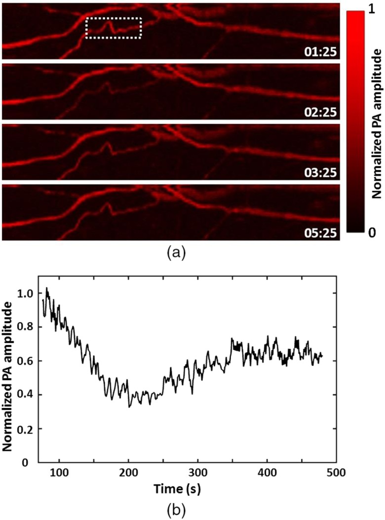
To demonstrate the fast imaging capability of the handheld OR-PAM system, the vessels in a mouse ear were continuously scanned after a tail vein injection of 0.6 mL of 0.9% saline. The postinjection changes in the PA signal from the vessels were monitored with a temporal resolution of 2 Hz. Representative images taken at different times after the injection [Fig. 4(a)] show a decrease in the PA signal followed by a slower recovery process. To quantitatively characterize the changes in the signal from the vessels, we calculated the average of the pixel amplitude over the region indicated by the dashed box. The background signal was calculated by averaging over a region of the same size but without vessels inside. The net signal from the blood vessels is shown as a function of time in Fig. 4(b). As can be seen, the average signal amplitude dropped quickly by 60% in the first 100 s, and then increased slowly to 65% of the initial value in the next 220 s. The initial drop in the signal was probably due to a quick wave of injected saline before it was homogeneously mixed with blood, while the slow increase later was due to the diluting effect of blood.24
Fig. 4.
Hemoglobin concentration monitoring in the vessels in a mouse ear after tail vein injection of 0.9% saline. (a) Representative images recorded at different time points after the injection of 0.6 mL saline. The stamps on the images indicate the time (min:s) after the injection. (b) The signal from the blood vessels within the dashed box in (a) as a function of time. The injection procedure lasted 75 s.
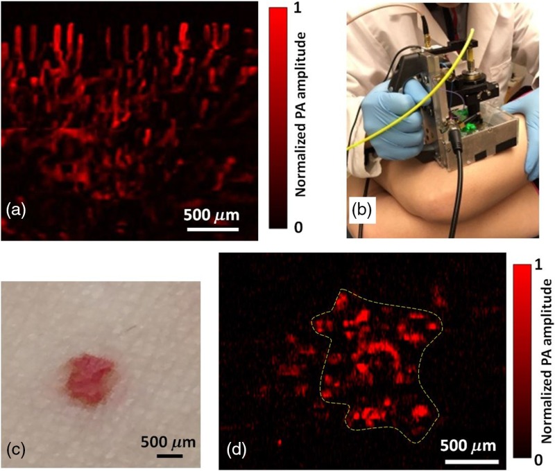
To demonstrate the flexibility of the handheld probe in clinical applications, we tested the system by imaging the human skin. All the human experiments followed a protocol approved by the Institutional Review Board administered by the Human Research Protection Office at Washington University in St. Louis. We first imaged the blood vessels under a cuticle. To obtain higher SNR, the region of interest was scanned repeatedly at a volumetric imaging rate of 2 Hz, and images were averaged over 20 C-scans. It should be noted that the small shift of the same imaging region during the DAQ was corrected by image translation transform, with the shifts calculated from image correlation. In Fig. 5(a), the vessels under the cuticle can be seen clearly, with an SNR of 26 dB.
Fig. 5.
OR-PAM of the human skin by the handheld probe. (a) OR-PAM image of capillaries in a cuticle. (b) Photograph of the OR-PAM handheld probe imaging a red mole on a volunteer’s leg. (c) Photograph of the mole. (d) OR-PAM image of the mole. The color bar shows the normalized PA signal amplitude.
The key advantage of a handheld system is its capability of imaging an area that is usually not accessible by a benchtop device. To demonstrate this advantage, a red mole on a healthy volunteer’s leg was imaged by the handheld OR-PAM probe, as shown in Figs. 5(b)–5(d). The scan fully covered the mole, and a single C-scan PAM image was able to resolve the features, with an SNR of 20 dB. The optical fluence at the skin surface was around , just below the American National Standards Institute limit.25
In summary, we have developed a handheld OR-PAM probe equipped with a water-immersible two-dimensional (2-D)-MEMS mirror for fast skin imaging. Potential applications of the probe have been demonstrated on a mouse ear and human skin. The scanning range of the probe is , and the volumetric imaging rate is 2 Hz, which is mainly limited by the resonant frequency of the fast axis of the MEMS. The penetration depth of the present optical-resolution probe is , which is chiefly limited by the optical scattering in the tissue and can be improved by using near-infrared light that usually undergoes less scattering in biological tissue.17 Compared with the handheld acoustic-resolution photoacoustic microscopy and linear array-based photoacoustic computed tomography, the handheld OR-PAM provides finer spatial resolutions in the superficial region. Moreover, with multiwavelength measurements, OR-PAM has a better accuracy in quantifying the oxygen saturation of hemoglobin.11,26 Therefore, the handheld OR-PAM has potential for intraoperative cancer margin assessment by measuring both the vasculature and the oxygen saturation.
Acknowledgments
This work was funded by the National Institutes of Health (NIH) (DP1-EB016986, R01-CA186567, and R01-CA159959) and National Science Foundation (NSF) (1255930). The authors thank Professor James Ballard for his close reading of the manuscript. L. V. Wang has a financial interest in Microphotoacoustics, Inc., which, however, did not support this work.
Biographies
Li Lin is currently a PhD student at Washington University in St. Louis, under the tutelage of Dr. Lihong V. Wang. He earned his master’s degree at the University of Pennsylvania in 2013 and a bachelor’s degree at Tianjin University in 2011. His research focuses on photoacoustic tomography and microscopy.
Pengfei Zhang obtained his PhD in optics in 2008 from Shanghai Institute of Optics and Fine Mechanics. In 2009 he joined East Carolina University as a postdoc and worked on laser tweezers and Raman spectroscopy. In 2012, he joined Los Alamos National Laboratory as a postdoctoral research associate and his research focused on advanced light microscopy and single molecule spectroscopy. He joined Washington University in St. Louis in 2016 as a research associate and is working on photoacoustic imaging.
Song Xu received his B.S. in optical and electrical engineering from Huazhong Univ. of Science and Technology, P. R. China (2012). He is currently pursuing the Ph. D. in the Department of Electrical and Computer Engineering at Texas A&M University. His current research involves building MEMS scanning mirrors for SAM and PAM and ultrasound image reconstruction
Junhui Shi received his BS in chemical physics from the University of Science and Technology of China. Then he continued to study chemistry and received his PhD at Princeton University, Princeton, New Jersey. He was working on theoretical chemical dynamics and experimental nuclear magnetic resonance spectroscopy. Currently, he is working on photoacoustic imaging in the biomedical engineering department at Washington University in St. Louis, Missouri.
Lei Li earned his bachelor’s and master’s degrees from Harbin Institute of Technology, China, in 2010 and 2012, respectively. Now he is working as a graduate research assistant under the tutelage of Dr. Lihong Wang at Washington University. His current research focuses on photoacoustic microscopy and tomography, especially to improve the photoacoustic imaging speed and to apply it to brain functional and structural imaging.
Junjie Yao received his BE and ME degrees in biomedical engineering from Tsinghua University, Beijing, in 2006 and 2008, respectively, under the tutelage of Prof. Jing Bai. He received his PhD in biomedical engineering at Washington University in St. Louis (WUSTL), in 2013, under the tutelage of Prof. Lihong V. Wang. He is currently a postdoctoral research associate at WUSTL. His research interest is in novel photoacoustic, optical, and ultrasound imaging technologies in biomedicine.
Lidai Wang received the bachelor and master degrees from the Tsinghua University, and received the PhD degree from the University of Toronto. After working as a postdoctoral research fellow in the Washington University in St. Louis, he joined City University of Hong Kong in 2015. His research focuses on biophotonics, biomedical imaging, wavefront engineering, instrumentation and their biomedical applications. He has published 30 articles in peer-reviewed journals and has received four best paper awards from international conferences.
Jun Zou received his PhD degree in electrical engineering from the University of Illinois at Urbana-Champaign in 2002. In 2004, he joined in the department of electrical and computer engineering at Texas A&M University, where he is currently an associate professor. His current research interests lie in the development of micro and nano opto-electro-mechanical devices and systems for biomedical imaging and sensing applications.
Lihong V. Wang received his PhD degree at Rice University, Houston, Texas. Currently, he is holding the Gene K. Beare distinguished professorship of biomedical engineering at Washington University in St. Louis. He has published 400 peer-reviewed journal articles and delivered 400 keynote, plenary, or invited talks. His google scholar h-index and citations have reached 92 and over 34,000, respectively.
References
- 1.American Cancer Society, Skin Cancer Prevention and Early Detection, 2015, http://www.cancer.org/acs/groups/cid/documents/webcontent/003184-pdf.pdf (15 April 2016).
- 2.Yao J., Wang L. V., “Photoacoustic microscopy,” Laser Photonics Rev. 7, 758–778 (2013). 10.1002/lpor.2013.7.issue-5 [DOI] [PMC free article] [PubMed] [Google Scholar]
- 3.Calzavara-Pinton P., et al. , “Reflectance confocal microscopy for in vivo skin imaging,” J. Photochem. Photobiol. 84, 1421–1430 (2008). 10.1111/php.2008.84.issue-6 [DOI] [PubMed] [Google Scholar]
- 4.Arrasmith C., Dickensheets D., Mahadevan-Jansen A., “MEMS-based handheld confocal microscope for in vivo skin imaging,” Opt. Express 18, 3805–3819 (2010). 10.1364/OE.18.003805 [DOI] [PMC free article] [PubMed] [Google Scholar]
- 5.Zhang E., et al. , “Multimodal photoacoustic and optical coherence tomography scanner using an all optical detection scheme for 3D morphological skin imaging,” Biomed. Opt. Express 2, 2202–2215 (2011). 10.1364/BOE.2.002202 [DOI] [PMC free article] [PubMed] [Google Scholar]
- 6.Jung W., et al. , “Handheld optical coherence tomography scanner for primary care diagnostics,” IEEE Trans. Biomed. Eng. 58, 741–744 (2011). 10.1109/TBME.2010.2096816 [DOI] [PMC free article] [PubMed] [Google Scholar]
- 7.Wang L. V., Hu S., “Photoacoustic tomography: in vivo imaging from organelles to organs,” Science 335, 1458–1462 (2012). 10.1126/science.1216210 [DOI] [PMC free article] [PubMed] [Google Scholar]
- 8.Wang L. V., “Multiscale photoacoustic microscopy and computed tomography,” Nat. Photonics 3, 503–509 (2009). 10.1038/nphoton.2009.157 [DOI] [PMC free article] [PubMed] [Google Scholar]
- 9.Hu S., Wang L. V., “Optical-resolution photoacoustic microscopy: auscultation of biological systems at the cellular level,” Biophys. J. 105, 841–847 (2013). 10.1016/j.bpj.2013.07.017 [DOI] [PMC free article] [PubMed] [Google Scholar]
- 10.Maslov K., et al. , “Optical-resolution photoacoustic microscopy for in vivo imaging of single capillaries,” Opt. Lett. 33, 929–931 (2008). 10.1364/OL.33.000929 [DOI] [PubMed] [Google Scholar]
- 11.Yao J., et al. , “Label-free oxygen-metabolic photoacoustic microscopy in vivo,” J. Biomed. Opt. 16, 076003 (2011). 10.1117/1.3594786 [DOI] [PMC free article] [PubMed] [Google Scholar]
- 12.Yao J., et al. , “In vivo photoacoustic imaging of transverse blood flow by using Doppler broadening of bandwidth,” Opt. Lett. 35, 1419–1421 (2010). 10.1364/OL.35.001419 [DOI] [PMC free article] [PubMed] [Google Scholar]
- 13.Chatni M., et al. , “Functional photoacoustic microscopy of pH,” J. Biomed. Opt. 16, 100503 (2011). 10.1117/1.3644495 [DOI] [PMC free article] [PubMed] [Google Scholar]
- 14.Krumholz A., et al. , “Photoacoustic microscopy of tyrosinase reporter gene in vivo,” J. Biomed. Opt. 16, 080503 (2011). 10.1117/1.3606568 [DOI] [PMC free article] [PubMed] [Google Scholar]
- 15.Krumholz A., et al. , “Functional photoacoustic microscopy of diabetic vasculature,” J. Biomed. Opt. 17, 060502 (2012). 10.1117/1.JBO.17.6.060502 [DOI] [PMC free article] [PubMed] [Google Scholar]
- 16.Zhang C., Maslov K., Wang L. V., “Subwavelength-resolution label-free photoacoustic microscopy of optical absorption in vivo,” Opt. Lett. 35, 3195–3197 (2010). 10.1364/OL.35.003195 [DOI] [PMC free article] [PubMed] [Google Scholar]
- 17.Hai P., et al. , “Near-infrared optical-resolution photoacoustic microscopy,” Opt. Lett. 39, 5192–5195 (2014). 10.1364/OL.39.005192 [DOI] [PMC free article] [PubMed] [Google Scholar]
- 18.Yao J., et al. , “Double-illumination photoacoustic microscopy,” Opt. Lett. 37, 659–661 (2012). 10.1364/OL.37.000659 [DOI] [PMC free article] [PubMed] [Google Scholar]
- 19.Yao J., et al. , “High-speed label-free functional photoacoustic microscopy of mouse brain in action,” Nat. Methods 12(5), 407–410 (2015). 10.1038/nmeth.3336 [DOI] [PMC free article] [PubMed] [Google Scholar]
- 20.Xu S., Huang C., Zou J., “Microfabricated water-immersible scanning mirror with a small form factor for handheld ultrasound and photoacoustic microscopy,” J. Micro/Nanolithogr., MEMS, MOEMS 14, 035004 (2015). 10.1117/1.JMM.14.3.035004 [DOI] [Google Scholar]
- 21.Hu S., Maslov K., Wang L., “Second-generation optical-resolution photoacoustic microscopy with improved sensitivity and speed,” Opt. Lett. 36, 1134–1136 (2011). 10.1364/OL.36.001134 [DOI] [PMC free article] [PubMed] [Google Scholar]
- 22.Yao J., et al. , “Wide-field fast-scanning photoacoustic microscopy based on a water-immersible MEMS scanning mirror,” J. Biomed. Opt. 17, 080505 (2012). 10.1117/1.JBO.17.8.080505 [DOI] [PMC free article] [PubMed] [Google Scholar]
- 23.Maslov K., Stoica G., Wang L. V., “In vivo dark-field reflection-mode photoacoustic microscopy,” Opt. Lett. 30, 625–627 (2005). 10.1364/OL.30.000625 [DOI] [PubMed] [Google Scholar]
- 24.Tocantins L., Carroll R., Holburn R., “The clot accelerating effect of dilution on blood and plasma. Relation to the mechanism of coagulation of normal and hemophilic blood,” Blood 6, 720–739 (1951). [PubMed] [Google Scholar]
- 25.American National Standards Institute, American National Standard for the Safe Use of Lasers, American National Standards Institute, New York: (2000). [Google Scholar]
- 26.Lin L., et al. , “In vivo photoacoustic tomography of myoglobin oxygen saturation,” J. Biomed. Opt. 21, 061002 (2015). 10.1117/1.JBO.21.6.061002 [DOI] [PMC free article] [PubMed] [Google Scholar]


