Abstract
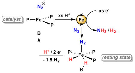
The mechanisms of the few known molecular nitrogen-fixing systems, including nitrogenase enzymes, are of much interest but are not fully understood. We recently reported that Fe-N2 complexes of tetradentate P3E ligands (E = B, C) generate catalytic yields of NH3 under an atmosphere of N2 with acid and reductant at low temperatures. Here we show that these Fe catalysts are unexpectedly robust and retain activity after multiple reloadings. Nearly an order of magnitude improvement in yield of NH3 for each Fe catalyst has been realized (up to 64 equiv NH3 produced per Fe for P3B and up to 47 equiv for P3C) by increasing acid/reductant loading with highly purified acid. Cyclic voltammetry shows the apparent onset of catalysis at the P3BFe-N2/P3BFe-N2− couple and controlled-potential electrolysis of P3BFe+ at −45 °C demonstrates that electrolytic N2 reduction to NH3 is feasible. Kinetic studies reveal first-order rate dependence on Fe catalyst concentration (P3B), consistent with a single-site catalyst model. An isostructural system (P3Si) is shown to be appreciably more selective for hydrogen evolution. In situ freeze-quench Mössbauer spectroscopy during turnover reveals an iron-borohydrido-hydride complex as a likely resting state of the P3BFe-catalyst system. We postulate that HER activity may prevent iron hydride formation from poisoning the P3BFe-system. This idea may be important to consider in the design of synthetic nitrogenases and may also have broader significance given that intermediate metal-hydrides and hydrogen evolution may play a key role in biological nitrogen fixation.
Graphical Abstract
1. INTRODUCTION
The fixation of molecular nitrogen (N2) into ammonia (NH3) is a transformation of fundamental importance to both biology and industry,1 a fact which has prompted mechanistic study of the few known systems capable of catalyzing this reaction. The industrial Haber-Bosch process has been the subject of exhaustive investigation, resulting in a detailed mechanistic understanding in large part supported by surface spectroscopic studies on model systems.2 The nitrogenase family of enzymes provides an example of catalytic N2 conversion under ambient conditions and has also been studied extensively. While many questions remain unanswered regarding the mechanism of nitrogenase, a great deal of kinetic and reactivity information has been collected.3 Additionally, important insights have been provided by protein crystallography, X-ray emission spectroscopy, and site-mutagenesis studies, as well as in situ freeze-quench ENDOR and EPR spectroscopy.4,5
Hypotheses underpinning the mechanisms of both of these systems are bolstered by synthetic model chemistry and efforts to develop molecular N2 conversion catalysts.6 This search has yielded systems capable of the catalytic reduction of N2 to hydrazine (N2H4),7 tris(trimethylsilyl)amine,8 and a few examples of the direct catalytic fixation of N2 to NH3 (Chart 1).8g,9,10,11,12 While a wealth of mechanistic information for the original Mo catalyst system developed by Schrock has been derived from stoichiometric studies and theory,13,14 in situ spectroscopic studies during catalysis were not reported. These synthetic catalysts operate under heterogeneous conditions and are likely to generate mixtures of intermediate species that are both diamagnetic and paramagnetic, making it challenging to reliably determine speciation under turnover. This latter limitation is also true of biological nitrogenases. While CW and pulsed-EPR techniques can and have been elegantly applied,5 such studies are inherently limited in that species/intermediates not readily observable by these techniques will go unnoticed.
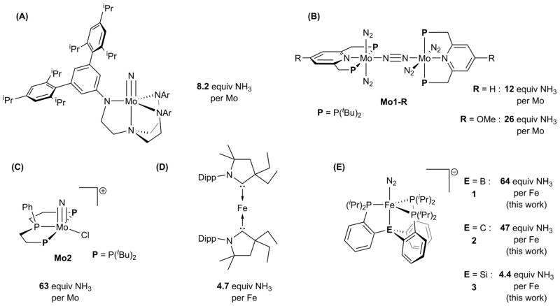
Chart 1. Synthetic catalysts for nitrogen fixation with maximum observed yields of NH3a.
a(A) See reference 9a. (B) See references 10. (C) See reference 11. (D) See reference 8g. (E) See references 12. Note that NH3 equivalents shown represent the highest single-run values that have been reported for the various catalysts shown; direct cross-comparisons of Fe and Mo catalyst performance are tenuous due to the different reaction conditions used.
Iron is the only transition metal that is essential in the cofactor for nitrogenase function, and this fact has motivated a great deal of recent interest in Fe-N2 model chemistry.15 In recent years we have focused on a family of Sacconi-type tetradentate ligands, P3E, in which three phosphine donors are bonded to a central atom through an ortho-phenylene linker (E = B, Si, C). We have shown that P3EM (M = Fe, Co) complexes promote the binding and activation of N2, as well as the functionalization of bound N2 with various electrophiles.16,17,18 Moreover, we discovered that P3BFe (P3B = tris(o-diisopropylphosphinophenyl)borane) and P3CFe (P3C = tris(o-diisopropylphosphinophenyl)methyl) complexes mediate the catalytic reduction of N2 to NH3 at low temperature using a strong acid—[H(OEt2)2][BArF4] (HBArF4)—and a strong reductant—potassium graphite (KC8) (Chart 1, D).12 One unique aspect of these Fe-based systems is their suitability for in situ spectroscopic study by freeze-quench 57Fe Mössbauer spectroscopy. In principle, this technique enables observation of the total Fe speciation as frozen snapshots during turnover.19 For single-site Fe nitrogenase mimics of the type we have developed, analysis of such data is far simpler than in a biological nitrogenase where many iron centers are present.20
For the most active P3BFe catalyst system, many P3BFe-NxHy model complexes that may be mechanistically relevant (e.g., Fe+, Fe-N2−, Fe=NNH2+, Fe-NH3+) have now been independently generated and characterized, including by 57Fe Mössbauer spectroscopy, and these data facilitate interpretation of the freeze-quench Mössbauer data reported here. In combination with chemical quenching methods that we present to study the dynamics of product formation, it becomes possible to attempt to correlate the species observed spectroscopically with the N2 fixing activity to gain a better understanding of the overall catalytic system. Such a strategy complements the studies of model complexes and stoichiometric reactions steps that we have previously undertaken and offers a fuller mechanistic picture. While many questions remain, this approach to studying N2-to-NH3 conversion mediated by synthetic iron catalysts is a mechanistically powerful one.
Here we undertake tandem spectroscopy/activity studies using the P3E (E = B, C, Si) Fe catalyst systems and report the following: (i) two of these Fe-based catalysts (E = B, C) are unexpectedly robust under the reaction conditions, demonstrating comparatively high yields of NH3 that are nearly an order of magnitude larger than in initial reports at lower acid/reductant loadings; (ii) based on electrochemical measurements the dominant catalysis by the P3BFe system likely occurs at the formal P3BFe-N2/P3BFe-N2− couple, corroborated by demonstrating catalysis with Na/Hg and electrolytic N2-to-NH3 conversion in a controlled-potential bulk electrolysis; (iii) the P3BFe system shows first order rate dependence on iron catalyst concentration and zero order dependence on acid concentration; (iv) kinetic competition between rates of N2 versus H+ reduction are a key factor in determining whether productive N2-to-NH3 conversion is observed; and (v) a metal hydride-borohydride species is a resting state of the P3BFe catalysis system.
2. RESULTS AND DISCUSSION
2.1. Increased turnover of Fe-catalyzed N2 fixation and evidence for catalysis at the P3BFe-N2/P3BFe-N2− couple
Following our initial discovery that the addition of excess HBArF4 and KC8 to the anionic dinitrogen complex [P3BFe(N2)][(12-crown-4)2Na] (1) at low temperature in Et2O under an atmosphere of N2 furnishes catalytic yields of NH3, we pursued the optimization of this system for NH3 yield (Eqn. 1).
| (1) |
Under our initially reported conditions (in Et2O at −78 °C with 48 equiv HBArF4 and 58 equiv KC8) the catalysis furnishes 7.0 ± 1.0 equiv of NH3 per Fe atom, corresponding to 44% of added protons being delivered to N2 to make NH3. Initial attempts at optimization showed that neither the overall concentration of the reactants nor the mole ratio of the catalyst substantially altered the yield of NH3 with respect to proton equivalents.
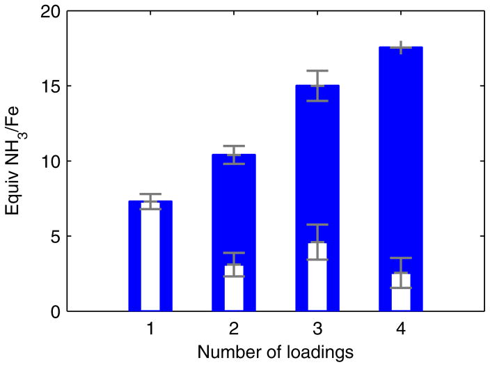
We have since examined whether the post-reaction material retained any catalytic competence when more substrate was delivered. We found that if, after stirring at −78 °C for 1 hour the reaction mixture was frozen (at −196 °C), delivered additional substrate, and then thawed to −78 °C, significantly more NH3 was formed. Iterating this reloading process several times resulted in a steady increase in the total yield of NH3 per Fe atom (Figure 1), demonstrating that some active catalyst remains at −78 °C, even after numerous turnovers. This result implies that the yield of NH3 is limited by competitive consumption of substrate in a hydrogen evolving reaction (HER).
Figure 1.
Yields of NH3 obtained using P3BFe-N2− 1 from successive reloading of HBArF4 and KC8 to reactions maintained at ≤ −70 °C in Et2O. Blue bars denote total observed yields and white inset bars denote the average increase in total yield from the final loading of substrate. Each loading corresponds to 48 equiv HBArF4 and 58 equiv KC8 relative to Fe. Data presented are averages of two experiments.
The apparent stability of at least some of the catalyst at low temperature suggested that it may be possible to observe higher turnover numbers if the catalyst is delivered more substrate at the beginning of the reaction. Indeed, as shown in Table 1, addition of increasing equivalents of HBArF4 and KC8 to 1 at low temperature furnished steadily increasing yields of NH3 relative to catalyst, with a current maximal observed yield of 64 equivalents of NH3 per Fe atom (average of 59 ± 6 over 9 iterations, Table 1, Entries 1–5) at 1500 equiv acid loading. This yield is nearly an order of magnitude larger than that reported at the original acid loading of 48 equiv. We note that the yields of NH3 under these conditions are highly sensitive to the purity of the acid source, unsurprising given the high acid substrate loading relative to catalyst (~1500 equiv HBArF4). To obtain reproducible yields, we have developed a tailored protocol for the synthesis of sufficiently pure NaBArF4/HBArF4, which is detailed in the Supporting Information. It is also important to ensure good mixing and a high gas-liquid interfacial surface area to enable proper mass transfer in the heterogeneous reaction mixture.
Table 1.
NH3 Generation from N2 Mediated by Synthetic Fe Catalystsa
|
| ||||||||
|---|---|---|---|---|---|---|---|---|
| Entry | Catalyst | [Fe] (mM) | HBArF4 equiv | KC8 equiv | Variation | Equiv NH3/Fe | % Yield NH3/H+ | |
| 1 | 1 | 1.3 | 48 | 58 | — | 7.3 ± 0.5 | 45 ± 3 | |
| 2 | 1 | 0.64 | 96 | 58 | — | 12 ± 1 | 38 ± 3 | |
| 3 | 1 | 0.43 | 150 | 185 | — | 17.4 ± 0.2 | 35.6 ± 0.4 | |
| 4 | 1 | 0.08 | 720 | 860 | — | 43 ± 4 | 18 ± 2 | |
| 5 | 1 | 0.04 | 1500 | 1800 | — | 59 ± 6 | 12 ± 1 | |
| 6b | 2 | 1.0 | 37 | 40 | [HBArF4] = 31 mM | 4.6 ± 0.8 | 36 ± 6 | |
| 7 | 2 | 0.56 | 110 | 120 | — | 11.3 ± 0.9 | 31 ± 2 | |
| 8 | 2 | 0.28 | 220 | 230 | — | 14 ± 3 | 19 ± 4 | |
| 9 | 2 | 0.08 | 750 | 810 | — | 19 ± 4 | 7 ± 2 | |
| 10 | 2 | 0.04 | 1500 | 1600 | — | 36 ± 7 | 7 ± 1 | |
| 11c | 3 | 0.58 | 48 | 58 | [HBArF4] = 31 mM | 0.8 ± 0.5 | 5 ± 3 | |
| 12 | 3 | 0.04 | 1500 | 1800 | — | 3.8 ± 0.8 | 0.8 ± 0.2 | |
| 13 | 4-N2d | - | 150 | 185 | 3% toluene | 1.1 ± 0.1 | 2.4 ± 0.3 | |
| 14 | 4-N2 | 0.44 | 150 | 185 | 25% toluene | 5.6 ± 0.9 | 12 ± 2 | |
| 15 | 1 | 0.41 | 150 | 185 | 25 equiv NH3 added | 6.4 ± 0.1 | 13.2 ± 0.2 | |
| 16 | 1 | 0.41 | 150 | 0 | 1900 equiv 10 wt% Na/Hg | 5.0 ± 0.2 | 10.3 ± 0.5 | |
Fe precursor, HBArF4, KC8, and Et2O sealed in a vessel at −196 °C under an N2 atmosphere followed by warming to −78 °C and stirring at −78 °C. Unless noted otherwise, [HBArF4] = 63 mM. Yields are reported as an average of at least 2 iterations; data for individual experimental iterations are presented in the Supporting Information.
Data taken from reference 12b.
Data taken from reference 12a.
Not fully soluble under reaction conditions.
Having discovered that P3BFe-N2− 1 is a significantly more robust catalyst than originally appreciated, we investigated the activity of the alkyl N2 anion [P3CFe-N2][(Et2O)0.5K] (2) toward N2 fixation at higher substrate loading. Significantly higher yields of NH3 per Fe are also attainable using 2 as a catalyst, albeit with roughly 2/3 the activity of 1 (Table 1, Entries 6–10). As a point of comparison, we also submitted the silyl congener [P3SiFe-N2][(12-crown-4)2Na] (3) (P3Si = tris(o-diisopropylphosphinophenyl)silyl) to these conditions and observed dramatically lowered yields of NH3, consistent with earlier reports (Table 1, Entries 11,12). Although the P3SiFe-N2− system 3 displays worse selectivity for NH3 formation vs. HER than 1 (vide infra), 3 still demonstrates catalytic yields of NH3 under sufficiently high substrate loading (up to 4 equiv NH3 per Fe, Table 1 Entry 12).
Table 1 also contains data for catalytic trials with the borohydrido-hydrido complex (P3B)(μ-H)Fe(H)(N2) (4-N2) as a catalyst in mixed Et2O/toluene solvent. In the presence of admixed toluene 4-N2 is observed to be partially soluble and demonstrates competence as a catalyst (Table 1, Entry 14); in the absence of toluene 4-N2 shows poor solubility and lower than catalytic yields of NH3 were observed under the originally reported catalytic conditions (0.50 ± 0.1 equiv NH3 per Fe).12a The significance of these observations is discussed below (section 2.4).
The efficiency of NH3 production with respect to acid substrate decreases under increasingly high turnover conditions for these iron systems. Our understanding of the HER kinetics (vide infra) rationalizes this phenomenon in that under comparatively low catalyst loading (which engenders higher turnover) the background HER should be increasingly competitive, thereby reducing N2-fixing efficiency. The product of the reaction (NH3) may also act as an inhibitor of catalysis. To test this latter possibility, catalytic runs with 150 equiv HBArF4 and 185 equiv KC8 in the presence of 1 were conducted with the inclusion of 25 equiv of NH3 (Table 1, Entry 15). The fixed N2 yield of this reaction is substantially lower than the comparable experiment without added NH3 (Table 1, Entry 3). One contributing cause for NH3 inhibition is that it sequesters HBArF4 as [NH4][BArF4]; however, the yield of NH3 observed in Entry 15 is suppressed compared to an experiment with only 100 equiv HBArF4. This observation indicates that NH3 inhibits the catalytic reaction, and that the degree of inhibition is more substantial than stoichiometric leveling of the acid strength.
We also sought to establish the minimum reducing potential required to drive catalysis with P3BFe-N2− 1. We have shown in previous work that 1 reacts favorably with HBArF4 in Et2O at −78 °C along a productive N2 fixation pathway.18 In brief, 1 can be doubly protonated in Et2O at −78 °C to generate P3BFe=NNH2+ (Eqn. 2). If only stoichiometric acid is present, 1 is instead unproductively oxidized to P3BFe-N2 (Eqn. 3). We have only observed net oxidation in the reaction of the neutral P3BFe-N2 state with HBArF4 in Et2O to produce P3BFe+ (Eqn. 4).
| (2) |
| (3) |
| (4) |
These observations suggest that N2 fixing catalysis likely occurs at the P3BFe-N2/P3BFe-N2− redox couple (−2.2 V vs Fc/Fc+), but not at the P3BFe+/P3BFe-N2 couple (−1.5 V vs Fc/Fc+). We have explored this hypothesis via cyclic voltammetry (CV) experiments. Figure 2 shows electrochemical data for P3BFe+ dissolved in Et2O at −45 °C under 1 atm N2 in the presence of 0.1 M NaBArF4 as a soluble electrolyte to create a modestly conductive ethereal solution.21 The blue trace shows the expected irreversible P3BFe+/P3BFe-N2 couple centered around ~ −1.7 V and the P3BFe-N2/P3BFe-N2− couple at −2.2 V, as previously reported.17a The red trace shows the electrochemical behavior of P3BFe+ in the presence of 5 equiv HBArF4. The data reveal a sharp plateaued increase in current coincident with the P3BFe-N2/P3BFe-N2− redox couple, and very little increase in current at the P3BFe+/P3BFe-N2 couple. The onset of an apparent catalytic response at the P3BFe-N2/P3BFe-N2− couple intimates that electrocatalysis may be feasible, and that chemical reductants with weaker reduction potentials than KC8 may also be competent for N2-to-NH3 conversion catalyzed by P3BFe-N2−. Also, the potential of the apparent catalytic response does not shift from the P3BFe-N2/P3BFe-N2− couple in the absence of acid, indicating that this reduction precedes the first protonation event.
Figure 2.
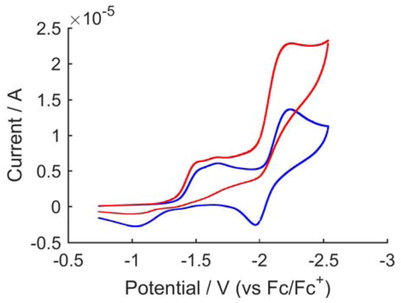
Cyclic voltammetry of [P3BFe][BArF4] in the presence of 0 (blue trace) and 5 (red trace) equiv HBArF4, collected in Et2O with 0.1 M NaBArF4 electrolyte at −45 °C using a glassy carbon electrode and referenced to the Fc/Fc+ couple. Scan rate is 100 mV/s.
To determine whether electrolytic N2-to-NH3 conversion contributes to the catalytic feature observed in the CV data, a controlled-potential bulk electrolysis of P3BFe+ and 10 equiv HBArF4 in Et2O at −45 °C under 1 atm N2 in the presence of 0.1 M NaBArF4 electrolyte with a reticulated vitreous carbon working electrode was performed. The electrolysis was held at −2.6 V (vs Fc/Fc+) for 4.6 hours, after which time 5.85 C of charge had been passed. Product analysis revealed the formation of NH3 (18% faradaic efficiency) as well as H2 (58% faradaic efficiency). The amount of NH3 generated in this experiment corresponds to 0.5 equiv with respect to Fe and 14% yield with respect to acid. When the experiment was performed at higher acid loading (50 equiv), the NH3 yield increased substantially (1.4 equiv per Fe; 8% faradaic efficiency; electrolysis held at −2.3 V in this instance with 13.04 C charge passed over 9 hrs). While these yields of NH3 with respect to Fe do not demonstrate formal turnover, they do suggest that electrocatalytic N2-to-NH3 conversion by this iron system may be feasible. That the NH3 yield increases with increased acid correlates well with our results in the chemical system. Studies to more thoroughly explore the electrocatalytic N2-to-NH3 conversion behavior of P3BFe-species are underway.
The electrochemical data presented in Figure 2 also suggest that chemical reductants with weaker reduction potentials than KC8 may be competent for N2-to-NH3 conversion catalysis by 1. Consistent with this notion we find that catalytic yields of NH3 (5 equiv per Fe) are obtainable using 1 in the presence of 150 equiv HBArF4 and 1900 equiv 10 wt% Na/Hg amalgam under ~1 atm N2 at −78 °C in Et2O (Table 1, Entry 16; a larger excess of 10 wt% Na/Hg amalgam was employed to compensate for the lower surface area of the reagent). This result demonstrates that the catalysis is not unique to the presence of either potassium or graphite. KC8 is a stronger reductant than is needed for N2-to-NH3 conversion, but shows more favorable selectivity for N2 reduction relative to H2 generation than other reductants we have thus far canvassed.
2.2 Kinetics of ammonia and hydrogen formation
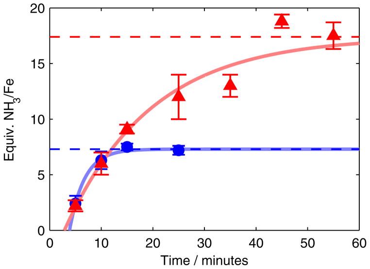
To better understand the competing NH3- and H2-forming reactions that occur during catalysis, we measured the time profiles of product formation using the most active catalyst, P3BFe-N2− 1. Our method for quenching catalytic NH3 production uses rapid freeze-quenching of reactions to −196 °C, followed by addition of tert-butyllithium (tBuLi), and subsequent annealing to −78 °C. Employing this method allows for the measurement of NH3 production as a function of time. The time courses of NH3 formation obtained for the previously reported substrate loading (blue trace)12a as well as a higher substrate loading (red trace) are shown in Figure 3.
Figure 3.
Time profiles of the formation of NH3 from N2 using 1 as a catalyst at −78 °C under previously reported reaction conditions (blue circles, 0.64 mM 1, 48 equiv HBArF4, 58 equiv KC8) and higher-turnover conditions (red triangles, 0.43 mM 1, 150 equiv HBArF4, 185 equiv KC8). Dashed lines show expected final yields from the corresponding entries in Table 1 (Entries 1 and 3). Each point represents an average of two experiments; data for the individual experimental iterations are presented in the Supporting Information. Solid lines are provided as guides for the eye only.
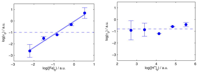
Under both substrate loadings shown in Figure 3, the reaction proceeds to completion at −78 °C. Furthermore, under the higher-turnover conditions (with 150 equiv HBArF4 and 185 equiv KC8, Figure 3, red triangles) the reaction proceeds to completion over ~45 min, a time-scale that enables us to measure the dependence of d[NH3]/dt on the concentrations of the soluble reagents—1 and HBArF4—via the method of initial rates. As shown in Figure 4 (left), an initial rates analysis demonstrates that the reaction is first order in [Fe], which is consistent with the involvement of a monomeric P3BFe species in the turnover-limiting step for NH3 formation. Comparing conditions ranging from 15 mM to 250 mM [HBArF4] revealed no significant correlation between initial [HBArF4] and initial NH3 production rate; for instance, there is no measurable difference in the amount of NH3 produced after five minutes. This observation suggests zero-order rate dependence on acid concentration, which is borne out by the initial rates analysis (Figure 4, right).
Figure 4.
Log-log plots of the initial rate of NH3 formation (υ0) versus initial concentrations of soluble reagents. (Left) υ0 versus [Fe]0 for a range of [1] from 0.11–1.7 mM. The dashed line shows a constant function fit to the mean of the data, while the solid trend line shows the result of least squares linear regression (log(υ0) = (−0.04 ± 0.1) + (1.1 ± 0.1) · log([1]0), r2 = 0.98). (Right) υ0 versus [HBArF4]0 for a range of [HBArF4] from 15–250 mM. The dashed line shows a constant function fit to the mean of the data (RMSE = 0.3), which is not statistically different from the result of a least squares linear regression (RMSE = 0.3). Data for individual experimental iterations and discussion of initial rates estimates are presented in the Supporting Information.
These data provide an estimate of initial turnover frequency (TOF, determined as moles of NH3 produced per minute per Fe atom) of this catalyst system of 1.2 ± 0.1 min−1. While the TOF of this catalyst is not directly comparable to other N2-to-NH3 conversion catalysts due to differences in conditions and substrate, it is notable that 1 under the conditions used here furnishes a substantially higher TOF than the other synthetic systems in Chart 1 for which data is available (Table 2), despite operating over 100 °C lower in temperature (albeit with the benefit of a stronger reductant). MoFe nitrogenase purified from Klebsiella pneumoniae exhibits a TOF of approximately 80 min−1,22 nearly two orders of magnitude larger than the present synthetic Fe system, while operating at room temperature.
Table 2.
Comparison of NH3 Generating Reactionsa
| Catalyst | Temperature (°C) | Maximum yieldd | TOF (min−1) | Efficiency (%) |
|---|---|---|---|---|
| Mo1-Ha | 25 | 12 | 0.14 | 31 |
| Mo2b | 25 | 63 | 0.26 | 35 |
| 1c | −78 | 64 | 1.2 | 12 |
Data for Mo1-H and Mo2 are from reference 11 and depictions of the compounds are presented in Chart 1.
Conditions: 2,6-lutidinium trifluoromethanesulfonate and cobaltocene in toluene.
Conditions: 2,4,6-trimethylpyridinium trifluoromethanesulfonate and decamethylcobaltocene in toluene.
Conditions: HBArF4 and KC8 in diethyl ether.
Expressed in NH3 equivalents.
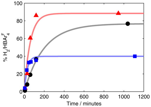
To determine potential HER activity of P3BFe-N2− 1, we measured the time course of H2(g) formation from HBArF4 and KC8 in the absence and presence of 1, under catalytically relevant conditions. As shown in Figure 5, the initial rate of H2(g) evolution at −78 °C is enhanced by the presence of 1. The Fe-catalyzed HER is > 85% complete within the first hour with a final yield of ~40% (blue trace).23 Quantifying the NH3 produced in this reaction (34% yield based on HBArF4) accounts for 74% of the acid added. We also confirm that there is significant background HER from HBArF4 and KC8 (black trace), as expected. We conclude that both catalyzed and background HER are competing with NH3 formation in the catalyst system.
Figure 5.
Time profiles of the formation of H2 from HBArF4 and KC8 in Et2O at −78 °C. Data is presented for the reaction of these reagents alone (black circles) as well as in the presence of 1 (blue squares) and 3 (red triangles). Each time course was collected continuously from a single experiment. Solid lines are provided as guides for the eye only.
As a point of comparison, we also measured the rate of H2 evolution in the presence of P3SiFe-N2− (3). As shown in Figure 5, 3 also catalyzes HER, with an initial rate that is comparable to 1. However, in this case, H2 evolution approaches completion over two hours, resulting in a final measured yield of 88%. This is consistent with the low N2-fixing activity of 3; in the absence of a competitive NH3-producing reaction, 3 catalyzes the reduction of protons to H2. Understanding the fundamental differences that give rise to the divergent selectivity of these Fe catalysts is an important goal in the context of designing selective N2 reduction catalysts.
2.3 Spectroscopic characterization of Fe speciation under turnover
Considering the relatively slow rate of NH3 formation ascertained from low-temperature quenching experiments, we sought to determine the Fe speciation under turnover using the P3BFe-N2− catalyst 1. By rapidly freeze-quenching reaction mixtures using 57Fe-enriched 1 as a catalyst, time-resolved Mössbauer spectra can be obtained reflective of catalysis.24
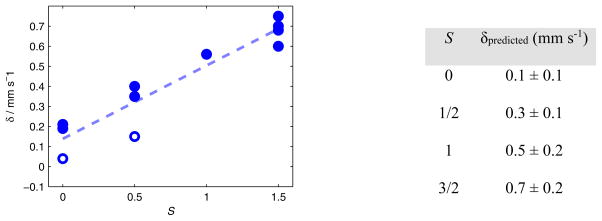
The Mössbauer parameters of some independently synthesized P3BFe species that may be relevant to the present catalysis have been measured and are collected in Table 3. Mössbauer isomer shifts (δ) can often be used to assign the relative oxidation state of structurally related compounds,16b,25 yet in this series of P3BFe compounds there is a poor correlation between δ and formal oxidation state assignments (e.g. Fe-N2− and Fe=NNH2+ species have nearly identical isomer shifts). This fact reflects the high degree of covalency present in these P3BFe-NxHy complexes, skewing classical interpretations of the Mössbauer data; the degree of true oxidation/reduction at the iron centers in P3BFe-NxHy species is buffered by strong covalency with the surrounding ligand field.26,27 We do, however, find a useful linear correlation (r2 = 0.90) between the measured ground spin states (S) of P3BFe-NxHy compounds and δ (Figure 6),28 providing an empirical relationship that guides analysis of Mössbauer spectra obtained from catalytic reactions. Ground spin states can be reliably correlated with the type of NxHy ligand, and possibly the presence of hydride ligands, coordinated to a P3BFe center. This knowledge, combined with freeze-quench Mössbauer data, enables us to predict with some confidence the type(s) of Fe species that are present in a spectrum obtained after freeze-quenching during turnover.
Table 3.
Mössbauer parameters for P3BFe complexesa
| Compound | S | Conditions | δ (mm s−1) | ΔEQ (mm s−1) |
|---|---|---|---|---|
| P3BFe+b | 3/2 | Frozen solution, 50 mT | 0.75 | 2.55 |
| P3BFe-N2H4+ | 3/2 | Frozen solution, 50 mT | 0.7 | 2.30 |
| P3BFe-NH3+ | 3/2 | Frozen solution, zero field | 0.68 | 1.94 |
| P3BFe-NH2 | 3/2 | Frozen solution, zero field | 0.60 | 1.47 |
| P3BFe-N2b | 1 | Frozen solution, 50 mT | 0.56 | 3.34 |
| P3BFe-N2−b | 1/2 | Frozen solution, 50 mT | 0.40 | 0.99 |
| P3BFe-NNH2+b | 1/2 | Frozen solution, 50 mT | 0.35 | 1.02 |
| P3BFe-NAd+ | 1/2 | Powder, 50 mT | 0.15 | 1.31 |
| (P3B)(μ-H)Fe(H)(N2) | 0 | Frozen solution, zero field | 0.21 | 1.44 |
| (P3B)(μ-H)Fe(H)(H2) | 0 | Frozen solution, zero field | 0.19 | 1.55 |
| P3BFe-NAd | 0 | Powder, zero field | 0.04 | 1.40 |
All data were collected at 80 K under the conditions noted; external magnetic fields applied in parallel mode.
Data taken from reference 18.
Figure 6.
A plot of δ versus ground spin-state S for the compounds listed in Table 3 (blue circles), along with a linear least-squares fit to the data (dotted line, r2 = 0.90). The isomer shifts of the P3BFe-NAd0/1+ are highlighted by open circles.28 The table to the right lists the expectation values for δ based on S computed from the linear fit (ranges reported as 95% confidence interval).
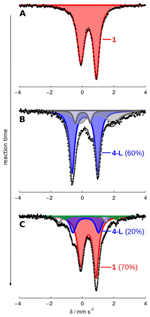
Figure 7 shows time-resolved Mössbauer spectra of freeze-quenched catalytic reaction mixtures of P3BFe-N2− anion 1 with 48 equiv of HBArF4 and 58 equiv of KC8. Figure 7A shows the spectrum of catalyst 1 as a 0.64 mM solution in THF, which features a sharp, asymmetric quadrupole doublet at 80 K in the presence of a 50 mT external magnetic field. Figure 7B shows the spectrum of a catalytic reaction mixture freeze-quenched after 5 minutes of stirring, revealing the major Fe species (blue, representing ca. 60% of all Fe) present during active turnover to have parameters δ = 0.16 ± 0.2 mm s−1 and ΔEQ = 1.63 ± 0.03 mm s−1, which, within the error of the simulation, is consistent with the diamagnetic borohydrido-hydrido species (P3B)(μ-H)Fe(H)(L) (4-L), where L = N2 or H2.29 This observation correlates well with the previously reported result that 4-N2 is produced from the reaction of 1 with smaller excesses of HBArF4 and KC8.12a Further corroborating this assignment, data collected at liquid He temperature with a small applied magnetic field suggest that this species is a non-Kramer’s spin system,30 and should be S = 0 given the observed correlation between δ and S (vide supra). Also present in Figure 7B is a minor component (~8%, shown in white) with parameters δ = 0.02 ± 0.2 mm s−1 and ΔEQ = 0.97 ± 0.2 mm s−1, and a broad residual absorbance centered at δ ≈ 0.9 mm s−1 encompassing a width of ~2 mm s−1 (representing ca. 20–30% of all Fe in the sample, shown in grey). Due to the broadness of the latter resonance (Γ ≈ 1 mm s−1), this feature could not be accurately modeled. Nevertheless, the signal is consistent with several known S = 3/2 P3BFe species. For example, the vacant cation, P3BFe+, and the cationic species P3BFe-N2H4+ and P3BFe-NH3+, are S = 3/2 species and give rise to quadrupole doublets that lie within the envelope of this broad signal (Table 3, Entries 1–3).31 The utility of freeze-quench 57Fe Mössbauer spectroscopy is evident; in a single spectral snapshot the presence of P3BFe-components with varied spin states including S = 0, 1/2, 1, and 3/2 are observed.
Figure 7.
Frozen solution Mössbauer spectra collected at 80 K in the presence of a 50 mT parallel magnetic field. (A) Spectrum of 1 (0.64 mM in THF); (B) a catalytic mixture (Et2O, 0.64 mM 1, 48 equiv HBArF4, 58 equiv KC8) freeze-quenched after 5 minutes of stirring at −78 °C; (C) a catalytic mixture (Et2O, 0.64 mM 1, 48 equiv HBArF4, 58 equiv KC8) freeze-quenched after 25 minutes of stirring at −78 °C. Data are presented as black points and simulations as solid grey lines with components plotted as solid areas underneath the curve. For parameters of individual components see the SI.
Figure 7C shows that the primary Fe species present after 25 minutes of reaction time is the starting catalyst 1 (shown in red, representing ca. 70% of all Fe in the sample). Also present is ca. 20% of the species we assign as 4-L (δ = 0.22 ± 0.2 mm s−1 and ΔEQ = 1.62 ± 0.03 mm s−1, shown in blue), < 5% of the neutral dinitrogen complex, P3BFe-N2 (green), and ~7% of an as-yet unknown species with parameters δ = 0.00 ± 0.02 mm s−1 and ΔEQ = 2.97 ± 0.06 mm s−1 (white). Thus, as acid substrate is consumed in the reaction to produce NH3 and H2, the mixture of Fe species shown in Figure 7B at an early time point evolves back to the starting material 1. A slight residual excess of KC8 is needed to ensure recovery of the active catalyst. These data help rationalize the results of the substrate reloading experiments (vide supra).
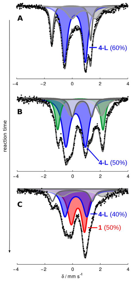
The increasingly low Fe concentrations used to achieve the highest yields of NH3 reported here make the collection of well-resolved Mössbauer spectra under such conditions challenging. Nonetheless, we repeated freeze-quench experiments for one set of higher-turnover conditions (Figure 8). Although in this case the Fe speciation at intermediate times appears more complex, these data exhibit the same gross behavior shown in Figure 7; under active turnover the major Fe species present is consistent with hydride 4-L (≥ 50%, average parameters δ = 0.20 ± 0.2 mm s−1 and ΔEQ = 1.49 ± 0.09 mm s−1, Figure 8A,B32 ), and as the extent of reaction increases significant amounts of P3BFe-N2− 1 reform (Figure 8C33).
Figure 8.
Frozen solution Mössbauer spectra collected at 80 K in the presence of a 50 mT parallel magnetic field. (A) A catalytic mixture (Et2O, 0.43 mM 1, 150 equiv HBArF4, 185 equiv KC8) freeze-quenched after 5 minutes of stirring at −78 °C; (B) a catalytic mixture (Et2O, 0.43 mM 1, 150 equiv HBArF4, 185 equiv KC8) freeze-quenched after 10 minutes of stirring at −78 °C; (C) a catalytic mixture (Et2O, 0.43 mM 1, 150 equiv HBArF4, 185 equiv KC8) freeze-quenched after 25 minutes of stirring at −78 °C. Data presented as black points, simulations as solid grey lines with components plotted as solid areas underneath the curve. For parameters of individual components, see SI.
2.4 Precatalyst activity of (P3B)(μ-H)Fe(H)(N2) (4-N2) and identification of a catalyst resting state
The observations presented in section 2.3 suggest that hydride 4-L builds up as the major Fe-containing species during active turnover and appears to be converted back to the active catalyst 1 when catalysis is complete. We previously observed that this species can form under conditions that model the catalytic conditions (10 equiv acid/12 equiv reductant) and our initial thinking that 4-N2 may be a catalyst deactivation product was guided by the poor activity of isolated 4-N2 as a precatalyst under the standard conditions (generating only 0.5 ± 0.1 equiv NH3 per Fe at 50 equiv acid/60 equiv reductant).12a However, in that initial report we also noted that isolated 4-N2 is not solubilized under the catalytic conditions. Therefore, in light of the current in situ spectroscopy, and the observation that 4-N2 liberated some NH3 under the original conditions, we wondered whether its insolubility may be what is responsible for its comparative low activity as an isolated precursor. If 4-N2 is brought into solution, or formed in solution during turnover, it may exhibit activity. To test this hypothesis we explored the activity of 4-N2 under modified catalytic conditions where a toluene/Et2O mixture (which improves the solubility of 4-N2) was employed as the solvent. In this case we find that 4-N2 serves as a viable precatalyst (Table 1, Entries 13, 14). We suppose then that under the standard conditions (in pure Et2O), if 4-L is generated in solution during catalysis, it should be able to react productively so long as it does not irreversibly precipitate, which may be slow at −78 °C. Accordingly, we have observed that the Mössbauer spectrum of a sample taken from a standard catalytic mixture as described in section 2.3 can be filtered at low temperature and still displays substantial 4-L.
These results suggest the feasibility of the stoichiometric transformation of hydride 4-L into N2 anion 1 under catalytically relevant conditions. In a previous report, we showed that 4-N2 is stable for short periods to either HBArF4 or KC8 in Et2O at room temperature, again noting its insolubility under these conditions.12a Given the results above, we have reinvestigated this reactivity in Et2O/toluene mixtures. Thus the reaction of 4-N2 with 1 equiv of HBArF4 in 6:1 d8-toluene:Et2O results in consumption of the starting material along with the appearance of several new, paramagnetically-shifted 1H NMR resonances. We hypothesize that protonolysis of either the terminal or bridging hydride moieties in 4-N2 produces a cationic “P3BFe-H+” species, which may then be reduced to liberate 0.5 equiv of H2 and re-enter the catalytic manifold of {P3BFe-N2}n species under an N2 atmosphere. Indeed, the sequential addition of 1.5 equiv of HBArF4 followed by 6 equiv of KC8 to 4-N2 at −78 °C in 3:1 Et2O:toluene produces substantial amounts of 1 (32% yield, unoptimized; Scheme 1). This stoichiometric reactivity provides support for the idea that as 4-L is formed under the standard reaction conditions it can react with acid and reductant to produce the starting catalyst 1, consistent with the observations provided in section 2.3.
Scheme 1.
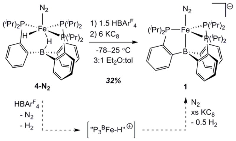
Stoichiometric conversion of 4-N2 into 1 under catalytically relevant conditions. A proposed reaction pathway is shown along the dashed arrows. “P3BFe-H+” is a plausible intermediate of this conversion but has not been thoroughly characterized.
Given that (i) 4-L appears to be the predominant Fe-containing species observed by freeze-quench Mössbauer spectroscopy under turnover conditions at early time points, (ii) that this species serves as a competent precatalyst when solubilized, and (iii) 4-N2 can be synthetically converted to 1 by HBArF4 and KC8, we conclude that 4-L is a major resting state of the catalysis. This conclusion does not require 4-L to be an “on path” intermediate; we instead think 4-L is more likely a resting state that ties up the catalyst, but one that reversibly leaks into the on-path catalytic cycle in which 1 is ultimately protonated.
The observation of a hydride resting state for this synthetic Fe catalyst may have additional relevance in the context of biological nitrogen fixation, where the intermediacy of metal hydride species has been proposed on the basis of spectroscopic data obtained during turnover.5 It has further been proposed that the reductive elimination of hydrides as H2 may be a requisite component of N2 binding to the nitrogenase active-site cofactor,22,34,35 giving rise to obligate H2 evolution in the limiting stoichiometry of N2 conversion to NH3.36 The results described here directly implicate the relevance of a synthetic iron hydride species to a system capable of catalytic N2-to-NH3 conversion. This in turn motivates complimentary model reactivity studies on iron hydride species such as 4-L, targets whose relevance might otherwise be overlooked.
2.5 Summary of mechanistically relevant observations
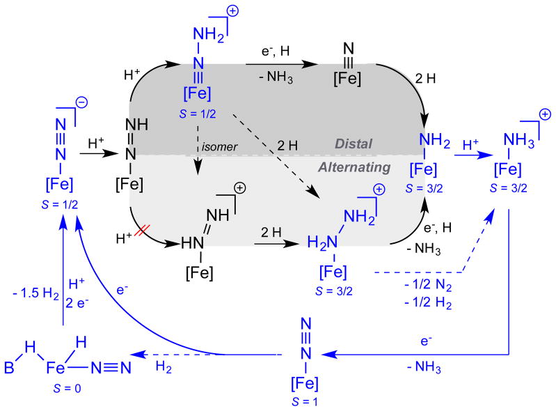
To help collect the information presented here and in related studies of the P3BFe-system, Scheme 3 provides a mechanistic outline for the key iron species and plausible transformations we think are most relevant to the catalytic N2-to-NH3 conversion cycle catalyzed by P3BFeN2− 1. The complexes shown in blue, along with their respective spin states S, have been thoroughly characterized. Also, the net conversions between complexes that are indicated by solid blue arrows have been experimentally demonstrated. Those complexes depicted in black have not (as yet) been experimentally detected.
Scheme 3.
Possible catalytic scenarios for N2-to-NH3 conversion by 1. [Fe] = P3BFe. Thoroughly characterized species and their respective ground spin states S are shown in blue, while as yet undetected species are shown in black. Blue arrows indicate known pathways that are likely kinetically competent (solid) at −78 °C. Dashed arrows are likely incompetent at −78 °C.
Several results are worth underscoring. (i) We have characterized the S = 3/2, substrate-free state P3BFe+, and shown that it binds N2 upon electron loading, generating S = 1 P3BFe-N2 or S = ½ P3BFe-N2− depending on reducing equivalents provided.12a,17 P3BFe+ is competent for catalytic N2-to-NH3 conversion,12a and facilitates this conversion electrolytically as established herein. (ii) The most reduced state, P3BFe-N2− 1, can be doubly protonated at low temperature to generate P3BFe=N-NH2+, a distal pathway intermediate.18 This S = 1/2 species features a short Fe-N multiple bond (~1.65 Å). Its diamagnetic relative, P3sSiFe=N-NH2+, has very recently been structurally characterized.37 (iii) The P3BFe=N-NH2+ intermediate anneals (in the absence of reductant) to generate significant amounts of P3BFe-NH3+;12a,18 (iv) P3BFe-NH3+ can also be generated by protonation of P3BFe-NH2, and reductive displacement of NH3 from P3BFe-NH3+ under N2 regenerates P3BFe-N2−.12a
Also worth emphasizing is that diamagnetic P3SiFe=N-NH2+ can be reduced at low temperature to S = 1/2 P3SiFe=N-NH2, and this species in the presence of additional acid and reductant evolves to a mixture of P3SiFe-N2H4+ and P3SiFe-NH3+.37 P3SiFe-N2H4+, and also P3BFe-N2H4+, readily disproportionate the bound N2H4 to generate the corresponding NH3 adducts P3SiFe-NH3+ and P3BFe-NH3+,12a,16b each of which evolves NH3 upon reduction to regenerate (under N2) P3BFe-N2− 1 and P3SiFe-N2−, respectively. The reaction pathway observed for P3SiFe=N-NH2+, more readily studied than for P3BFe=N-NH2+ because P3SiFe=N-NH2+ can be isolated in pure form, highlights the possibility of a hybrid crossover mechanistic pathway wherein a distal intermediate (Fe=N-NH2) traverses to an alternating intermediate (Fe-N2H4) that may then be converted to NH3, possibly via disproportionation.18,37 By demonstrating first-order rate dependence on the concentration of P3BFe-N2−, [1], the present study remains consistent with our hypothesis that a single-site mechanism is likely operative during N2-to-NH3 conversion catalysis. The direct observation of both 1 and its neutral form P3BFe-N2 in catalytic mixtures by freeze-quench Mössbauer spectroscopy lends further credence to this idea.
A plausible pathway for the formation of the putative resting state species 4-L would be hydrogenation of P3BFe-N2 by evolved H2 side-product during catalysis. This process has been demonstrated independently at room temperature in benzene.29 Follow-up control experiments in d8-toluene, however, suggest that this reaction is not kinetically competent at −78 °C. One alternative pathway for the formation of 4-L during catalysisis via bimolecular H-atom transfer from the unobserved intermediate P3BFe-N2H (e.g., 2 P3BFe-N2H → 4-L + P3BFe-N2), a process that could compete with productive protonation to generate P3BFe=N-NH2+. Efforts are ongoing to find conditions under which P3BFe-N2H can be generated, characterized, and studied.
3. CONCLUSION
In the present study we have shown that N2-fixing catalyst systems with P3EFe (E = B, C, Si) species give rise to high yields of NH3 if supplied with sufficient acid and reductant. These yields (for E = B and C) compare very favorably to the most active known Mo catalysts and are almost an order of magnitude greater than the yields presented in our previous reports. While we do not rule out some degree of catalyst degradation at −78 °C, these iron catalysts are unexpectedly robust and it is possible that the lower efficiency of catalysis at higher turnover is in part due to build-up of NH3 product, which is an inhibitor. We have also provided new mechanistic insights for reactions with catalyst P3BFe-N2− 1, such as the observation that catalysis proceeds at −78 °C, the demonstration of first-order rate dependence on catalyst concentration, the demonstration of zeroth-order rate dependence on HBArF4 concentration, and the observation that 1 catalyzes HER as well as NH3 formation. Preliminary electrochemistry data suggests that catalysis by the P3BFe system can be driven at the formal P3BFe-N2/P3BFe-N2− couple around −2.2 V vs Fc/Fc+, consistent with Na/Hg also serving as a viable reductant for catalytic turnover. Cyclic voltammetry and controlled potential electrolysis of P3BFe+ at −45 °C demonstrate that electrolytic N2 reduction is possible.
The present study has also demonstrated the utility of coupling in situ freeze-quench 57Fe Mössbauer spectroscopy with kinetic analysis of product formation as a powerful tool for the mechanistic study of Fe-catalyzed N2 fixation. To date, no synthetic molecular N2-to-NH3 conversion catalyst system had been studied spectroscopically under active turnover conditions. Our freeze-quench Mössbauer results suggest that 4-L is a resting state of the overall catalysis; this hydride species, which we previously posited to be primarily a catalyst sink, can instead reenter the catalytic pathway via its conversion to catalytically active P3BFe-N2− 1. This observation underscores the importance of understanding metal hydride reactivity in the context of Fe-mediated nitrogen fixation. It may be that HER activity provides a viable strategy for recovering catalytically active states from the unavoidable generation of iron hydride intermediates.
Supplementary Material
Acknowledgments
This work was supported by the NIH (GM 070757) and the Gordon and Betty Moore Foundation. T.J.D.C. acknowledges the support of the NSF for a Graduate Fellowship (GRFP) and N.B.T. acknowledges the support of the Resnick Sustainability Institute at Caltech for a Graduate Fellowship.
Footnotes
The authors declare no competing financial interests.
Experimental procedures and data for individual experiments. The Supporting Information is available free of charge on the ACS Publications website at http://pubs.acs.org.
References
- 1.Smil V. Enriching the Earth. Cambridge: MIT Press; 2001. [Google Scholar]
- 2.(a) Ertl G. J Vac Sci Technol A. 1983;1:1247. [Google Scholar]; (b) Ertl G. Angew Chem Int Ed. 2008;47:3524. doi: 10.1002/anie.200800480. [DOI] [PubMed] [Google Scholar]
- 3.Burgess BK, Lowe DJ. Chem Rev. 1996;96:2983. doi: 10.1021/cr950055x. [DOI] [PubMed] [Google Scholar]
- 4.(a) Howard JB, Rees DC. Chem Rev. 1996;96:2965. doi: 10.1021/cr9500545. [DOI] [PubMed] [Google Scholar]; (b) Einsle O, Tezcan FA, Andrade SLA, Schmid B, Yoshida M, Howard JB, Rees DC. Science. 2002;297:1696. doi: 10.1126/science.1073877. [DOI] [PubMed] [Google Scholar]; (c) Spatzal T, Aksoyoglu M, Zhang L, Andrade SLA, Schleicher E, Weber S, Rees DC, Einsle O. Science. 2011;334:940. doi: 10.1126/science.1214025. [DOI] [PMC free article] [PubMed] [Google Scholar]; (d) Kowalska J, DeBeer S. Biochim Biophys Acta-Molecular Cell Research. 2015;1853:1406. doi: 10.1016/j.bbamcr.2014.11.027. [DOI] [PubMed] [Google Scholar]
- 5.Hoffman BM, Lukoyanov D, Yang ZY, Dean DR, Seefeldt LC. Chem Rev. 2014;114:4041. doi: 10.1021/cr400641x. [DOI] [PMC free article] [PubMed] [Google Scholar]
- 6.(a) Chatt J, Leigh GJ. Chem Soc Rev. 1972;1:121. [Google Scholar]; (b) Khoenkhoen N, de Bruin B, Reek JNH, Dzik WI. Eur J Inorg Chem. 2015;4:567. [Google Scholar]
- 7.Bazhenova TA, Shilov AE. Coord Chem Rev. 1995;144:69. [Google Scholar]
- 8.(a) Shiina K. J Am Chem Soc. 1972;94:9266. [Google Scholar]; (b) Komori K, Oshita H, Mizobe Y, Hidai M. J Am Chem Soc. 1989;111:1939. [Google Scholar]; (c) Tanaka H, Sasada A, Kouno T, Yuki M, Miyake Y, Nakanishi H, Nishibayashi Y, Yoshizawa K. J Am Chem Soc. 2011;133:3498. doi: 10.1021/ja109181n. [DOI] [PubMed] [Google Scholar]; (d) Yuki M, Tanaka H, Sasaki K, Miyake Y, Yoshizawa K, Nishibayashi Y. Nat Commun. 2012;3:1254. doi: 10.1038/ncomms2264. [DOI] [PubMed] [Google Scholar]; (e) Ogawa T, Kajita Y, Wasada-Tsutsui Y, Wasada H, Masuda H. Inorg Chem. 2013;52:182. doi: 10.1021/ic301577a. [DOI] [PubMed] [Google Scholar]; (f) Liao Q, Saffon-Merceron N, Mézailles N. Angew Chem Int Ed. 2014;53:14206. doi: 10.1002/anie.201408664. [DOI] [PubMed] [Google Scholar]; (g) Ung G, Peters JC. Angew Chem Int Ed. 2015;54:532. doi: 10.1002/anie.201409454. [DOI] [PMC free article] [PubMed] [Google Scholar]; (h) Siedschlag RB, Bernales V, Vogiatzis KD, Planas N, Clouston LJ, Bill E, Gagliardi L, Lu CC. J Am Chem Soc. 2015;137:4638. doi: 10.1021/jacs.5b01445. [DOI] [PubMed] [Google Scholar]
- 9.(a) Yandulov DV, Schrock RR. Science. 2003;301:76. doi: 10.1126/science.1085326. [DOI] [PubMed] [Google Scholar]; (b) Ritleng V, Yandulov DM, Weare WW, Schrock RR, Hock AS, Davis WM. J Am Chem Soc. 2004;126:6150. doi: 10.1021/ja0306415. [DOI] [PubMed] [Google Scholar]
- 10.(a) Arashiba K, Miyake Y, Nishibayashi Y. Nat Chem. 2011;3:120. doi: 10.1038/nchem.906. [DOI] [PubMed] [Google Scholar]; (b) Tanka H, Arashiba K, Kuriyama S, Sasada A, Nakajima K, Yoshizawa K, Nishibayashi K. Nat Commun. 2014;5:3737. doi: 10.1038/ncomms4737. [DOI] [PMC free article] [PubMed] [Google Scholar]; (c) Kuriyama S, Arashiba K, Nakajima K, Tanaka H, Kamaru N, Yoshizawa K, Nishibayashi Y. J Am Chem Soc. 2014;136:9719. doi: 10.1021/ja5044243. [DOI] [PubMed] [Google Scholar]
- 11.Arashiba K, Kinoshita E, Kuriyama S, Eizawa A, Nakajima K, Tanaka H, Yoshizawa K, Nishibayashi Y. J Am Chem Soc. 2015;137:5666. doi: 10.1021/jacs.5b02579. [DOI] [PubMed] [Google Scholar]
- 12.(a) Anderson JS, Rittle J, Peters JC. Nature. 2013;501:84. doi: 10.1038/nature12435. [DOI] [PMC free article] [PubMed] [Google Scholar]; (b) Creutz S, Peters JC. J Am Chem Soc. 2014;136:1105. doi: 10.1021/ja4114962. [DOI] [PMC free article] [PubMed] [Google Scholar]; (c) Del Castillo TJ, Thompson NB, Suess DLM, Ung G, Peters JC. Inorg Chem. 2015;54:9256. doi: 10.1021/acs.inorgchem.5b00645. [DOI] [PMC free article] [PubMed] [Google Scholar]
- 13.Schrock RR. Angew Chem Int Ed. 2008;47:5512. doi: 10.1002/anie.200705246. [DOI] [PubMed] [Google Scholar]
- 14.For theoretical work regarding the (PNP)Mo system developed by Nishibayashi, see references 10b,c and also Tian YH, Pierpont AW, Batista ER. Inorg Chem. 2014;53:4177. doi: 10.1021/ic500221n.
- 15.See for example: McWilliams SF, Holland PL. Acc Chem Res. 2015;48:2059–2065. doi: 10.1021/acs.accounts.5b00213.Field LD, Li HL, Dalgarno SJ, Turner P. Chem Commun. 2008:1680–1682. doi: 10.1039/b802039f.Crossland JL, Tyler DR. Coord Chem Rev. 2010;254:1883–1894.Peters JC, Mehn MP. Bio-Organometallic Approaches to Nitrogen Fixation. In: Tolman WB, editor. Activation of Small Molecules. Wiley-VCH; Weinheim, Germany: 2006. p. 81.Hendrich MP, Gunderson W, Behan RK, Green MT, Mehn MP, Betley TA, Lu CC, Peters JC. Proc Natl Acad Sci U S A. 2006;103:17107–17112. doi: 10.1073/pnas.0604402103.Grubel K, Brennessel WW, Mercado BQ, Holland PL. J Am Chem Soc. 2014;136:16807. doi: 10.1021/ja507442b.
- 16.(a) Mankad NP, Whited MT, Peters JC. Angew Chem Int Ed. 2007;46:5768. doi: 10.1002/anie.200701188. [DOI] [PubMed] [Google Scholar]; (b) Lee Y, Mankad NP, Peters JC. Nature Chem. 2010;2:558. doi: 10.1038/nchem.660. [DOI] [PMC free article] [PubMed] [Google Scholar]
- 17.(a) Moret ME, Peters JC. Angew Chem Int Ed. 2011;50:2063. doi: 10.1002/anie.201006918. [DOI] [PMC free article] [PubMed] [Google Scholar]; (b) Moret ME, Peters JC. J Am Chem Soc. 2011;133:18118. doi: 10.1021/ja208675p. [DOI] [PMC free article] [PubMed] [Google Scholar]; (c) Anderson JS, Moret ME, Peters JC. J Am Chem Soc. 2013;135:534. doi: 10.1021/ja307714m. [DOI] [PMC free article] [PubMed] [Google Scholar]
- 18.Anderson JS, Cutsail G, III, Rittle J, Connor B, Gunderson W, Zhang L, Hoffman B, Peters JC. J Am Chem Soc. 2015;137:7803. doi: 10.1021/jacs.5b03432. [DOI] [PMC free article] [PubMed] [Google Scholar]
- 19.(a) Krebs C, Price JC, Baldwin J, Saleh L, Green MT, Bollinger JM. Inorg Chem. 2005;44:742. doi: 10.1021/ic048523l. [DOI] [PubMed] [Google Scholar]; (b) Krebs C, Bollinger JM. Photosynth Res. 2009;102:295. doi: 10.1007/s11120-009-9406-6. [DOI] [PubMed] [Google Scholar]
- 20.(a) McLean PA, Papaefthymiou V, Orme-Johnson WH, Münck E. J Biol Chem. 1987;262:12900. [PubMed] [Google Scholar]; (b) Yoo SJ, Angove HC, Papaefthymiou V, Burgess BK, Münck E. J Am Chem Soc. 2000;122:4926. [Google Scholar]
- 21.Data were not collected at −78 °C due to lower solubility of NaBArF4 at that temperature.
- 22.Lowe DJ, Thorneley RNF. Biochem J. 1984;224:877. doi: 10.1042/bj2240877. [DOI] [PMC free article] [PubMed] [Google Scholar]
- 23.This represents a lower limit of the H2 produced due to leakage using a set-up that enables quantification of H2 and NH3 in a single experiment.
- 24.(a) Daifuku SL, Al-Afyouni MH, Snyder BER, Kneebone JL, Neidig ML. J Am Chem Soc. 2014;136:9132. doi: 10.1021/ja503596m. [DOI] [PubMed] [Google Scholar]; (b) Daifuku SL, Kneebone JL, Snyder BER, Neidig ML. J Am Chem Soc. 2015;137:11432. doi: 10.1021/jacs.5b06648. [DOI] [PMC free article] [PubMed] [Google Scholar]
- 25.Berry JF, Bill E, Bothe E, DeBeer S, Mienert B, Neese F, Wieghardt K. Science. 2006;312:1937. doi: 10.1126/science.1128506. [DOI] [PubMed] [Google Scholar]
- 26.Lee Y, Peters JC. J Am Chem Soc. 2011;133:4438. doi: 10.1021/ja109678y. [DOI] [PubMed] [Google Scholar]
- 27.Ye S, Bill E, Neese F. Inorg Chem. 2016 doi: 10.1021/acs.inorgchem.5b02908. ASAP. [DOI] [PubMed] [Google Scholar]
- 28.If the adamantyl imide species P3BFe-NAd0/1+ are excluded from the series of data collected in Figure 6, the correlation improves significantly (r2 = 0.96). The isomer shifts of these imides appear to be systematically reduced by ca. 0.1–0.2 mm s−1 from the trend exhibited by the rest of the compounds in Table 3.
- 29.Fong H, Moret ME, Lee Y, Peters JC. Organometallics. 2013;32:3053. doi: 10.1021/om400281v. [DOI] [PMC free article] [PubMed] [Google Scholar]
- 30.Münck E. Methods Enzymol. 1978;54:346. doi: 10.1016/s0076-6879(78)54023-8. [DOI] [PubMed] [Google Scholar]
- 31.Although the low isomer shift of the minor component present in Figure 7B is suggestive of a diamagnetic ground state, its identity is presently unknown.
- 32.Also present in Figure 8A: ca. 20% of the species with parameters δ = −0.03 ± 0.04 mm s−1 and ΔEQ = 2.88 ± 0.09 mm s−1 that is present in Figure 7C (white), and ca. 20% of a broad residual signal consistent with an unresolved quartet species (grey). Also present in Figure 8B: ca. 20% of neutral P3BFe-N2 (green); ca. 15% of a sharply resolved species with parameters δ = 0.68 mm s−1 and ΔEQ = 1.40 mm s−1 (white) that is consistent with a quartet species such as P3BFe-NH2; ca. 20% of a broad residual signal consistent with an unresolved quartet species (grey).
- 33.Also present in Figure 8C: ca. 10% of the species with parameters δ = −0.03 ± 0.04 mm s−1 and ΔEQ = 2.88 ± 0.09 mm s−1 that is present in Figure 7C and 8A (white), and ca. 15% of a broad residual signal consistent with an unresolved quartet species (grey).
- 34.(a) Lowe DJ, Thorneley RNF. Biochem J. 1984;224:887. doi: 10.1042/bj2240887. [DOI] [PMC free article] [PubMed] [Google Scholar]; (a) Lowe DJ, Thorneley RNF. Biochem J. 1984;224:895. doi: 10.1042/bj2240895. [DOI] [PMC free article] [PubMed] [Google Scholar]; (a) Lowe DJ, Thorneley RNF. Biochem J. 1984;224:903. doi: 10.1042/bj2240903. [DOI] [PMC free article] [PubMed] [Google Scholar]
- 35.Lukoyanov D, Yang ZY, Khadka N, Dean DR, Seefeldt LC, Hoffman BM. J Am Chem Soc. 2015;137:3610. doi: 10.1021/jacs.5b00103. [DOI] [PMC free article] [PubMed] [Google Scholar]
- 36.(a) Rivera-Ortiz JM, Burris RH. J Bacteriol. 1975;123:537. doi: 10.1128/jb.123.2.537-545.1975. [DOI] [PMC free article] [PubMed] [Google Scholar]; (b) Simpson FB, Burris RH. Science. 1984;224:1095. doi: 10.1126/science.6585956. [DOI] [PubMed] [Google Scholar]
- 37.Rittle J, Peters JC. J Am Chem Soc. 2016 doi: 10.1021/jacs.6b01230. online ASAP. [DOI] [Google Scholar]
Associated Data
This section collects any data citations, data availability statements, or supplementary materials included in this article.


