

Abstract
Background
Subjects undergoing cardiac arrest within an MRI scanner are currently removed from the bore and then from the MRI suite, prior to delivery of CPR and defibrillation, potentially increasing risk of mortality. This precludes many higher-risk (acute-ischemic, acute-stroke) patients from undergoing MRI imaging and MRI-guided intervention. An MRI-conditional cardiac defibrillator should enable scanning with defibrillation pads attached and the generator ON, enabling application of defibrillation within the MRI seconds after a cardiac event. An MRI-conditional external defibrillator may improve patient acceptance for MRI procedures.
Methods and Results
A commercial external defibrillator was rendered 1.5 Tesla MRI-conditional by addition of novel Radio-Frequency (RF) filters between the generator and commercial disposable surface-pads. The RF filters reduced emission into the MRI scanner, and prevented cable/surface-pad heating during imaging, while preserving all the defibrillator’s monitoring and delivery functions. Human volunteers were imaged using high Specific-Absorption-Rate sequences to validate MRI image quality (IQ) and lack of heating. Swine were electrically fibrillated (N=4) and thereafter defibrillated both outside and inside the MRI bore.
MRI IQ was reduced by 0.8 or 1.6 dB, with the generator in monitoring mode and operating on battery or AC power, respectively. Commercial surface-pads did not create artifacts deeper than 6mm below the skin surface. RF heating was within FDA guidelines. Defibrillation was completely successful inside and outside the MRI bore.
Conclusions
A prototype MRI-conditional defibrillation system successfully defibrillated in the MRI without degrading image quality, or increasing the time needed for defibrillation. It can increase patient acceptance for MRI procedures.
Keywords: cardiac arrest, cardiopulmonary resuscitation, magnetic resonance imaging, MRI-conditional device
Magnetic Resonance Imaging (MRI) has emerged as the premier imaging modality for the evaluation of a multitude of diseases. While MRI was initially restricted to non-trauma, and non-emergency applications, it has become the method of choice for the diagnosis of several trauma conditions, such as acute ischemic stroke1, acute spinal trauma2 and acute joint disease3, leading to MRI-scanner installation in many emergency rooms4, 5.
In the cardiovascular system, MRI diagnoses sub-acute ischemia6, 7, leading to increases in MRI-based pharmacological stress tests8, with human trials currently determining the feasibility of MRI-based exercise stress tests9. MRI can also differentiate between chronic and acute infarcts6, so its use in triaging chest-pain in the emergency-room may grow10, 11.
The field of MRI-guided surgical intervention is also continuously growing. MRI-guided excision and ablation of head12, spine13, abdominal14 and pelvic15 tumors is performed at hundreds of sites world-wide. Intra-operative MRI guidance during cardiac electro-physiological (EP) mapping and thermal ablative procedures has been under development in animal models for the past 15 years16–18. These animal EP procedures have shown that MRI methods can detect the causes for arrhythmia recurrence post-procedure and can also determine the exact amount of tissue that has been ablated. As a result, human trials are on-going19–21 to test the feasibility of intra-procedural MRI ablation monitoring during EP ablative procedures.
However, there are large patient populations that are excluded from MR-imaging and MRI-guided intervention22–25. Patients which are hemodynamically unstable, have sub-acute or acute ischemia, have implanted devices, or suffer from severe heart failure, have contra-indications that, at many locations, lead to their exclusion from MR imaging studies and MRI-guided interventions22, 26.
The major reason for the exclusions lies in the current inability to detect and intervene quickly should a cardiac event occur inside the MRI bore. For rapid detection of a cardiac event, MRI-compatible 12-lead ECG systems are currently being developed27, while existing MRI-compatible monitoring systems can detect hemodynamic and oxygenation emergencies.
The ability to rapidly intervene requires MRI-compatible external defibrillation systems, which are currently unavailable. In the authors’ sites, a cardiac event that occurs inside the bore entails: (1) taking the patient out of the bore, (2) removing the MRI coils and transferring the patient from the MRI-table to a transport gurney, or undocking the MRI table and using it for transport, (3) moving the patient out of the MRI suite, or finding an area in the suite which is well-removed from the magnetic field, (4) attaching defibrillation pads, and administering the defibrillation pulses. This sequence delays the administration of defibrillation by several minutes, which presents a significant risk of increased mortality, since the survival rate is reduced by 5.5% every minute.28
In this study, we constructed a prototype external defibrillation system for use in the MRI suite. The system is intended to be attached to patients while they are within the bore, enabling the immediate administration of defibrillation without moving the patient. We tested the system performance during MRI imaging, to check for effects on image quality, and to verify effective defibrillation.
METHODS
Specifications for the MRI-conditional Defibrillation System
We specified that the defibrillation system perform all its diagnostic functions while inside the MRI suite and be ready for immediate administration of high-voltage (2–3 KV) defibrillation pulses, with the subject in the bore of the MRI scanner. This required that the defibrillation generator be present inside the magnet room, and that all the associated cabling and surface pads remain attached to the subject during their entire sojourn inside the MRI scanner. Since the generator continuously tests its connection to the defibrillation pad by sending AC electric waves to the pads and measuring their impedance (and will not fire if it detects changes in impedance), the connection at this frequency between the generator and the pads needed to be maintained.
Secondly, we specified that the MRI imaging performance of the scanner not be impaired by the permanent attachment of a working defibrillation system to the subject. This required that the MRI’s imaging signal-to-noise ratio (SNR) not be reduced appreciably by the presence of the system. This required that we reduce interference at the scanner’s Larmor frequency to a minimum. In addition, it required that the susceptibility artifacts created by the surface pads be spatially restricted, to avoid masking of important anatomy.
The third specification was related to patient safety. As per ASTM/IEC29, 30 requirements, we demanded that the cabling between the defibrillation generator and the surface pads not increase in temperature by more than 1.5 C° during imaging with high (4 Watt/kg) Specific Absorption Rate (SAR) MRI sequences.
Construct of the MRI-conditional Defibrillation System
A block diagram of the system is shown in Figure 1A, with photographs of the components in Figure 1C. We utilized a commercial, Zoll Medical (Chelmsford, MA), M-Series bi-phasic defibrillation generator. Because this generator emitted large amounts of radio-frequency interference (RFI) at the MRI’s Larmor frequency (63.8 MHz at 1.5T), we constructed a dedicated low-pass filter to remove this interference.
Figure 1.

The MRI-conditional defibrillation system. (A) Block diagram illustrating the function of the system components, with arrows showing the defibrillation-current flow path. Low-pass filter (B) circuit diagram and (C) frequency response. The filter passes frequencies below 22 MHz and has ~120 dB attenuation at 63.8 Mhz. (D) Photograph of the system components. Red arrows point to key parts.
The filter (Figure 1B), which was placed at the output of the generator, contained elements to remove both common-mode and differential-mode RFI. It was designed to (a) withstand the 3 KV pulses emitted during defibrillation and (b) enable un-attenuated transmission of the 67 KHz sine-wave continuously emitted by the generator to check the integrity of the connection to the surface pads. Specifically, it was designed to provide ~120 dB attenuation at 63.8 MHz, while allowing frequencies below 22 MHz to pass freely. The defibrillation filter consisted of three sections. The section closest to the generator consisted of a common-mode choke, which was constructed from 5 turns of RG142 high-voltage coaxial cable wound about a central ferrite core (Amidon FT-140-33, Costa Mesa, CA). The second section was a 9-pole Chebyshev LC filter with a 25MHz −3dB cutoff and 3dB band-pass ripple. The 25MHz cutoff was chosen to provide adequate stop-band attenuation, while minimizing inductor values, thus avoiding parasitic self-resonance at the MRI proton frequency. Allowing a 3-dB passband ripple relaxed some component requirements in the design. The third section was a common-mode choke. The common-mode chokes prevented cable-shield currents and suppressed RF noise picked up in the MRI room. 3KV chip capacitors and high-current inductors were used as components within the filter in order to accommodate the large-power pulses passing through during defibrillation. Since the Zoll defibrillator chassis contained ferromagnetic components, it needed to be placed outside the MRI scanner’s 5 Gauss magnetic-field lines, and thus was placed ~1.5 m away from the bore on the side of the MRI gantry.
To prevent MRI-induced heating of the cables connecting the low-pass filter and the surface pads, we constructed a 4 m long twisted-pair high-voltage cable using 3 AWG gage insulated copper cable. RF traps (“Baluns”) tuned to the MRI frequency were placed at 0.30 m increments along the entire cable. We used “floating” RF traps31, positioned along the outside the cable, and inductively coupled to the cable, instead of filters placed within the cable (e.g. in-line filters, such as a band-reject filter), so that (i) these traps would not receive the full power of the defibrillation current and (ii) since their role was to attenuate waves at the MRI frequency, induced by the MRI scanner’s body-coil onto the cable during imaging, which are primarily common-mode in nature, for which such filters are sufficient. The Baluns were constructed from two concentric circular copper tubes (0.1m in length, 0.01 and 0.025m in diameter, respectively), connected by tuning capacitors. These waves, if allowed to freely propagate, might induce temperature rises in the cable or at the surface pads. At the cable’s distal end, we constructed connectors for the surface pads.
We utilized commercial Zoll Medical Stat Padz HVP multi-functional defibrillation pads (electrodes). We shortened the leads and replaced the connectors of these disposable electrodes, so that they would (i) enable rapid switching between fibrillation and defibrillation, (ii) mate with the connectors we added to the distal portion of our cable and (iii) use the cable and Baluns we built, which are not disposable, but otherwise did not modify these pads.
Fibrillation System
To test operation of the defibrillation system in a swine model, we utilized a custom-built system to induce fibrillation. Using mechanical switching, this fibrillation system delivered high-voltage, 60 Hz, electrical pulses to the Zoll defibrillation pads, inducing cardiac arrest, at which point the connections were switched, disconnecting the fibrillator and connecting the defibrillator, in order to defibrillate the animals.
Theoretical Analysis of defibrillation inside the MRI’s magnetic field
There is a concern that defibrillation inside the MRI’s large static magnetic field may cause excessive displacement of the subject, as a result of the Lorentz force created by the interaction between the static field and the large current induced by defibrillator , which is 20–24 Amps during the M-series biphasic defibrillation (Zoll 9650-4050-01M Series Service Manual Rev. R; https://www.zoll.com/WorkArea/DownloadAsset.aspx?id=22691), and flows through a conducting cable (e.g. the body) for a length
| Equation (1) |
We take the extreme case where is along z, and is entirely in the xy plane, so the cross-product is maximal. We can then estimate the maximal value of 24 Amps × 0.4 m × 1.5T= 6 Newton at 1.5 T (at 3T: 12N), where we have chosen to be the chest cross-section. If we further assume that the chest mass is at least 40 kg, then the maximal acceleration due to this force is
| (Equation 2) |
Case I. Motion against gravity
If the electrodes lie on the Left and Right side of the chest, so the current flows along the x plane (the Left-Right direction), then F is along y (the Anterior-Posterior direction). Here it works against the gravitational acceleration . Since < =9.8 m/s2, there will not be elevation of the chest due to the Lorentz force at 1.5 or 3 T, except perhaps in very light subjects, such as small children.
Case II. Motion against friction
If the electrodes lie on the Top and Bottom of the abdomen, so the current flows along the y plane (the Anterior-Superior direction), then the force is directed along the x plane (Left-Right direction). Here it competes with the Frictional acceleration ). Since = , it’s magnitude depends on the material frictional coefficient . For PTFE (the plastic from which the MRI bed is made), =0.04–0.2 (www.engineeringtoolbox.com/friction-coefficients-d7778.html), so = 0.4–2 m/s2. This is true at both 1.5 and 3T. For skin against cloth, is somewhat larger, 0.3–0.8 (http://nopr.niscair.res.in/bitstream/123456789/19305/1/IJFTR%2019(3)%20151-155.pdf).This means that little or no sliding of the chest in the Left-Right direction will occur due to the Lorentz force.
MRI Pulse sequences
To test the system for SNR reduction due to the presence of the defibrillation system, we imaged volunteers with balanced steady state free precession (SSFP) MRI sequences. Sequence parameters; TR/TE =2.28ms/1.14ms, flip angle 80 degrees, acquisition matrix 166×256, FOV 40×40 cm, slice width 7mm, bandwidth 1149 Hz/pixel.
To test the system for RF-induced heating, a 2D SSFP sequence, with a SAR rating of 4.4 Watt/kg as determined by the Siemens MRI scanner’s software, was run continuously for 11 minutes on a swine model, with temperatures measured below the center of the pads, within the gel that electrically links the pads to the subject skin, using two Neooptix (Quebec, QC, Canada) fiber-optic probes. Additional temperature probes were placed on the high-voltage cabling, emphasizing regions of skin contact. Imaging was performed first with the heart at magnet iso-center. Thereafter, imaging was performed centered on the subject’s head, with the swine’s abdomen also moved laterally towards the scanner bore. Localizing the swine in this manner placed the defibrillation-pads 20 cm off-center along the Superior-Inferior (Z) direction and 15 cm in the Left-right (X) direction, corresponding to 10 cm along Z, and 25 cm along X away from the body-coil’s rungs, which maximized the electric field induced by the MRI’s body coil on the pads32 and associated cabling. SSFP parameters were: TR/TE =2.37ms/1.14ms, flip angle 76 degrees, acquisition matrix 192×144, FOV 50×40 cm, slice width 20mm, bandwidth 1532 Hz/pixel. 2D Turbo spin echo (TSE) scans were also performed at the two scan locations, to test stronger RF pulses but with lower overall SAR ratings (3.3 W/kg). TSE parameters were: TR/TE =774ms/2ms, flip angle 180 degrees, ETL=129, acquisition matrix 256×256, FOV 30×30cm, slice width 5mm, bandwidth 781 Hz/pixel.
The Study Population and experiments performed
Healthy volunteers (N=2) were imaged with Institutional Review Board (IRB) approval, and after providing informed consent, in a 1.5 Tesla MRI scanner (Aera, Siemens, Erlangen, Germany). The volunteers were imaged using high-SAR and high-gradient cardiac SSFP sequences with the entire defibrillation system connected. Pads were placed on the middle of the sternum and the back (Figure 2). To assess RFI noise levels, imaging was performed with the Zoll Medical generator in three states; (a) shut-down (OFF), (b) ON and powered by its internal battery, and (C) ON and powered from a wall power outlet (A/C power) inside the magnet room. Signal to noise ratio (SNR) measurements were conducted on the cardiac images, assessing SNR as the ratio between the mean signal in several selected regions of interest (ROIins), and the standard deviations of the signal outside the anatomy, as measured at multiple ROIs (ROIouts). 10 ROIs in total were assessed.
Figure 2.

Human testing of the defibrillation system. (A) Photograph of a volunteer before being inserted into the 1.5 Tesla MRI, with black arrows pointing to location of key components of the defibrillation system. (B) Results of SSFP imaging performed to assess SNR. Two slices are shown, acquired at three different conditions; with the defibrillation system shut down (left column), with the defibrillation system ON but using internal-battery supply (middle column) and with the defibrillation system ON but using A/C wall-power supply (right column). Red arrows on images point to artifacts produced by the presence of the defibrillator pads on the subject skin.
Swine (N=2) were studied with local IACUC approval, and the procedures were followed in accordance with institutional guidelines. To assess the operation of the MRI-conditional defibrillation system, we utilized two 40 kg swine, with previously inducted chronic left-ventricular infarcts. They were anesthetized and intubated. During the experiments, the swine were fibrillated (N=4) using the custom fibrillation unit, and thereafter defibrillated using the modified defibrillation system, using a 200 Joule, 8 ms biphasic pulse, which is a regulatory-cleared protocol of the Zoll system.
Two cardiac events were induced within a conventional animal fluoroscopy suite, which tested normal (non-MRI) defibrillation functionality of the modified system. Four cardiac events were then induced inside a 1.5 Tesla Siemens 0.7 m patient-bore Avanto scanner. Before the cardiac arrest, during the arrest, and during the recovery to sinus rhythm which followed defibrillation, the swine were monitored using MRI-compatible hemodynamic monitors (Invivo Precess 3160, Gainesville, FL).
RESULTS
Human Imaging experiments
MRI Imaging SNR (Figure 2) during SSFP imaging was measured to be −1.6 (−31±4%) and −0.6 dB (−13±4%), as measured in the 10 ROIs, with the defibrillator ON and running on its internal battery or on line-power, respectively, relative to the SNR obtained with the defibrillation system shut down (OFF). The variation of the SNR over the imaged field-of-view was very small, and no distinct regions or patterns of noise were observed.
During SSFP imaging (Figure 2B), artifacts from the Zoll Medical Stat patz pads extended only 6 mm below the skin surface. As a result, visualization of important anatomy was not affected.
Swine heating experiments
During the 11-minute continuous imaging experiment using the 4.4 Watt/kg SSFP sequence, and using the extremely off-center defibrillation pad localization, the peak temperature rise observed below the defibrillation pads was 1.4 C° (Figure 3), which is within FDA guidelines. Measured high-voltage cable temperature rises were all <0.1 C°. TSE scans at this location, as well as SSFP scans at other locations, resulted in smaller (1.2 C° and 1.3 C°, respectively) temperature increases. The volunteers’ skin regions below the pads were examined at the end of the heating tests, and no burns were observed, nor were any sensations reported.
Figure 3.
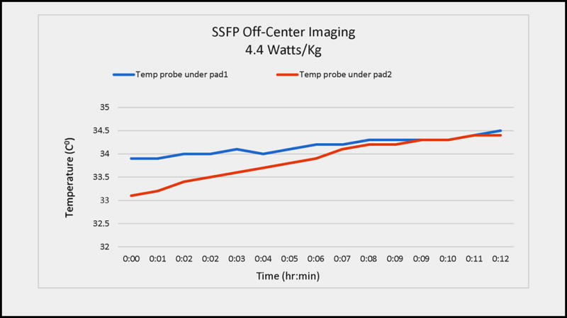
Radio-frequency heating during imaging in a swine model. The swine’s head was placed at magnet iso-center and the torso moved laterally (left-right), in order to maximize the electric field (from radio-frequency pulses transmitted by the MRI’s body coil) which is induced onto the defibrillation pads and cables, which are found at +20 cm Superior-Inferior and +15 cm Left-Right. An SSFP sequence with 4.4. W/kg SAR was used. The blue and red graphs denote temperatures recorded underneath the two defibrillation pads (between the pads and the skin). The red curve shows pad2, which leant against the MRI bore wall (e.g. the most extreme off-center situation) and consequently demonstrated the largest temperature variation.
Swine Fibrillation and Defibrillation experiments
During experiments performed in the animal fluoroscopy lab (Figure 4), the modified defibrillator system chassis (generator and low-pass filter) was placed on a table ~1.5 m from the swine table, while the fibrillation apparatus was placed on the fluoroscopy table. Stimulation from the apparatus produced ventricular fibrillation (VF), which was reversed with either a single (n=1) or two repeated (n=1) defibrillation pulses. The Zoll Medical generator’s ECG display recorded the cardiac events and recovery properly (Figure 4B).
Figure 4.

Swine testing of the MRI-conditional defibrillation system in an animal fluoroscopy lab demonstrating its utility in a non-MRI environment. (A) Photograph of the swine on the table, with red arrows pointing to the location of the defibrillation pads on the chest, as well as the fibrillation generator, which was used to induce the cardiac arrest. (B) Display of the Zoll Medical generator at two points during the experiment (i) during cardiac arrest (VF) and (ii) a few seconds after defibrillation.
During experiments performed within the MRI suite (Figure 5A), the modified defibrillator system chassis was placed on the right side of the MRI magnet, ~1.5 meters from the front of the MRI’s gantry. At this distance, it was easy to operate the M-series generator, and there was no magnetic attraction of the chassis. Fibrillation inside the MRI scanner resulted in VF (Figure 5B), which was reversed with a single defibrillation pulse in each of the four animals studied. The Zoll Medical generator single-lead ECG display did not properly record the VF event, as it was obscured by large gradient induced voltage overlays on the ECG trace during imaging32, 33, but this was noted properly using the MRI-compatible hemodynamic display (Figure 5C), allowing for the timely delivery of defibrillation. This 100% success rate, although obtained from a small sample set, is equivalent to that reported for defibrillation following electrically-induced fibrillation using conventional defibrillator systems, when there is <1 min delay post-VF28.
Figure 5.
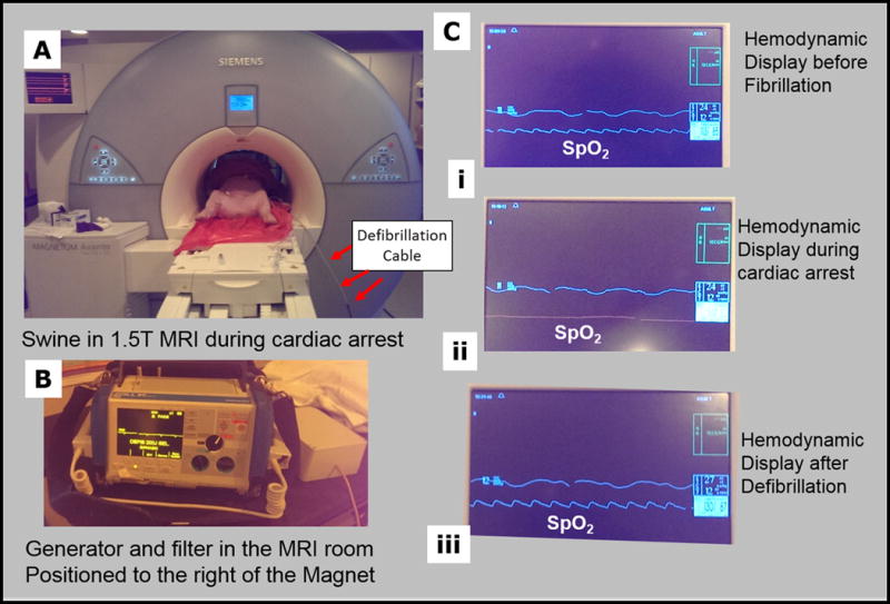
Swine testing of the MRI-conditional defibrillation system in a 1.5 T MRI. (A) Photograph of the swine inside the MRI scanner, with red arrows pointing to the defibrillation cables, as they enter the scanner. (B) Display of the Zoll Medical generator during the experiment. The generator’s ECG display was unreliable, due to sizeable Gradient-Induced-Voltage overlays on the traces. (C) Display of the MRI-compatible hemodynamic display (i) before fibrillation, (ii) during cardiac arrest (VF), and (iii) a few seconds after defibrillation. The middle, SPO2, trace is indicative of the state of the animal, and here is used as a surrogate to a reliable ECG trace.
During defibrillation in the x-ray suite and inside the MRI, heavy swine torsos were elevated by ~0.10 m. This did not result in any damage to the MRI scanner, the imaging coils, or the defibrillation apparatus.
DISCUSSION
We demonstrated that an MRI-conditional defibrillation unit could be constructed by modifying a commercial defibrillation system. None of the features or capabilities of the commercial defibrillator were sacrificed by the modifications performed. The modified system did not significantly reduce the MRI scanner’s imaging SNR, nor did it’s cabling and pads produce heating. As a result, we feel that it can be both safe and effective for use during MRI imaging and MRI-guided intervention.
Although not explored in the present study, the system we developed can also be used to perform temporary external transcutaneous pacing of the heart. This will be investigated in future studies since it will further increase the utility of the system.
The swine’s elevation (“jump”) during defibrillation did not damage the scanner, nor did it injure the subject. We used a “wide-bore” 0.7 m patient-bore MRI for these experiments, whereas most current scanners have a 0.6 m patient-bore. On the other hand, swine dimensions and weight are smaller than most patients. Further investigation is therefore required to determine if it is preferable to perform defibrillation within the bore, or more prudent to withdraw subjects from the bore and defibrillate on the MRI table, to facilitate performance of CPR. An additional solution to in-bore defibrillation is to employ dedicated defibrillation protocols, with changes in pulse profiles or electrode configurations, which greatly reduce muscle contractions34, 35.
The differences between the system SNR under battery and line-power operation point to the sources of the residual noise. It mainly originates from RFI emission through the power cable, which we are currently engaged in removing, with a smaller contribution from radiation from the chassis, which we are also addressing.
Some sites performing interventional procedures may prefer to use other defibrillation electrodes, such as radio-translucent electrodes, or those made by other vendors. Each of these electrodes will need to be examined to determine if (i) they are ferrous or create large susceptibility artifacts, (ii) they support RF eddy-currents, and (iii) heat beyond regulatory limits during high SAR imaging. RF heating of electrodes can be further reduced by cutting paths into the electrodes and thus reducing RF eddy currents36. We have also not explored possible issues with pediatric patients, for which (i) the Lorentz forces may play a larger role, and (ii) special RF heating models are needed. Additional theoretical and in vitro thermal tests may be required prior to regulatory approval.
The generator’s chassis was slightly magnetic, and this might be addressed by (a) chaining the generator to the wall so that it could not be inadvertently brought closer to the MRI, or (b) by removing the magnetic components in the generator chassis, which requires redesign of the high-voltage stages of the generator.
Additionally, the generator’s ECG display did not properly display ECG traces within the MRI. This may preferably be addressed by linking the generator to an MRI-conditional ECG system27. We consider use of such a system a necessity, since the gradient induced voltages (GIVs) during MRI scans are of the order of volts32, completely masking the real ECG, so the GIVs must be removed in order to obtain reliable ECG traces33. This system will also serve as a reliable alarm, notifying the user of a cardiac event at an earlier stage, should it occur inside the MRI. The Zoll system supports such a connection. It is important that this ECG system be able to sustain the defibrillation pulses, in terms of (i) preventing the large voltages from damaging the ECG system’s front-end, (ii) preventing large currents from propagating on the ECG leads, which can present a heating risk, and (iii) reduce the effectiveness of the defibrillation.
Availability of this external defibrillation system to the larger clinical community will require obtaining regulatory approval, which will require performing more extensive testing. We are attempting to find a commercial entity that will undertake this process. In addition, we plan to make adjustments to the defibrillator (such as to the Baluns) to enable it to be used at other MRI field strengths.
CONCLUSION
An MRI-conditional external defibrillator was constructed and validated. MRI-conditional defibrillators may permit the diagnosis and treatment of higher-risk patient populations within MRI scanners, significantly improving the patient-care options for these patients.
Supplementary Material
Clinical Perspective.
Large populations of patients are currently excluded from cardiac MRI imaging or MRI-guided surgical interventions due to the lack of equipment that can rapidly treat a cardiac event, if it occurs inside the MRI. In this study an external defibrillator, which is MRI-compatible, was developed and validated for the resuscitation of subjects that had incurred heart attacks inside the MRI scanner or in the MRI suite. Availability of this defibrillator will permit use of MR imaging and MRI-guided interventional procedures to diagnose or treat severely ill patients for symptoms for which MRI holds distinct clinical benefits. In addition, such a defibrillator is essential to the emergence of MRI-guided treatment of cardiac arrhythmia (atrial fibrillation, ventricular tachycardia) disorders.
Acknowledgments
SOURCES OF FUNDING
NIH U41-RR019703, AHA 10SDG261039, NIH R03-EB013873-01, NIH U54-HL119145, NIH R01-HL094610
Footnotes
DISCLOSURES
None.
References
- 1.Schellinger PD, Bryan RN, Caplan LR, Detre JA, Edelman RR, Jaigobin C, Kidwell CS, Mohr JP, Sloan M, Sorensen AG, Warach S, Therapeutics, Technology Assessment Subcommittee of the American Academy of N Evidence-based guideline: The role of diffusion and perfusion mri for the diagnosis of acute ischemic stroke: Report of the therapeutics and technology assessment subcommittee of the american academy of neurology. Neurology. 2010;75:177–185. doi: 10.1212/WNL.0b013e3181e7c9dd. [DOI] [PMC free article] [PubMed] [Google Scholar]
- 2.Gupta R, Mittal P, Sandhu P, Saggar K, Gupta K. Correlation of qualitative and quantitative mri parameters with neurological status: A prospective study on patients with spinal trauma. Journal of clinical and diagnostic research: JCDR. 2014;8:RC13–17. doi: 10.7860/JCDR/2014/9471.5181. [DOI] [PMC free article] [PubMed] [Google Scholar]
- 3.Swart NM, van Oudenaarde KK, Algra PR, Bindels PJ, van den Hout WB, Koes BW, Nelissen RG, Verhaar JA, Bloem HJ, Bierma-Zeinstra SM, Reijnierse MM, Luijsterburg PA. Efficacy of mri in primary care for patients with knee complaints due to trauma: Protocol of a randomised controlled non-inferiority trial (tackle trial) BMC musculoskeletal disorders. 2014;15:63–78. doi: 10.1186/1471-2474-15-63. [DOI] [PMC free article] [PubMed] [Google Scholar]
- 4.Korley FK, Pham JC, Kirsch TD. Use of advanced radiology during visits to us emergency departments for injury-related conditions, 1998–2007. JAMA: the journal of the American Medical Association. 2010;304:1465–1471. doi: 10.1001/jama.2010.1408. [DOI] [PMC free article] [PubMed] [Google Scholar]
- 5.Saber Tehrani AS, Coughlan D, Hsieh YH, Mantokoudis G, Korley FK, Kerber KA, Frick KD, Newman-Toker DE. Rising annual costs of dizziness presentations to u.S. Emergency departments. Academic emergency medicine: official journal of the Society for Academic Emergency Medicine. 2013;20:689–696. doi: 10.1111/acem.12168. [DOI] [PubMed] [Google Scholar]
- 6.Cury RC, Shash K, Nagurney JT, Rosito G, Shapiro MD, Nomura CH, Abbara S, Bamberg F, Ferencik M, Schmidt EJ, Brown DF, Hoffmann U, Brady TJ. Cardiac magnetic resonance with t2-weighted imaging improves detection of patients with acute coronary syndrome in the emergency department. Circulation. 2008;118:837–844. doi: 10.1161/CIRCULATIONAHA.107.740597. [DOI] [PubMed] [Google Scholar]
- 7.Payne AR, Casey M, McClure J, McGeoch R, Murphy A, Woodward R, Saul A, Bi X, Zuehlsdorff S, Oldroyd KG, Tzemos N, Berry C. Bright-blood t2-weighted mri has higher diagnostic accuracy than dark-blood short tau inversion recovery mri for detection of acute myocardial infarction and for assessment of the ischemic area at risk and myocardial salvage. Circulation Cardiovascular imaging. 2011;4:210–219. doi: 10.1161/CIRCIMAGING.110.960450. [DOI] [PubMed] [Google Scholar]
- 8.Chung SY, Lee KY, Chun EJ, Lee WW, Park EK, Chang HJ, Choi SI. Comparison of stress perfusion mri and spect for detection of myocardial ischemia in patients with angiographically proven three-vessel coronary artery disease. AJR American journal of roentgenology. 2010;195:356–362. doi: 10.2214/AJR.08.1839. [DOI] [PubMed] [Google Scholar]
- 9.Foster EL, Arnold JW, Jekic M, Bender JA, Balasubramanian V, Thavendiranathan P, Dickerson JA, Raman SV, Simonetti OP. Mr-compatible treadmill for exercise stress cardiac magnetic resonance imaging. Magnetic resonance in medicine: official journal of the Society of Magnetic Resonance in Medicine/Society of Magnetic Resonance in Medicine. 2012;67:880–889. doi: 10.1002/mrm.23059. [DOI] [PMC free article] [PubMed] [Google Scholar]
- 10.Vogel-Claussen J, Skrok J, Dombroski D, Shea SM, Shapiro EP, Bohlman M, Lorenz CH, Lima JA, Bluemke DA. Comprehensive adenosine stress perfusion mri defines the etiology of chest pain in the emergency room: Comparison with nuclear stress test. Journal of magnetic resonance imaging: JMRI. 2009;30:753–762. doi: 10.1002/jmri.21899. [DOI] [PMC free article] [PubMed] [Google Scholar]
- 11.Kumar A, Friedrich MG. Acute chest pain syndrome: Will mri shake up cardiovascular care in the emergency room? Expert review of cardiovascular therapy. 2007;5:139–141. doi: 10.1586/14779072.5.2.139. [DOI] [PubMed] [Google Scholar]
- 12.Foroglou N, Zamani A, Black P. Intra-operative mri (iop-mr) for brain tumour surgery. British journal of neurosurgery. 2009;23:14–22. doi: 10.1080/02688690802610587. [DOI] [PubMed] [Google Scholar]
- 13.Sonntag VK. Navigation and mri during surgery: Spine advances. World neurosurgery. 2012;78:76–77. doi: 10.1016/j.wneu.2011.10.025. [DOI] [PubMed] [Google Scholar]
- 14.Tuncali K, Morrison PR, Tatli S, Silverman SG. Mri-guided percutaneous cryoablation of renal tumors: Use of external manual displacement of adjacent bowel loops. European journal of radiology. 2006;59:198–202. doi: 10.1016/j.ejrad.2006.04.013. [DOI] [PubMed] [Google Scholar]
- 15.Schimmoller L, Blondin D, Arsov C, Rabenalt R, Albers P, Antoch G, Quentin M. Mri-guided in-bore biopsy: Differences between prostate cancer detection and localization in primary and secondary biopsy settings. AJR American journal of roentgenology. 2016;206:92–99. doi: 10.2214/AJR.15.14579. [DOI] [PubMed] [Google Scholar]
- 16.Dickfeld T, Kato R, Zviman M, Nazarian S, Dong J, Ashikaga H, Lardo AC, Berger RD, Calkins H, Halperin H. Characterization of acute and subacute radiofrequency ablation lesions with nonenhanced magnetic resonance imaging. Heart rhythm: the official journal of the Heart Rhythm Society. 2007;4:208–214. doi: 10.1016/j.hrthm.2006.10.019. [DOI] [PMC free article] [PubMed] [Google Scholar]
- 17.Kholmovski EG, Coulombe N, Silvernagel J, Angel N, Parker D, MacLeod R, Marrouche N, Ranjan R. Real time mri guided cardiac cryo-ablation: A feasibility study. Journal of cardiovascular electrophysiology. 2016;27:602–608. doi: 10.1111/jce.12950. [DOI] [PMC free article] [PubMed] [Google Scholar]
- 18.Rogers T, Lederman RJ. Interventional cmr: Clinical applications and future directions. Current cardiology reports. 2015;17:31–42. doi: 10.1007/s11886-015-0580-1. [DOI] [PMC free article] [PubMed] [Google Scholar]
- 19.Eitel C, Hindricks G, Grothoff M, Gutberlet M, Sommer P. Catheter ablation guided by real-time mri. Current cardiology reports. 2014;16:511–528. doi: 10.1007/s11886-014-0511-6. [DOI] [PubMed] [Google Scholar]
- 20.Nordbeck P, Quick HH, Bauer WR, Ertl G, Ladd ME, Ritter O. Initial clinical application of real-time mr imaging-guided ablation of cardiac arrhythmia in patients with atrial flutter. Radiology. 2014;273:310–311. doi: 10.1148/radiol.14140686. [DOI] [PubMed] [Google Scholar]
- 21.Nazarian S, Kolandaivelu A, Zviman MM, Meininger GR, Kato R, Susil RC, Roguin A, Dickfeld TL, Ashikaga H, Calkins H, Berger RD, Bluemke DA, Lardo AC, Halperin HR. Feasibility of real-time magnetic resonance imaging for catheter guidance in electrophysiology studies. Circulation. 2008;118:223–229. doi: 10.1161/CIRCULATIONAHA.107.742452. [DOI] [PMC free article] [PubMed] [Google Scholar]
- 22.American College of Cardiology Foundation Task Force on Expert Consensus D. Hundley WG, Bluemke DA, Finn JP, Flamm SD, Fogel MA, Friedrich MG, Ho VB, Jerosch-Herold M, Kramer CM, Manning WJ, Patel M, Pohost GM, Stillman AE, White RD, Woodard PK. Accf/acr/aha/nasci/scmr 2010 expert consensus document on cardiovascular magnetic resonance: A report of the american college of cardiology foundation task force on expert consensus documents. Circulation. 2010;121:2462–2508. doi: 10.1161/CIR.0b013e3181d44a8f. [DOI] [PMC free article] [PubMed] [Google Scholar]
- 23.Expert Panel on MRS. Kanal E, Barkovich AJ, Bell C, Borgstede JP, Bradley WG, Jr, Froelich JW, Gimbel JR, Gosbee JW, Kuhni-Kaminski E, Larson PA, Lester JW, Jr, Nyenhuis J, Schaefer DJ, Sebek EA, Weinreb J, Wilkoff BL, Woods TO, Lucey L, Hernandez D. Acr guidance document on mr safe practices: 2013. Journal of magnetic resonance imaging: JMRI. 2013;37:501–530. doi: 10.1002/jmri.24011. [DOI] [PubMed] [Google Scholar]
- 24.Nazarian S, Beinart R, Halperin HR. Magnetic resonance imaging and implantable devices. Circulation Arrhythmia and electrophysiology. 2013;6:419–428. doi: 10.1161/CIRCEP.113.000116. [DOI] [PubMed] [Google Scholar]
- 25.Van Sonnenberg E. ACR–SIR–SPR practice parameter for the performance of image-guided percutaneous needle biopsy (PNB) American Congress of Radiology Publication. 2014 [Google Scholar]
- 26.Antman EM, Anbe DT, Armstrong PW, Bates ER, Green LA, Hand M, Hochman JS, Krumholz HM, Kushner FG, Lamas GA, Mullany CJ, Ornato JP, Pearle DL, Sloan MA, Smith SC, Jr, Alpert JS, Anderson JL, Faxon DP, Fuster V, Gibbons RJ, Gregoratos G, Halperin JL, Hiratzka LF, Hunt SA, Jacobs AK, American College of C, American Heart Association Task Force on Practice G, Canadian Cardiovascular S ACC/AHA guidelines for the management of patients with st-elevation myocardial infarction: A report of the american college of cardiology/american heart association task force on practice guidelines (committee to revise the 1999 guidelines for the management of patients with acute myocardial infarction) Circulation. 2004;110:e82–292. [PubMed] [Google Scholar]
- 27.Tse ZT, Dumoulin CL, Clifford GD, Schweitzer J, Qin L, Oster J, Jerosch-Herold M, Kwong RY, Michaud G, Stevenson WG, Schmidt EJ. A 1.5t mri-conditional 12-lead electrocardiogram for mri and intra-mr intervention. Magnetic resonance in medicine: official journal of the Society of Magnetic Resonance in Medicine/Society of Magnetic Resonance in Medicine. 2014;71:1336–1347. doi: 10.1002/mrm.24744. [DOI] [PMC free article] [PubMed] [Google Scholar]
- 28.Kroll MW, Fish RM, Calkins H, Halperin H, Lakkireddy D, Panescu D. Defibrillation success rates for electrically-induced fibrillation: Hair of the dog. Conference proceedings: Annual International Conference of the IEEE Engineering in Medicine and Biology Society. IEEE Engineering in Medicine and Biology Society. Conference. 2012;2012:689–693. doi: 10.1109/EMBC.2012.6346025. [DOI] [PubMed] [Google Scholar]
- 29.IEC. IEC 60601-2-33 medical electrical equipment–part 2–33: Particular requirements for the safety of magnetic resonance equipment for medical diagnosis 2013
- 30.International ASTM. Standard practice for marking medical devices and other items for safety in the magnetic resonance environment. ASTM f2503 - 13. 2014 doi: 10.6009/jjrt.2018_JSRT_74.7.739. [DOI] [PubMed] [Google Scholar]
- 31.Seeber DA, Jevtic J, Menon A. Floating shield current suppression trap. Concepts in Magnetic Resonance Part B (Magnetic Resonance Engineering) 2004;21B:26–31. [Google Scholar]
- 32.Bencsik M, Bowtell R, Bowley R. Electric fields induced in the human body by time-varying magnetic field gradients in mri: Numerical calculations and correlation analysis. Physics in medicine and biology. 2007;52:2337–2353. doi: 10.1088/0031-9155/52/9/001. [DOI] [PubMed] [Google Scholar]
- 33.Zhang SH, Tse ZT, Dumoulin CL, Kwong RY, Stevenson WG, Watkins R, Ward J, Wang W, Schmidt EJ. Gradient-induced voltages on 12-lead ecgs during high duty-cycle mri sequences and a method for their removal considering linear and concomitant gradient terms. Magnetic resonance in medicine: official journal of the Society of Magnetic Resonance in Medicine/Society of Magnetic Resonance in Medicine. 2016;75:2204–2216. doi: 10.1002/mrm.25810. [DOI] [PMC free article] [PubMed] [Google Scholar]
- 34.Janardhan AH, Gutbrod SR, Li W, Lang D, Schuessler RB, Efimov IR. Multistage electrotherapy delivered through chronically-implanted leads terminates atrial fibrillation with lower energy than a single biphasic shock. Journal of the American College of Cardiology. 2014;63:40–48. doi: 10.1016/j.jacc.2013.07.098. [DOI] [PMC free article] [PubMed] [Google Scholar]
- 35.Kolandaivelu A, Jayanti V, Halperin HR, Berger RD. Switchable faraday shielding with application to reducing the pain of internal cardiac defibrillation while permitting external defibrillation. IEEE transactions on bio-medical engineering. 2012;59:409–416. doi: 10.1109/TBME.2011.2173687. [DOI] [PubMed] [Google Scholar]
- 36.Schmidt EJ, Tse ZT, Reichlin TR, Michaud GF, Watkins RD, Butts-Pauly K, Kwong RY, Stevenson W, Schweitzer J, Byrd I, Dumoulin CL. Voltage-based device tracking in a 1.5 tesla mri during imaging: Initial validation in swine models. Magnetic resonance in medicine: official journal of the Society of Magnetic Resonance in Medicine/Society of Magnetic Resonance in Medicine. 2014;71:1197–1209. doi: 10.1002/mrm.24742. [DOI] [PMC free article] [PubMed] [Google Scholar]
Associated Data
This section collects any data citations, data availability statements, or supplementary materials included in this article.