Significance
Bioresorbable vascular scaffolds (BVSs) are poised to replace permanent metal stents for the treatment of coronary heart disease (CHD), which claims over 7 million lives each year. BVSs support the artery for 6 mo but completely dissolve in 2 y, eliminating serious long-term complications. The first clinically approved BVS is made from a brittle material, poly (l-lactide) (PLLA), yet it does not fracture during crimping or deployment. We used X-ray microdiffraction to discover multiple, micron-scale morphologies in the crimped BVS, which confer ductility to PLLA and resist fracture upon deployment. Contrary to intuition, the crimping process enhances scaffold strength, a result that researchers should keep in mind when designing thinner scaffolds to make BVSs broadly applicable to CHD.
Keywords: structural transformation, ductility, poly (l-lactide), coronary heart disease, microdiffraction
Abstract
Poly(l-lactide) (PLLA) is the structural material of the first clinically approved bioresorbable vascular scaffold (BVS), a promising alternative to permanent metal stents for treatment of coronary heart disease. BVSs are transient implants that support the occluded artery for 6 mo and are completely resorbed in 2 y. Clinical trials of BVSs report restoration of arterial vasomotion and elimination of serious complications such as late stent thrombosis. It is remarkable that a scaffold made from PLLA, known as a brittle polymer, does not fracture when crimped onto a balloon catheter or during deployment in the artery. We used X-ray microdiffraction to discover how PLLA acquired ductile character and found that the crimping process creates localized regions of extreme anisotropy; PLLA chains in the scaffold change orientation from the hoop direction to the radial direction on micrometer-scale distances. This multiplicity of morphologies in the crimped scaffold works in tandem to enable a low-stress response during deployment, which avoids fracture of the PLLA hoops and leaves them with the strength needed to support the artery. Thus, the transformations of the semicrystalline PLLA microstructure during crimping explain the unexpected strength and ductility of the current BVS and point the way to thinner resorbable scaffolds in the future.
Cardiovascular disease (CVD) claims over 15 million lives per year—more lives than communicable, maternal, neonatal, and nutritional disorders combined and more than twice the number of deaths due to all cancers (1). Coronary heart disease (CHD), the narrowing of coronary arteries due to the deposition of plaque, accounts for nearly 50% of all CVD deaths (1). To restore blood flow, most patients receive minimally invasive balloon angioplasty followed by stent implantation (1 million in 2008 in the United States) (2). Stents are metal mesh tubes that are delivered to the target lesion while they are crimped onto a balloon. Once they are positioned at the lesion, inflation of the balloon compresses the plaque against the vessel wall and deploys the stent to provide support at the enlarged diameter after the balloon is deflated and withdrawn. Metal stents are permanent, and their stiffness prohibits vasomotion and dilation (3, 4). Further, they present a lifelong risk of late stent thrombosis (3–6). A new technology is poised to displace metal stents: bioresorbable vascular scaffolds (BVS), which have been deemed the “fourth revolution” in percutaneous coronary intervention (7, 8).
The goal of tissue scaffolds is to restore the healthy state of the tissue, rather than merely ameliorating the diseased state (9–11). Poly(l-lactide) (PLLA) was selected as the material for BVS because its semicrystalline structure gives it adequate radial strength [>300 mm Hg (12)], and it degrades into products that are metabolized by the human body (13–16). Clinically, bioresorption of PLLA vascular scaffolds occurs within 2–3 y, and the treated segment of the coronary artery is restored in terms of vasomotion and vasoresponse (17–19). Success of a BVS depends on its ability to withstand deformation during both crimping onto the balloon and deployment at the lesion and still have sufficient strength to hold the artery open for 6 mo or more. Achieving this with PLLA is remarkable in view of the literature, which describes PLLA as a brittle material with a fracture strain ranging from 5 to 13% at temperatures below 30 °C (20–22). Scaffold deployment in the arteries occurs in aqueous media, for which the scant literature reports a strain at break of PLLA less than 10% (23). The usual approaches to overcoming the tendency of PLLA to fracture, blending (24, 25) and copolymerization (26–28), are not acceptable for BVSs because they reduce the lifetime of the polymer in the body (28, 29). Therefore, the material (pure PLLA) at the heart of the first clinically approved vascular scaffold [European Conformity (CE Mark) in 2011 (4) and US Food and Drug Administration (FDA) approval in July 2016 (30)] is notorious for being brittle.
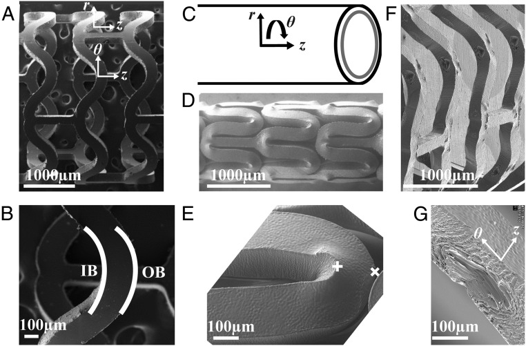
The processes for production and implantation for both stents and scaffolds appear superficially similar: tube formation, laser-cutting of the strut lattice, crimping, and deployment (8). However, the strain fields and their effect on material structure and properties are dramatically different. PLLA scaffolds (∼150 μm thick) (8) are thicker than metal stents (∼80 μm) (31) due to the lower stiffness and mechanical strength of polymers relative to metals. As a result, greater strains are encountered during crimping and deployment of polymeric scaffolds. For example, elongation at the outer bend (OB; Fig. 1B) of a U crest during crimping can be as high as 50% in the θ direction (Fig. S1). This solid-state deformation of the as-cut PLLA scaffold (Fig. 1A) is performed near its glass transition (Tg ∼ 60–65 °C), where its properties depend strongly on temperature (22) and accurate, predictive models are not yet available. Furthermore, the effect of processing strain on the semicrystalline microstructure of a polymer is crucial for understanding its performance, but modeling deformation-induced morphology in semicrystalline polymers is a persistent challenge (32). Therefore, direct observations of changes in semicrystalline morphology caused by deformation are needed, and the inhomogeneous strain field imposed on the BVS during crimping demands investigation by a technique that offers micron-scale resolution. Recent advances in X-ray microdiffraction (33) meet this need and provide results that reveal the basis of the balance of ductility and strength that enables PLLA vascular scaffolds: crimping creates a multiplicity of materials from a single one—with strong and ductile regions arranged favorably for deployment.
Fig. 1.
SEMs of the subassemblies (as-cut, crimped, and deployed) of a PLLA vascular scaffold. The expanded tube is laser-cut to create an (A) as-cut scaffold. (B) The U crest of an as-cut scaffold indicating the IB and OB. (C) Cylindrical coordinate system for the scaffold. (D) Crimped scaffold. (E) A U crest of a crimped scaffold in D. (F) Deployed scaffold. (G) Diamond-shaped voids present in a deployed U crest.
Fig. S1.
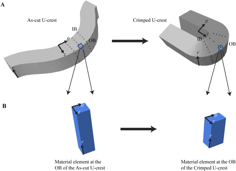
Estimating the strain field created during crimping. (A) Visualizing the strain field with an array of material points (black dots). (Left) As-cut U crest. (Right) Crimped U crest. (B) Estimating the elongation at the OB along the θ direction. (Left) An infinitesimally small volume element at the OB of the as-cut scaffold. (Right) The same volume element in the crimped state, here illustrated with the z dimension unchanged and showing that the r dimension decreases by 33% during crimping (based on unpublished SEM images).
Results
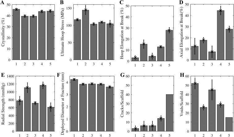
During the development of PLLA scaffolds, the relationship between the conditions used to produce the expanded tube, before laser cutting, and the properties of the resulting scaffold were investigated. An extruded PLLA preform was subjected to a biaxial elongation during tube expansion, and the relationship of hoop elongation and axial elongation (Table S1) to mechanical properties (Fig. S2) was measured. Surprisingly, group 5 (200% hoop and 200% axial elongation; Table S1), the most ductile tube (elongation at break >25% in both the hoop and axial directions; Fig. S2 C and D), did not perform well upon deployment [deployment diameter at which fracture began was only ∼3.6 mm (Fig. S2F) and had the largest number of fractured elements upon reaching that diameter, >40 per scaffold; Fig. S2G]. Similarly, the expanded tube with the second best mechanical properties (group 4, hoop elongation to break ∼15% and axial elongation to break ∼45%; Fig. S2 C and D) also fractured upon deployment (∼15 cracks per scaffold; Fig. S2G). Contrary to expectation, expanded tubes with inferior mechanical properties (groups 1–3; Table S1) gave superior structural integrity where it counts—upon deployment (fewer than five cracks per scaffold; Fig. S2G). To our knowledge, no explanation of this surprising finding has ever been offered.
Table S1.
Expanded PLLA tubes, grouped by the axial and radial deformation during tube expansion
| Group | Extruded ID, mm | Extruded OD, mm | Expanded ID, mm | Expanded OD, mm | OD strain, % | ID strain, % | Axial strain, % |
| 1 | 0.53 | 1.65 | 3.20 | 3.50 | 112 | 500 | 20 |
| 2 | 0.53 | 2.53 | 3.20 | 3.50 | 38 | 500 | 200 |
| 3 | 0.64 | 1.69 | 3.20 | 3.50 | 107 | 400 | 20 |
| 4 | 0.80 | 2.17 | 3.20 | 3.50 | 61 | 300 | 100 |
| 5 | 1.07 | 2.69 | 3.20 | 3.50 | 30 | 200 | 200 |
Fig. S2.
Mechanical properties of expanded tubes (A–D) and deployed scaffolds (E–H) for groups given in Table S1. Apparent crystallinity (A) inferred from DSC thermograms (n = 15). Ultimate stress at fracture (B) and the elongation at break (C) for notched dog bone specimens laser-cut with long axis of the dog bone oriented along the hoop direction of the expanded tube (n = 15). Elongation at break (D) for notched dog bone specimens laser-cut with long axis of the dog bone oriented along the axial direction of the expanded tube (n = 15). Crimped scaffolds made from expanded tubes using identical laser-cutting and crimping conditions were tested to failure upon deployment. The radial strength (E) of scaffolds deployed to 3.5-mm diameter (n = 5) is measured under a compressive radial load that is increased until fracture occurs (MSI RX650 Radial Force Testing Instrument). Scaffolds were deliberately overdilated to evaluate the deployed diameter at fracture (F, n = 5). For specimens that survive to a deployed diameter greater than that of the expanded tube (3.5 mm), the number of cracks (G) and diamond-shaped voids (H) are presented (n = 5, except for group 5, for which only one scaffold survived to 3.5-mm diameter, so 40 represents a lower bound on cracks/scaffold). In addition to coauthors M.B.K. and J.P.O., the following Abbott technologists contributed to these experiments: Thierry Glauser, Vincent Gueriguian, Bethany Steichen, Manish Gada, and Lothar Kleiner. Figure adapted from ref. 43.
To understand the success of BVS, the present study focuses on scaffolds produced with the tube expansion conditions that are used for current clinical BVS devices (group 3; Table S1). The resulting scaffolds afford a wide margin of safety for overdilation without fracture (to ∼3.8 mm with few cracks, approximately five per scaffold; Fig. S2 F and G). The apparent contradiction between ductility of the expanded tube and the performance during deployment motivates investigation of the structural changes that occur during crimping, which reduces the diameter of the scaffold from 3.5 mm in the as-cut form (Fig. 1A) to 1.7 mm in the crimped state (Fig. 1D). Scanning electron micrographs (SEM) of crimped scaffolds show that the deformation zones are localized to areas that are ∼100 µm across (compare Fig. 1 B and E). Compression along the θ direction (defined in Fig. 1 C and G) occurs at each inner bend (IB; Fig. 1B) causing material to bulge out of the (θ, z) plane (Fig. 1E). Thus, an elongation in the r direction occurs at each inner bend, which does not occur in metal stents (Fig. S3). At each outer bend (Fig. 1B), tension along the θ direction causes the scaffold to thin in the r direction. Upon deployment (Fig. 1F), the inner bend is placed under tension, but it does not fracture, despite the brittle character associated with PLLA. Instead, a diamond-shaped void forms (Fig. 1G) (34) in the scaffold, a feature not observed in metal stents (Fig. S3).
Fig. S3.
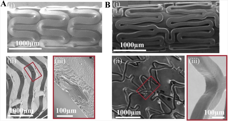
Influence of material properties on the crimped and deployed state of vascular implants. Scanning electron microscopy is used to compare a 150-µm PLLA scaffold (A) and an 80-µm cobalt–chromium (B) permanent stent (45, 46). The PLLA scaffold and Co–Cr stent are crimped (A and B, i) onto a balloon catheter and deployed (A and B, ii) to an outer diameter of 3.5 mm. The inner bends of deployed struts (A and B, iii) indicate that diamond-shaped voids are specific to PLLA scaffolds. [Fig. S3B, i–ii is reprinted with permission from ref. 45, and Fig. S3B, iii is reprinted with permission from ref. 46.]
Although prior data showed that the formation of diamond-shaped voids correlates with successful deployment without fracture (Fig. S2 G and H), no explanation of this correlation has yet been offered. Unlike cracks, diamond-shaped voids are conical cavities at the inner bends of U, W, and Y crests (Fig. S4A) that do not rupture either the outer diameter (OD) or inner diameter (ID) surface. To understand the microstructural basis of this mechanism for yielding without failure, we use X-ray microdiffraction to gain a 3D view of the morphology created during crimping and deployment. In particular, we characterize structural transformations that occur in U crests, which permit estimates of the strain imposed during crimping (Fig. S1). Relative to the original 150-μm thickness of the as-cut scaffold (Fig. 1A), the bulge at each inner bend causes an increase in thickness to ∼180 μm (position + in Fig. 1E), and the tensile deformation at the outer bend causes a decrease in thickness to ∼110 μm (position × in Fig. 1E).
Fig. S4.
Definition of terms and illustration of the part of the sample that was embedded in preparation for microtoming sections. (A) The scaffold is laser-cut to remove most of the material of the expanded PLLA tube, leaving the rings and struts that make up the scaffold. We chose to examine U crests because they capture the intense, local deformation that occurs during crimping (whereas the arms mainly reorient without deforming and struts neither reorient nor deform). The outline (34) indicates the typical size and orientation of the embedded specimen from which sections were cut. Fig. S4A reprinted with permission from ref. 34. (B) A section cut from a crimped scaffold (specifically C45; Figs. 2B and 3).
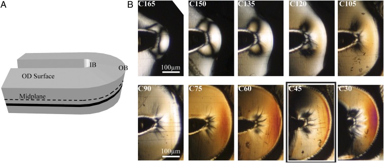
Resolution in the radial direction (r; Fig. 1C) is achieved by microtoming sections in the (θ, z) plane (Fig. 1 A and G). Moving from the OD to the ID of the scaffold (upper left to lower right in Fig. 2B), we observe a steady increase in the birefringence. A possible explanation for this trend is the gradient in both temperature and strain that is set up during tube expansion (35), before laser cutting. When hot PLLA comes into contact with a cooler outer mold, the material close to the outer diameter is quenched, which hinders crystallization near the OD. In addition, the tube expansion step imposes larger strains on material at the ID (∼400%) than at the OD (∼100%). Consequently, the material close to the ID has a greater driving force for oriented crystallization and a longer time to crystallize before vitrification, which may explain the observed gradient in birefringence.
Fig. 2.
Variation in birefringence through the thickness of a crimped PLLA vascular scaffold. (A) Schematic of a U crest (Fig. 1E) indicating the OD surface, the midplane (black dotted line), and the position of a particular section (black band). (B) Cropped polarized light micrographs of sequential 15-μm-thick microtomed sections from the OD to the ID of a crimped U crest. Sections are labeled with C to denote “crimped” and the approximate distance in microns from the inner diameter of the scaffold (i.e., C30 was closest to the scaffold’s ID, and C165 was closest to its OD). A bold rectangle indicates the section analyzed in Fig. 3.
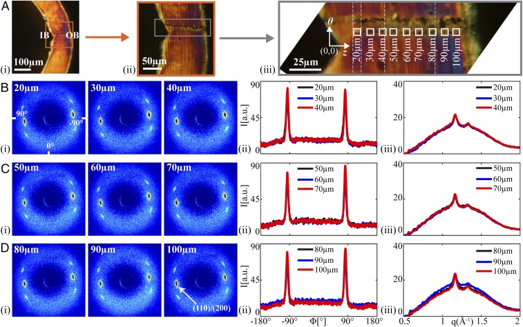
A coarse-grain map of the distribution of orientation in the (θ, z) plane, obtained using polarized light microscopy, shows craze structures at the IB and strong orientation at the OB. In contrast to the gradient in the r direction (from one section to the next in Fig. 2B), gradients of birefringence in the plane of each section must have been created by the crimping process (Fig. 1D) because the expanded tube has uniform structure in the (θ, z) plane. The compressive forces that lead to bulge formation (Fig. 1E) cause plastic deformation and crazing at the IB (black lines emanating from the cusp of the inner bend in Fig. 2B) (36). Midway between the IB and the OB, there is a relatively uniform region (orange Michel–Levy color in Fig. 2B, C45). At the outer bend, the tensile forces in the θ direction during crimping result in strong orientation (burnt orange Michel–Levy color in Fig. 2B, C45). Of particular relevance to the formation of diamond-shaped voids, section C45 contains the deepest fissures at the IB; thus, we examine C45 using microdiffraction to probe the role of crimping in the formation of diamond-shaped voids and enhancing the tensile strength of the scaffold.
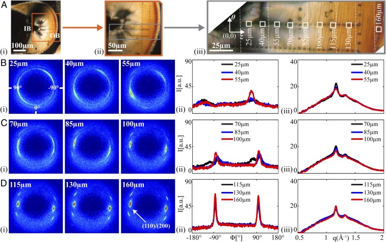
Resolution in the (θ, z) plane is achieved by translating the sample relative to the microdiffraction beam [beamline 2-ID-D of the Advanced Photon Source (APS), Argonne National Laboratory, 200-nm-diameter irradiated area], typically using 5-μm steps. The line of measurement points highlighted in Fig. 3A, iii, spans from the compression region at the IB to the tensile region at the OB. At the IB we observe striking, highly asymmetric diffraction patterns (Fig. 3B, i; 25–55 μm from the innermost edge) and complex azimuthal variation of (110)/(200) intensity (Fig. 3B, ii). We believe this is a result of the yielding that occurs under severe compression. Moving away from the IB (70–100 μm), the middle zone is characterized by progressively stronger orientation (Fig. 3C, i). Moving to the OB, the crystallites have their c axis strongly aligned parallel to the θ direction (Fig. 3D, i), giving a narrower azimuthal distribution (Fig. 3D, ii; ∼10°, Fig. S5G). Despite its reputation for being brittle, the PLLA does not fracture under the tension at the OB during crimping; instead, the structure transforms to one with orientation parallel to the OB and, thus, gains tensile strength. The yielding and restructuring in the compact zone near the inner bend (0–85 μm; Fig. 3B) preserve the integrity of the rest of the material (100–160 μm; Fig. 3D) during crimping.
Fig. 3.
Structural characterization of a crimped U section (C45, bold rectangle in Fig. 2B). (A) Polarized light micrographs of C45 with increasing magnification from A, i, to provide context relative to the IB and OB, to (A, iii) a composite image (vertical dotted lines mark transitions between images) that shows positions of microdiffraction acquisitions (marked using the X-ray beam). Squares correspond to patterns shown in B–D. Microdiffraction data acquired (B) close to the IB, (C) midway between the IB and OB, and (D) close to the OB: (B–D, i) X-ray microdiffraction patterns, (B–D, ii) azimuthal intensity distribution I(ϕ) at the (110)/(200) diffraction (identified in D, i, azimuthal coordinates in (B, i, averaged over q ∈ 1.08–1.24 Å−1), and (B–D, iii) radial intensity distribution I(q) (azimuthally averaged).
Fig. S5.
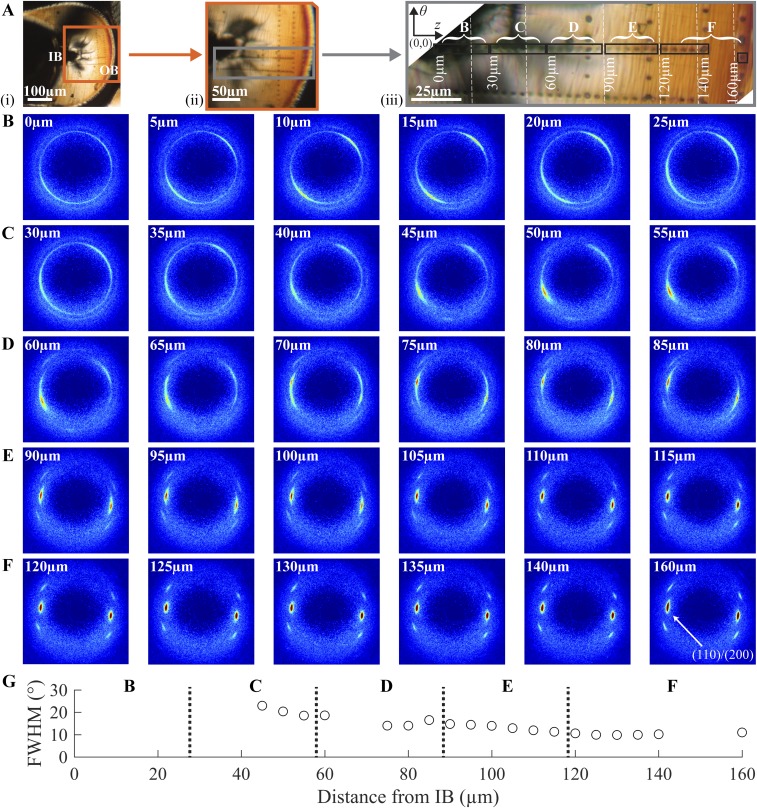
Variation in morphology from the inner bend (IB) to the outer bend (OB) of the C45 crimped U section. (A) Polarized light images of the C45 crimped section (higher magnification image comprises multiple images stitched together at vertical white dashed lines). (B–F) Diffraction patterns acquired at the positions of the corresponding burn marks in A. The (110)/(200) peaks are indicated in F (160 μm). (G) The azimuthal full width at half maximum (FWHM) for the (110)/(200) peaks of the diffraction patterns serves as a measure of the strength of orientation of the crystallites. Note that values are not given for patterns acquired near the IB, where the polymer chains tilt out of plane and the azimuthal spread becomes increasingly broad (B and C), making it difficult to identify distinct peaks.
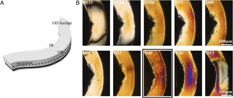
To mimic deployment of a scaffold in an artery, a crimped scaffold is immersed for two minutes in phosphate-buffered saline (PBS) at 37 °C and then radially expanded by inflation of a balloon. The radial sequence of sections (Fig. 4B) shows notches at the inner bend corresponding to the diamond-shaped void that forms upon deployment (Fig. 1 F–G): the notch is deepest near the midplane (D80 and D93; Fig. 4B). The birefringence in the deployed sections is higher than that seen in the crimped sections (compare Fig. 2B to Fig. 4B). Microdiffraction analysis was performed on section D40, similar to the r position of section C45 above.
Fig. 4.
Variation in birefringence through the thickness of a deployed PLLA vascular scaffold. (A) Schematic of a U crest (Fig. 1G) indicating the OD surface, the midplane (black dotted line), and the position of a particular section (black band). (B) Cropped polarized light micrographs of sequential 15-μm-thick microtomed sections from the OD to the ID of a deployed U crest. Sections are labeled with D to denote “deployed” and the approximate distance in microns from the inner diameter of the scaffold (i.e., D13 was closest to the ID of the scaffold, and D133 was closest to its OD). A bold rectangle indicates the section analyzed in Fig. 5.
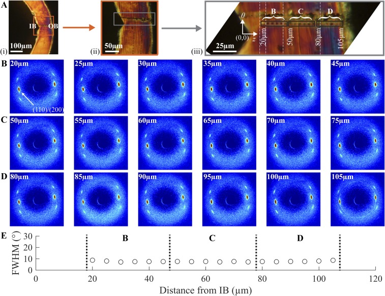
The 2D scattering patterns are remarkably similar at all positions from IB to OB (Fig. 5 B–D, i). The intensity and azimuthal breadth of the (110)/(200) diffraction peaks (Fig. 5 B–D, ii) and the relative magnitude of the crystalline diffraction to the amorphous scattering (Fig. 5 B–D, iii) hardly vary along the path from IB to OB. In contrast to the dramatic variations in structure in the crimped state (Figs. 2 and 3 and Fig. S5), the deployed state is remarkably uniform (Figs. 4 and 5 and Fig. S6). During deployment, the IB is placed under tension, and a diamond-shaped void is observed. In the vicinity of the void, there is no evidence of fissures or yielding; there are no craze fibrils crossing the diamond-shaped void, nor any crazing near it. Deployment places the OB under compression, yet again there are no indications of yielding; the material at the OB retains the strong θ orientation (∼10°; Fig. S6E) that was seen in the crimped state. Although the formation of diamond-shaped voids might at first appear to be a defect in the scaffold, the morphology in the deployed state suggests that the gentle separation of the surfaces of the diamond-shaped void allows the material to relax into a uniform, oriented structure, consistent with mechanical integrity and radial strength in the bulk (group 3, Fig. S2 E–H). Thus, the crazing and reorientation at the inner bend produced by crimping permits the uniformity and integrity of the deployed state, explaining the previously paradoxical observation that scaffolds with a high incidence of diamond-shaped voids resist fracture upon deployment (Fig. S2 G–H).
Fig. 5.
Structural characterization of a deployed U section (D40; bold rectangle in Fig. 4B). (A) Polarized light micrographs of D40 with increasing magnification from A, i, to provide context relative to the IB and OB, to (A, iii) a composite image (vertical dotted lines mark transitions between images) that shows positions of microdiffraction acquisitions (marked using the X-ray beam). Squares correspond to patterns shown in B–D. Microdiffraction data acquired (B) close to the IB, (C) midway between the IB and OB, and (D) close to the OB: (i) X-ray microdiffraction patterns, (ii) azimuthal intensity distribution I(ϕ) at the (110)/(200) diffraction (identified in D, i, azimuthal coordinates in B, i, averaged over q ∈ 1.08–1.24 Å−1), and (iii) radial intensity distribution I(q) (azimuthally averaged).
Fig. S6.
Variation in morphology from the inner bend (IB) to the outer bend (OB) of the D40 deployed U section. (A) Polarized light images of the D40 deployed section (higher magnification image comprises multiple images stitched together at vertical white dashed lines). (B–D) Diffraction patterns acquired at the positions of the corresponding burn marks in A. The (110)/(200) peaks are indicated in B (20μm). (E) The azimuthal FWHM for the (110)/(200) peaks of the diffraction patterns serves as a measure of the strength of orientation of the crystallites.
Conclusions
The structural integrity of BVSs is of paramount importance to their clinical success (37). Scaffolds must not fracture even if overdilated during implantation and must retain their strength for 6 mo (38) to support the occluded artery. The requirement of lasting strength is the compelling advantage of pure PLLA relative to more ductile PLLA blends or copolymers. The mechanical strength of BVSs is governed by their semicrystalline microstructure, which is determined by the complex interplay of thermal and strain histories imparted during tube expansion, crimping, and deployment. Processing conditions for tube expansion must be carefully selected because the resulting microstructure influences the response of PLLA upon crimping and deployment.
The fine spatial resolution of microdiffraction data at the deformation regions of interest shows that the multiplicity of morphologies created during crimping (Fig. 3) works in tandem to enable deployment without failure. Looking back at the crimped state (Fig. 2), it is noteworthy that the birefringence in the (θ, z) plane was low at the IB, consistent with chains being oriented out of plane (along r). In semicrystalline polymers, a graceful separation of surfaces is possible when the chain axis is tangential to the surface (no chains need to be extended or broken). Thus, the reorganization of the semicrystalline structure during crimping sets the stage for formation of the diamond-shaped voids (Fig. 1G) that permit deployment with relatively little tensile stress at the IB. In turn, the low tensile stress at the IB during deployment protects the OB from high compressive stresses. The results presented in this report caution against focusing solely on the tube expansion step in the design of thinner scaffolds. Contrary to intuition, scaffolds gain strength from the crimping process because it can impart a morphology that confers ductility to a nominally brittle material.
Vascular scaffolds are designed to be as thin as possible to minimize disruption of blood flow through coronary arteries. Despite the clinical success of 150-µm-thick scaffolds, clinicians seek even thinner BVS to treat smaller and more complex arterial lesions. PLLA preforms can be expanded to a thickness comparable to that of permanent stents (∼80 µm), but they must be strong enough to resists vessel spasms (∼300 mm Hg) (12) to support the occluded artery. Concerns regarding faster degradation of thinner scaffolds are mitigated by the fact that there is negligible mass loss at 12 mo for current BVSs—twice the time required for supporting the artery (38). A thinner scaffold is expected to relieve the compression of the inner bend during crimping and reduce the out-of-plane strain; thus, the present results suggest that thinner scaffolds will have proportionately smaller diamond-shaped voids. To bring a thinner scaffold to the clinic, its hoop strength must match that of current BVSs, requiring the material to have greater strength; the present findings point to the crimping step as a key process that can increase strength in thinner BVSs, extending their benefits to a broader patient population.
Materials and Methods
Preparation of Vascular Scaffolds.
The scaffolds used for this study were produced by Abbott Vascular through a multistep procedure: pure poly(l-lactide) with a Tg between 60 and 65 °C was extruded into tubes; the extruded tubes were expanded from an outer diameter of ∼1.5 mm to an outer diameter of 3.5 mm and wall thickness of 150 μm using stretch blow molding; the scaffolds were formed from the expanded tube by laser-cutting the desired pattern of axial struts and azimuthal rings (Fig. S4A); and the scaffolds were coated with a 2- to 2.5-μm layer of amorphous poly(D,l-lactide), similar to the clinical coating except for the omission of the antiproliferative drug, crimped over a delivery balloon, and sterilized with electron beam radiation. From the same batch of crimped scaffolds used for this study, some of the scaffolds were deployed in vitro using balloon inflation in a bath of saline at physiological temperature (37 °C). Thus, the crimped and deployed scaffolds came from the same lot of PLLA and were processed under the same specifications, on the same equipment, and by the same operators. The scaffolds were stored in a −80 °C freezer to preserve material properties (i.e., prevent aging) and were taken out for sectioning. A detailed description of the scaffold manufacturing process may be found in the patent literature (39, 40).
Microtomed Sections of Crimped and Deployed Subassemblies.
Consecutive sections in the (θ, z) plane, each ∼15 µm thick, were provided by Abbott Vascular. The sections were obtained by carefully controlling the orientation of the scaffold of interest (crimped or deployed) during embedding in a clear colorless plastic methylmethacrylate-based embedding medium (Technovit 7100; Electron Microscopy Sciences) using a 120-min cure at 25 °C. The size of the specimen usually included two to three consecutive U crests (outlined in Fig. S4A), which were oriented in the embedding material such that the U crests were in a plane near the surface where the block face could be cut. The embedded sample was glued to the microtome mounting post oriented with the r direction of the sample parallel to the post axis. When placed in the microtome, the post was rotated to orient the z axis of the sample parallel to the cutting direction. Sections 15 µm thick were cut using a glass knife at −75 °C on a PowerTome XL Ultra-Microtome. The block face was cut, and excess embedding material was removed until the plane of the U crests was first exposed. Starting with the first section that contained scaffold material, consecutive sections were carefully retained and labeled in sequence order until the sections no longer contained scaffold material. A representative section from a crimped sample (Fig. S4B) shows consecutive U crests in embedding medium.
Scanning Electron Microscopy of As-Cut, Crimped, and Deployed Vascular Scaffolds.
The PLLA scaffolds were mounted on SEM sample stubs using carbon tape and then sputter coated with gold to improve conductivity during image acquisition. Images were acquired using a Zeiss 1550 VP Field Emission SEM at California Institute of Technology and a Hitachi S-4800 Field Emission Microscope at Abbott Vascular.
X-Ray Microdiffraction Measurements on 15-µm-Thick Scaffold Sections.
The hard X-ray Scanning Microprobe (HXRSM) at beamline 2-ID-D of the APS at the Argonne National Laboratory was used to acquire the microdiffraction data. The HXRSM combines microfocusing capabilities with X-ray sensitivity to measure crystallographic strain and the ability to penetrate several microns through a specimen. The HXRSM uses radiation from the high-brilliance source generated by an electron beam of 7 GeV in the APS storage ring and a 3.3-cm-period undulator. The X-ray microprobe radiation has an energy in the range of 6–20 keV. For the present experiments, X-rays with energy of 10.1 keV (λ = 1.227 Å) were used. A combination of an Si(111) monochromator and a white beam slit located 43.5 m upstream of the zone plate can achieve a minimum spot size of 0.15 μm. For our studies, a 0.2-μm beam spot size was used. Further details of the beamline optics can be found in the literature (41). A Mar165 CCD area detector at 2-ID-D was used to acquire 2D scattering patterns. The samples were mounted on an aluminum holder. Using a CeO2 standard, the q range was calibrated, and the sample-to-detector distance was measured to be 119.923 mm. A detailed description of the X-ray analysis can be found in Figs. S7–S12.
Fig. S7.
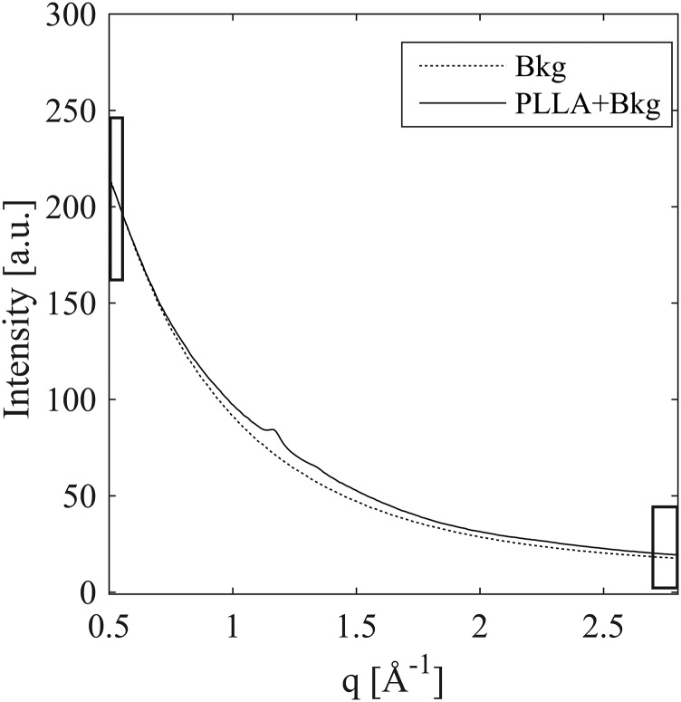
Background scattering (dashed) compared with background plus a 15-μm-thick section of poly(l-lactide) (solid). The background and the sample scattering were acquired within 7 min of each other using a 30-s acquisition. The greatest difference between the two is at the (110)/(200) diffraction peak (less than 10%), and the PLLA contribution is negligible at both low-q (0.5 < q <0.55 Å−1) and high-q (2.7 < q <2.8 Å−1), indicated by black rectangles.
Fig. S12.
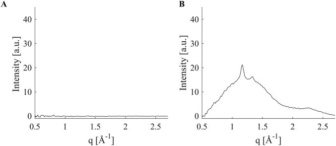
Effect of two-parameter background subtraction on PLLA intensity. Comparison of (A) the residual of a representative two-parameter subtraction of one background dataset from another and (B) the signal due to PLLA (from two 30-s acquisitions) isolated using two-parameter background subtraction.
Polarized Light Microscopy of Crimped and Deployed Scaffold Sections.
Polarized light micrographs were acquired at 4×, 10×, or 32× magnification through crossed linear polarizers using a Zeiss Universal microscope equipped with a Canon EOS DS30 camera. Image composites at 32× magnification were stitched together using Adobe Photoshop, Illustrator, and Microsoft Powerpoint. Dotted white lines have been used to indicate the position where two different images have been stitched together.
Estimating the Strain Imposed on a U Crest During Crimping
The strain field imposed during crimping can be visualized by considering lines of material points on the outer diameter surface that are equally spaced along z, and on the outer bend surface that are equally spaced along r on an as-cut U crest before deformation (Fig. S1A, Left). Crimping places the inner bend (IB) of the U crest under compression and the outer bend (OB) under tension. The compressive forces create a bulge at the IB, distorting the spacing of material points in the θ–z plane and along the r direction (Fig. S1A, Right).
Neglecting any changes due to crystallization (the density difference between the crystalline and amorphous phases is less than 3%) (42), incompressibility can be applied to estimate the dimensions of the volume element in the crimped state (Fig. S1B, Right). That is, the tensile forces at the OB cause material points to move apart in the θ direction (Fig. S1A, Right) with a concomitant decrease in the spacing of points on the OB surface along the r direction (Fig. S1A, Right). The magnitude of the strain in the r direction can be estimated from SEM images that show crimping increases the thickness at the IB to 180 μm (∼20% elongation in the r direction relative to the uniform 150-μm thickness of the as-cut scaffold) and decreases the thickness at the OB to 100 μm (∼33% compression in the r direction relative to the initial 150-μm thickness). The tensile stresses along the θ direction during crimping tend to elongate the material in the θ direction; this elongation is in the range from ∼50% (if there is no strain in the z direction, as illustrated in Fig. S1 A and B, Right) to 100% (if the strain in z equals that observed in the r direction). It is this elongation in the θ direction that drives the orientation of PLLA chains near the OB of a U crest, evident in polarized light micrographs and diffraction patterns (Fig. S5F).
Mechanical Characterization of Poly (l-lactide) Vascular Scaffolds
To explore a range of hoop elongations and axial elongations, pure PLLA was extruded into preforms with their dimensions selected to give identical final diameter and thickness when blow-molded to an expanded tube (3.5 mm OD, 150 µm thickness). The hoop elongation was varied mainly by the choice of the preform radius, and the axial elongation was varied by the axial displacement imposed during blow-molding/tube expansion (Table S1 and Fig. S2). The expanded tubes were then laser-cut either into specimens for tensile measurements (both for hoop direction and for axial direction) or into scaffolds that were crimped and deployed in identical conditions to examine the effect of processing history on scaffold performance (43).
Deformation in Metal Stents Compared with PLLA Scaffolds
Metals and polymers are subjected to tube-forming and laser-cutting to create as-cut stents and scaffolds, which can be crimped for deployment in coronary arteries. Despite the similarities in processing, the resulting morphology of deployed metal stents and PLLA scaffolds is dramatically different. As-cut metal stents are obtained by laser-cutting a pattern of struts onto tubes of the respective metal alloy (e.g., Co–Cr, stainless steel, and Mg). It is possible to directly obtain as-cut PLLA scaffolds from extruded tubes, but it is not desirable. Extruded PLLA tubes are mostly amorphous and have polymer chains aligned along the z direction, which results in poor hoop strength. As a result, PLLA preforms made from extruded tubes are first expanded to the arterial dimensions and then laser-cut. The process of tube expansion results in oriented crystallization and preferential alignment of PLLA chains along the circumference, which enhances hoop strength in the PLLA scaffold.
The as-cut stents and scaffolds are subsequently crimped, which places the inner bends of U crests under compression and the outer bends under tension. At first, it appears that crimping should weaken the material, which is true for metal stents but not for PLLA scaffolds. Reports in the literature indicate reduced mechanical properties for crimped metal stents in comparison with uncrimped metal stents (44). In PLLA scaffolds, the material at the inner bend plastically deforms and protrudes along the r direction to form bulges, which have no counterpart in metal stents (Fig. S3 A and B, i). Near the outer bend, elongation of material augments chain orientation (Fig. 3), which enhances tensile strength of the PLLA scaffold. The formation of diamond-shaped voids upon deployment is closely associated with the semicrystalline morphology and orientation of chains in polymers; diamond-shaped voids are not observed in metal stents (Fig. S3 A and B, iii). Unlike metal stents, the multiplicity of morphologies in crimped PLLA scaffolds plays a central role in increasing scaffold strength and enabling deployment without fracture.
Aligning and Mounting 15-µm-Thick Microtomed Sections for Microdiffraction Experiments
To perform linear scans along selected lines across a sample (here from the inner bend to the outer bend of a U crest; Fig. S4A), it is necessary to properly orient the sample with respect to the translation apparatus at the beamline. Embedding medium around a microtomed sample stabilizes its shape (e.g., preventing the sample from rolling into a scroll) and facilitates holding the sample in place. However, when the sample was mounted on the beamline (APS beamline 2-ID-D), only an X-ray camera was available, which cannot discriminate between the embedding medium and the scaffold, which have similar electron density. Therefore, we mount the sections in a specific orientation and position in a frame that can be quickly and properly oriented and positioned in the beam. Specifically, thin sections of the embedded scaffold (in the crimped and deployed state) were placed between two 1-µm-thick silicon nitride membranes supported on silicon frames (window size 2.0 mm × 2.0 mm, Norcada NX5200F). To facilitate alignment of samples for microdiffration line scans along the z direction and θ direction, the specimens were oriented such that the z and θ axes were parallel to edges of the silicon frame (Fig. S4B). Inspection using polarized light showed that the sections did not move during transport. The boundary between the silicon frame and the silicon nitride membrane was readily identified using the X-ray camera (e.g., Fig. S4B, white + marks). The positions of selected points on the specimen relative to the frame (measured using a polarized light microscope) were used to specify the coordinates of points at which to begin and end a line scan of X-ray microdiffraction measurements (e.g., Fig. S4B, black + marks on the inner and outer bend of the U crest of section C45 described in Fig. 3).
X-ray beam damage is always a concern with polymers, particularly when the specimen is only 15 µm thick. Therefore, we acquired pairs of wide-angle X-ray scattering patterns using two sequential 30-s exposures. The difference between the two scattering patterns was used to quantify the extent of beam damage. Relative to the first of the two acquisitions, the second acquisition showed a reduction of intensity of ∼20% at the (110/200) diffraction. This difference was sufficiently small that we chose to use sum of the two acquisitions to maximize signal-to-noise ratio in the scattering pattern analyzed for each measurement point. The second X-ray exposure was also used to produce a slight, yet visible burn mark that provided a record of the exact position where the scattering pattern was measured.
Extreme Structural Anisotropy in a Crimped U Crest
Diffraction patterns were acquired in 5-µm steps from the IB to the OB of a crimped U crest (C45; Fig. S5A). Near the IB (Fig. S5 B–D), a broad azimuthal distribution (Fig. S5G) of (110)/(200) diffraction peaks indicates PLLA chains tilting out of plane (along the r direction). Toward the OB (Fig. S5 E and F), a steady and sharp decrease in the azimuthal width of (110)/(200) diffraction peaks confirms a highly oriented structure (along the θ direction). The crimped state displays dramatic variations in morphology on the micrometer scale.
Structural Homogeneity in a Deployed U Crest
The highly anisotropic crimped microstructure is transformed during deployment. Diffraction patterns from the IB to the OB (acquired in 5-µm intervals) of section D40 (Fig. S6A) are extremely similar (Fig. S6 B–D), suggesting a highly uniform structure. The narrow azimuthal width (∼10°) (Fig. S6E) of the (110)/(200) diffraction peaks indicates a high degree of orientation (along the θ direction) in the deployed scaffold.
X-Ray Microdiffraction Data Analysis
Microdiffraction experiments were performed using 15-μm-thick sections of the polymer PLLA (beamline 2-ID-D, 200-nm spot size, APS, Argonne National Laboratory). Due to the small thickness of the sample, the scattering intensity from the PLLA sections is a mere 6% above the background (Fig. S7). Over the course of the 72 h of microdiffraction beamtime, the background varied in excess of 10% (Fig. S8), making it difficult to isolate the scattering due to the thin PLLA section.
Fig. S8.
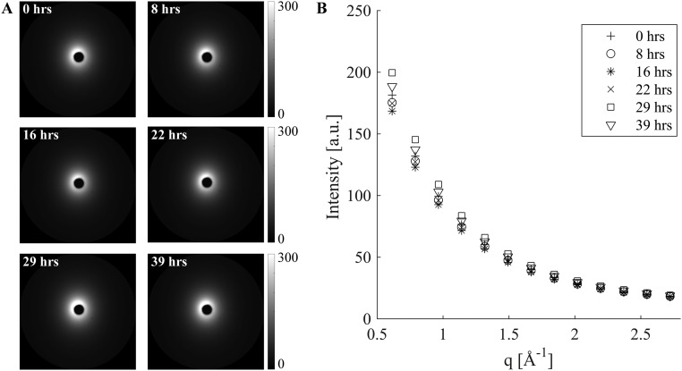
Variation in background scattering. Representative background scattering patterns acquired over a period of 39 h presented as (A) 2D images and (B) azimuthally averaged I(q) plots.
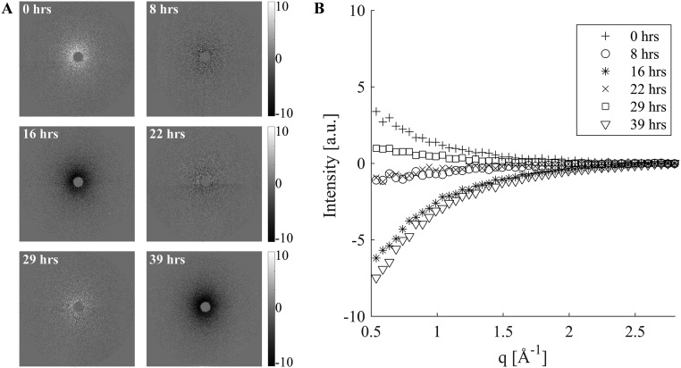
To properly account for variations in background intensity, we studied 20 background patterns measured with the same acquisition time that was used for the samples (30 s), at intervals of between 1 min and 8 h over the course of 40 h of beamtime. The 20 background patterns do not superimpose, and the variations at low q (0.5 < q < 0.55 Å−1) are much greater (∼17%) than the variations (∼8.5%) at high q (2.7 < q < 2.8 Å−1) (Fig. S8). Thus, the background changes in shape as well as intensity. The beam intensity was recorded with every acquisition. The average intensity at high q (2.7 < q < 2.8 Å−1) approximately tracks the beam intensity, but not exactly. Therefore, the conventional method of background subtraction (normalizing by the beam intensity recorded with each acquisition) is not appropriate. The presence of a high-q interval (2.7 < q < 2.8 Å−1) in which the PLLA contribution is negligible offers the option of using the average intensity at high-q as an internal standard for the beam intensity (Fig. S9). The remaining variations of the background at low q are, however, comparable to the total number of counts due to a 15-μm-thick PLLA section (the scale used in Fig. S9B corresponds to the maximum signal contributed by a 15-μm PLLA section in a single 30-s acquisition).
Fig. S9.
Deviation among background patterns at low q, despite using an internal standard for beam intensity presented as (A) 2D images and (B) azimuthally averaged I(q). Background patterns (Fig. S8) were analyzed in two groups (1–14 before the synchrotron beam going down and 15–20 afterward). The average of the patterns in a group was used as the background for that group. Normalization by the intensity in the q range 2.7–2.8 Å−1 before subtraction produced a near-zero residual only for q > 2.4 Å−1; at low q, the residual varied from +2% to −4% of the overall background. Relative to the maximum signal contributed by a single 30-s acquisition of a 15-μm PLLA section (its 110/200 peak), the low-q residual ranges from −40% to +25%, swamping out the variations among the PLLA patterns.
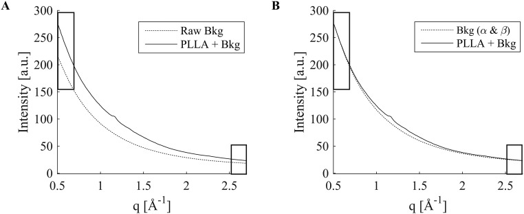
The background residuals have a very consistent shape (Fig. S9) that matches the shape of the background patterns as a whole (Fig. S8), consistent with the hypothesis that the additional effect (beyond the effect of beam intensity) is likely due to small variations in the air, e.g., pressure or humidity. In turn, this suggests a two-parameter background subtraction method. We take advantage of the fact that the scattering due to background plus PLLA is indistinguishable from the background at both the low-q and high-q limits of the experimentally accessible q range (black rectangles in Fig. S7). Therefore, each scattering pattern contains sufficient information to compute two parameters that capture the ∼17% variations in the magnitude of the air scattering (the difference between the low-q and high-q intensity, ΔI) and the small variations in the high-q intensity, Ih. We test a simple two-parameter background subtraction method in which the background pattern is scaled to accord with the sample’s ΔI, and then a small offset is applied to match the sample’s Ih. If the scattered intensity for background plus sample is denoted S(q,Φ) and that of the background is B(q,Φ), then
| [S1] |
where α = ΔIS/ΔIB and β = Ih,S − αIh,B with the subscript denoting the pattern i = S or B for which the quantity ΔIi or Ih,i is evaluated. The method is applied to 2D datasets; for illustration, the azimuthally averaged plots, I(q), are shown for a pair of S(q,Φ) and B(q,Φ) in Fig. S10A and for S(q,Φ) and αB(q,Φ) + β in Fig. S10B. To test the ability of this method to precisely null-out variations in the background, we used the two groups of background patterns described above (Figs. S8 and S9), patterns 1–14 before the synchrotron beam going down and 15–20 afterward. The average of the patterns in a group was used as the B(q,Φ) for that group. For a particular background pattern, S(q,Φ) intensities at low q (0.5 < q < 0.55 Å−1) and high q (2.7 < q < 2.8 Å−1) were evaluated for each pattern, and pixel by pixel, αB(q,Φ) + β was subtracted from S(q,Φ). The residuals are shown in Fig. S11 using the same scale as Fig. S9, for which the maximum signal contributed by a single 30-s acquisition of a PLLA thin section is 10. The residual is consistently less than ±1 (Fig. S12), i.e., less than 5% of the PLLA signal (residual <0.5% of background).
Fig. S10.
Schematic illustration of two-parameter background subtraction. (A) When the average of background patterns (Raw Bkg) is subtracted from the sample diffraction pattern (PLLA + Bkg), large disparities at q values at which sample plus background is known to be indistinguishable from the background [marked by rectangles (compare Fig. S7)] are observed. This disparity cannot be removed with simple scaling (Fig. S9). (B) The disparity can be removed by a two-parameter adjustment αB(q, Φ) + β of the background [Bkg(α & β)] (see Eq. S1 and text for formulae for α and β).
Fig. S11.
Validation of two-parameter background subtraction, for the same sets of background scattering patterns as in Fig. S8 and again using the average of the patterns in a group as the background B(q, Φ) for that group. The residuals after subtraction of αB(q, Φ) + β (see text for formulae for α and β) from representative individual background patterns are shown (A) as 2D images and (B) as azimuthally averaged I(q).
Acknowledgments
This research used resources of the Advanced Photon Source (APS), a US Department of Energy (DOE) Office of Science User Facility operated for the DOE Office of Science by Argonne National Laboratory under Contract DE-AC02-06CH11357. We thank Dr. Zhonghou Cai at APS for his assistance in collecting x-ray microdiffraction data, and Mr. Troy P. Carter (Abbott Vascular) for sectioning the scaffolds. We appreciate the assistance of Dr. Nobumichi Tamura at the Advanced Light Source, Lawrence Berkeley National Laboratories, for proof-of-concept x-ray microdiffraction measurements. The Advanced Light Source is supported by the Director, Office of Science, Office of Basic Energy Sciences, of the US Department of Energy under Contract DE-AC02-05CH1123. Funding for this research was provided by Abbot Vascular.
Footnotes
Conflict of interest statement: M.B.K. and J.P.O. are employees of Abbott Vascular. Funding for this research was provided by Abbott Vascular.
This article is a PNAS Direct Submission.
This article contains supporting information online at www.pnas.org/lookup/suppl/doi:10.1073/pnas.1602311113/-/DCSupplemental.
References
- 1.Nichols M, Townsend N, Scarborough P, Rayner M. Cardiovascular disease in Europe 2014: Epidemiological update. Eur Heart J. 2014;35(42):2950–2959. doi: 10.1093/eurheartj/ehu299. [DOI] [PubMed] [Google Scholar]
- 2.Epstein AJ, Polsky D, Yang F, Yang L, Groeneveld PW. Coronary revascularization trends in the United States, 2001-2008. JAMA. 2011;305(17):1769–1776. doi: 10.1001/jama.2011.551. [DOI] [PMC free article] [PubMed] [Google Scholar]
- 3.Ormiston JA, et al. A bioabsorbable everolimus-eluting coronary stent system for patients with single de-novo coronary artery lesions (ABSORB): A prospective open-label trial. Lancet. 2008;371(9616):899–907. doi: 10.1016/S0140-6736(08)60415-8. [DOI] [PubMed] [Google Scholar]
- 4.Wiebe J, Nef HM, Hamm CW. Current status of bioresorbable scaffolds in the treatment of coronary artery disease. J Am Coll Cardiol. 2014;64(23):2541–2551. doi: 10.1016/j.jacc.2014.09.041. [DOI] [PubMed] [Google Scholar]
- 5.Stettler C, et al. Outcomes associated with drug-eluting and bare-metal stents: A collaborative network meta-analysis. Lancet. 2007;370(9591):937–948. doi: 10.1016/S0140-6736(07)61444-5. [DOI] [PubMed] [Google Scholar]
- 6.Ong DS, Jang I-K. Causes, assessment, and treatment of stent thrombosis–intravascular imaging insights. Nat Rev Cardiol. 2015;12(6):325–336. doi: 10.1038/nrcardio.2015.32. [DOI] [PubMed] [Google Scholar]
- 7.Onuma Y, Serruys PW. Bioresorbable scaffold: The advent of a new era in percutaneous coronary and peripheral revascularization? Circulation. 2011;123(7):779–797. doi: 10.1161/CIRCULATIONAHA.110.971606. [DOI] [PubMed] [Google Scholar]
- 8.Oberhauser JP, Hossainy S, Rapoza RJ. Design principles and performance of bioresorbable polymeric vascular scaffolds. EuroIntervention. 2009;5(Suppl F):F15–F22. doi: 10.4244/EIJV5IFA3. [DOI] [PubMed] [Google Scholar]
- 9.Derby B. Printing and prototyping of tissues and scaffolds. Science. 2012;338(6109):921–926. doi: 10.1126/science.1226340. [DOI] [PubMed] [Google Scholar]
- 10.Tibbitt MW, Rodell CB, Burdick JA, Anseth KS. Progress in material design for biomedical applications. Proc Natl Acad Sci USA. 2015;112(47):14444–14451. doi: 10.1073/pnas.1516247112. [DOI] [PMC free article] [PubMed] [Google Scholar]
- 11.Langer R, Tirrell DA. Designing materials for biology and medicine. Nature. 2004;428(6982):487–492. doi: 10.1038/nature02388. [DOI] [PubMed] [Google Scholar]
- 12.Agrawal CM, Haas KF, Leopold DA, Clark HG. Evaluation of poly(L-lactic acid) as a material for intravascular polymeric stents. Biomaterials. 1992;13(3):176–182. doi: 10.1016/0142-9612(92)90068-y. [DOI] [PubMed] [Google Scholar]
- 13.Burdick JA, Frankel D, Dernell WS, Anseth KS. An initial investigation of photocurable three-dimensional lactic acid based scaffolds in a critical-sized cranial defect. Biomaterials. 2003;24(9):1613–1620. doi: 10.1016/s0142-9612(02)00538-0. [DOI] [PubMed] [Google Scholar]
- 14.Kang S-K, et al. Bioresorbable silicon electronic sensors for the brain. Nature. 2016;530(7588):71–76. doi: 10.1038/nature16492. [DOI] [PubMed] [Google Scholar]
- 15.Rolland JP, et al. Direct fabrication and harvesting of monodisperse, shape-specific nanobiomaterials. J Am Chem Soc. 2005;127(28):10096–10100. doi: 10.1021/ja051977c. [DOI] [PubMed] [Google Scholar]
- 16.Farokhzad OC, et al. Targeted nanoparticle-aptamer bioconjugates for cancer chemotherapy in vivo. Proc Natl Acad Sci USA. 2006;103(16):6315–6320. doi: 10.1073/pnas.0601755103. [DOI] [PMC free article] [PubMed] [Google Scholar]
- 17.Ormiston JA, et al. First serial assessment at 6 months and 2 years of the second generation of absorb everolimus-eluting bioresorbable vascular scaffold: A multi-imaging modality study. Circ Cardiovasc Interv. 2012;5(5):620–632. doi: 10.1161/CIRCINTERVENTIONS.112.971549. [DOI] [PubMed] [Google Scholar]
- 18.Sarno G, et al. Morphological and functional evaluation of the bioresorption of the bioresorbable everolimus-eluting vascular scaffold using IVUS, echogenicity and vasomotion testing at two year follow-up: A patient level insight into the ABSORB A clinical trial. Int J Cardiovasc Imaging. 2012;28(1):51–58. doi: 10.1007/s10554-010-9769-y. [DOI] [PubMed] [Google Scholar]
- 19.Serruys PW, et al. A polylactide bioresorbable scaffold eluting everolimus for treatment of coronary stenosis: 5-year follow-up. J Am Coll Cardiol. 2016;67(7):766–776. doi: 10.1016/j.jacc.2015.11.060. [DOI] [PubMed] [Google Scholar]
- 20.Grijpma DW, Pennings AJ. (Co) polymers of L-lactide, 2. Mechanical properties. Macromol Chem Phys. 1994;195(5):1649–1663. [Google Scholar]
- 21.Xu H, et al. Formation of shish-kebabs in injection-molded poly(L-lactic acid) by application of an intense flow field. ACS Appl Mater Interfaces. 2012;4(12):6774–6784. doi: 10.1021/am3019756. [DOI] [PubMed] [Google Scholar]
- 22.Nakafuku C, Takehisa SY. Glass transition and mechanical properties of PLLA and PDLLA-PGA copolymer blends. J Appl Polym Sci. 2004;93(5):2164–2173. [Google Scholar]
- 23.Renouf-Glauser AC, Rose J, Farrar DF, Cameron RE. The effect of crystallinity on the deformation mechanism and bulk mechanical properties of PLLA. Biomaterials. 2005;26(29):5771–5782. doi: 10.1016/j.biomaterials.2005.03.002. [DOI] [PubMed] [Google Scholar]
- 24.Hu Y, Rogunova M, Topolkaraev V, Hiltner A, Baer E. Aging of poly(lactide)/poly(ethylene glycol) blends. Part 1. Poly(lactide) with low stereoregularity. Polymer (Guildf) 2003;44(19):5701–5710. [Google Scholar]
- 25.Broz ME, VanderHart DL, Washburn NR. Structure and mechanical properties of poly(D,L-lactic acid)/poly(ε -caprolactone) blends. Biomaterials. 2003;24(23):4181–4190. doi: 10.1016/s0142-9612(03)00314-4. [DOI] [PubMed] [Google Scholar]
- 26.Rathi S, et al. Toughening semicrystalline poly(lactic acid) by morphology alteration. Polymer (Guildf) 2011;52(19):4184–4188. [Google Scholar]
- 27.Grijpma DW, Pennings AJ. (Co) polymers of L-lactide, 1. Synthesis, thermal properties and hydrolytic degradation. Macromol Chem Phys. 1994;195(5):1633–1647. [Google Scholar]
- 28.Huang MH, Li S, Vert M. Synthesis and degradation of PLA-PCL-PLA triblock copolymer prepared by successive polymerization of ε-caprolactone and DL-lactide. Polymer (Guildf) 2004;45(26):8675–8681. [Google Scholar]
- 29.Li S. Hydrolytic degradation characteristics of aliphatic polyesters derived from lactic and glycolic acids. J Biomed Mater Res. 1999;48(3):342–353. doi: 10.1002/(sici)1097-4636(1999)48:3<342::aid-jbm20>3.0.co;2-7. [DOI] [PubMed] [Google Scholar]
- 30.Rizik DG, Padaliya BB. Early U.S. experience following FDA approval of the ABBOTT vascular bioresorbable vascular scaffold: Optimal deployment technique using high resolution coronary artery imaging. J Interv Cardiol. 2016 doi: 10.1111/joic.12329. [DOI] [PubMed] [Google Scholar]
- 31.Pache J, et al. Intracoronary stenting and angiographic results: Strut thickness effect on restenosis outcome (ISAR-STEREO-2) trial. J Am Coll Cardiol. 2003;41(8):1283–1288. doi: 10.1016/s0735-1097(03)00119-0. [DOI] [PubMed] [Google Scholar]
- 32.Bergström JS, Hayman D. An overview of mechanical properties and material modeling of polylactide (PLA) for medical applications. Ann Biomed Eng. 2016;44(2):330–340. doi: 10.1007/s10439-015-1455-8. [DOI] [PubMed] [Google Scholar]
- 33.Ice GE, Budai JD, Pang JWL. The race to x-ray microbeam and nanobeam science. Science. 2011;334(6060):1234–1239. doi: 10.1126/science.1202366. [DOI] [PubMed] [Google Scholar]
- 34.Radu MD, Onuma Y, Rapoza RJ, Diletti R, Serruys PW. In vivo visualisation by three-dimensional optical coherence tomography of stress crazing of a bioresorbable vascular scaffold implanted for treatment of human coronary stenosis. EuroIntervention. 2012;7(12):1461–1463. doi: 10.4244/EIJV7I12A227. [DOI] [PubMed] [Google Scholar]
- 35.Martin C, et al. Investigation of the variation in orientation and crystallinity in poly(ethylene terephthalate) containers using microfocus X-ray diffraction. J Synchrotron Radiat. 1997;4(Pt 4):223–227. doi: 10.1107/S0909049597004512. [DOI] [PubMed] [Google Scholar]
- 36.Donald AM, Kramer EJ. The competition between shear deformation and crazing in glassy polymers. J Mater Sci. 1982;17(7):1871–1879. [Google Scholar]
- 37.Iqbal J, et al. Bioresorbable scaffolds: Rationale, current status, challenges, and future. Eur Heart J. 2014;35(12):765–776. doi: 10.1093/eurheartj/eht542. [DOI] [PubMed] [Google Scholar]
- 38.Kossuth MB, Perkins LEL, Rapoza RJ. Design principles of bioresorbable polymeric scaffolds. Interv Cardiol Clin. 2016;5(3):349–355. doi: 10.1016/j.iccl.2016.02.004. [DOI] [PubMed] [Google Scholar]
- 39.Schmitz KP, et al. 2009. Polymeric, degradable drug-eluting stents and coatings. US Patent Appl 13/057,974.
- 40.Wang Y. 2014. Bioabsorbable scaffolds made from composites. US Patent Appl 13/107,643.
- 41.Cai Z, et al. Performance of a high-resolution x-ray microprobe at the Advanced Photon Source. AIP Conf Proc. 2000;521(30):31–34. [Google Scholar]
- 42.Aou K, Kang S, Hsu SL. Morphological study on thermal shrinkage and dimensional stability associated with oriented poly (lactic acid) Macromolecules. 2005;38(18):7730–7735. [Google Scholar]
- 43.Glauser T, et al. 2015. Controlling crystalline morphology of a bioabsorbable stent. US Patent Appl 12/559,400.
- 44.Galvin E. 2014. Characterisation of the performance of an absorbable magnesium stent by experimental and numerical analysis. PhD thesis (Dublin City University, Dublin, Ireland)
- 45.Basalus MW, et al. Recent insights from scanning electron microscopic assessment of durable polymer-coated drug-eluting stents. Interv Cardiol. 2012;4(6):661–674. [Google Scholar]
- 46.Ding N, Pacetti S, Tang F, Gada M, Roorda W. XIENCE V (TM) stent design and rationale. J Interv Cardiol. 2009;22(s1):S18–S27. [Google Scholar]


